Über den Beitrag
Dieses ist nun die Fortsetzung zum ersten Teil meines Beitrages über den 9-Achsensensor MPU9250 (und den MPU6500). Im letzten Teil bin ich auf die technischen Eigenschaften eingegangen und hatte angefangen, meine Bibliothek MPU9250_WE vorzustellen. Diese könnt ihr direkt von GitHub herunterladen oder über den Bibliotheksmanager der Arduino IDE installieren.
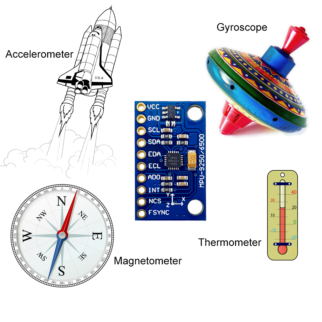
Ich hatte gezeigt, wie ihr die Daten des Beschleunigungssensors, des Gyroskops, des Magnetometers und des Thermometers abruft und wie die Kalibrierung funktioniert.
In diesem Teil geht es um die folgenden Themen:
- Erfassung von Winkeln
- Interrupts
- Low-Power / Cycle Modus
- FIFO Puffer
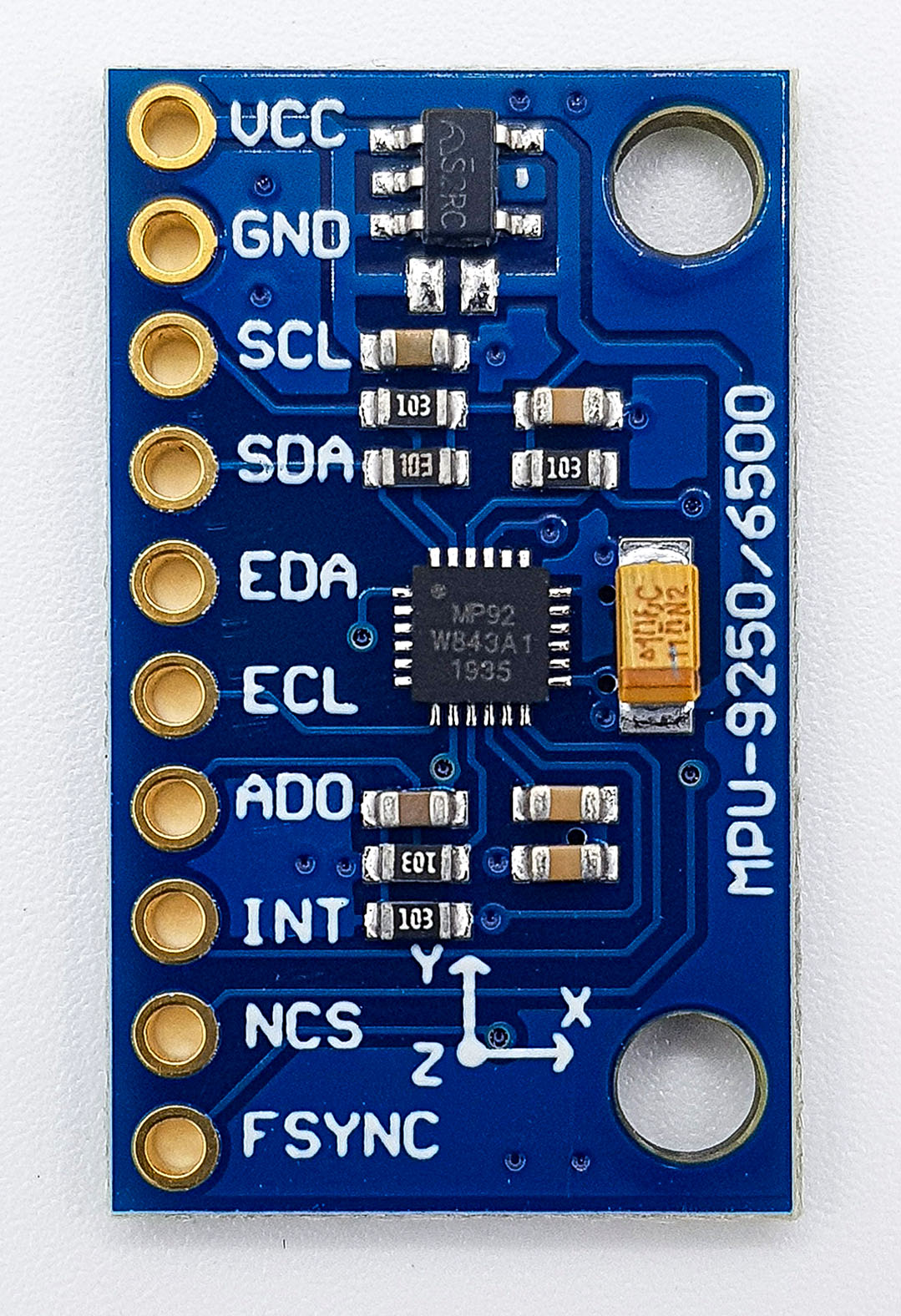
Der MPU9250 am Arduino
Die unten abgebildete Schaltung habe ich für die Beispielsketche verwendet:

Einführung in die Bibliothek MPU9250_WE – Teil 2
Winkel
Ihr könnt die (Erd-)beschleunigungsdaten nutzen, um Neigungswinkel zu berechnen. Dabei müsst ihr sicherstellen, dass keine zusätzliche Beschleunigung auf den MPU9250 wirkt. Ich habe dazu zwei Methoden implementiert.
Beispielsketch 6: MPU9250_angles_and_orientation
In diesem Sketch berechne ich die Winkel zwischen den Achsen und der Horizontalen ganz schlicht aus dem Arcussinus des Beschleunigungswertes.
![\[ \alpha=\arcsin(\text{g-Wert}) \]](https://wolles-elektronikkiste.de/wp-content/ql-cache/quicklatex.com-6b311958c2e16f27b4e6bfe4fe554d48_l3.png "Rendered by QuickLaTeX.com")
Für kleine Winkel funktioniert das einwandfrei, bei größeren Winkeln nimmt der Fehler zu. Warum das so ist, habe ich in meinem Beitrag über den MMA7361 erklärt. Bis 60° war die Abweichung bei meinen Versuchen kleiner als ein Grad.
Für diesen Sketch empfehle ich die autoOffset() Methode. Mithilfe dieser Funktion startet ihr mit einem Winkel von 0° für die x- und y-Achse. Für die z-Achse erhaltet ihr einen Startwert von 90°. Für die Neigungswinkel erhaltet ihr aber nur dann vernünftige Werte, wenn ihr den MPU9250 für die Kalibrierung flach positioniert.
Hier aber zunächst der Sketch.
#include <MPU9250_WE.h>
#include <Wire.h>
#define MPU9250_ADDR 0x68

/* There are several ways to create your MPU9250 object:
 * MPU9250_WE myMPU9250 = MPU9250_WE()              -> uses Wire / I2C Address = 0x68
 * MPU9250_WE myMPU9250 = MPU9250_WE(MPU9250_ADDR)  -> uses Wire / MPU9250_ADDR
 * MPU9250_WE myMPU9250 = MPU9250_WE(&wire2)        -> uses the TwoWire object wire2 / MPU9250_ADDR
 * MPU9250_WE myMPU9250 = MPU9250_WE(&wire2, MPU9250_ADDR) -> all together
 * Successfully tested with two I2C busses on an ESP32
 */
MPU9250_WE myMPU9250 = MPU9250_WE(MPU9250_ADDR);

void setup() {
  Serial.begin(115200);
  Wire.begin();
  if(!myMPU9250.init()){
    Serial.println("MPU9250 does not respond");
  }
  else{
    Serial.println("MPU9250 is connected");
  }

  /* The slope of the curve of acceleration vs measured values fits quite well to the theoretical
   * values, e.g. 16384 units/g in the +/- 2g range. But the starting point, if you position the
   * MPU9250 flat, is not necessarily 0g/0g/1g for x/y/z. The autoOffset function measures offset
   * values. It assumes your MPU9250 is positioned flat with its x,y-plane. The more you deviate
   * from this, the less accurate will be your results.
   * The function also measures the offset of the gyroscope data. The gyroscope offset does not
   * depend on the positioning.
   * This function needs to be called at the beginning since it can overwrite your settings!
   */
  Serial.println("Position you MPU9250 flat and don't move it - calibrating...");
  delay(1000);
  myMPU9250.autoOffsets();
  Serial.println("Done!");

  /*  This is a more accurate method for calibration. You have to determine the minimum and maximum
   *  raw acceleration values of the axes determined in the range +/- 2 g.
   *  You call the function as follows: setAccOffsets(xMin,xMax,yMin,yMax,zMin,zMax);
   *  Use either autoOffset or setAccOffsets, not both.
   */
  //myMPU9250.setAccOffsets(-14240.0, 18220.0, -17280.0, 15590.0, -20930.0, 12080.0);

  /*  Sample rate divider divides the output rate of the gyroscope and accelerometer.
   *  Sample rate = Internal sample rate / (1 + divider)
   *  It can only be applied if the corresponding DLPF is enabled and 0<DLPF<7!
   *  Divider is a number 0...255
   */
  //myMPU9250.setSampleRateDivider(5);

  /*  MPU9250_ACC_RANGE_2G      2 g
   *  MPU9250_ACC_RANGE_4G      4 g
   *  MPU9250_ACC_RANGE_8G      8 g
   *  MPU9250_ACC_RANGE_16G    16 g
   */
  myMPU9250.setAccRange(MPU9250_ACC_RANGE_2G);

  /*  Enable/disable the digital low pass filter for the accelerometer
   *  If disabled the bandwidth is 1.13 kHz, delay is 0.75 ms, output rate is 4 kHz
   */
  myMPU9250.enableAccDLPF(true);

 /*  Digital low pass filter (DLPF) for the accelerometer (if DLPF enabled)
   *  MPU9250_DPLF_0, MPU9250_DPLF_2, ...... MPU9250_DPLF_7
   *   DLPF     Bandwidth [Hz]      Delay [ms]    Output rate [kHz]
   *     0           460               1.94           1
   *     1           184               5.80           1
   *     2            92               7.80           1
   *     3            41              11.80           1
   *     4            20              19.80           1
   *     5            10              35.70           1
   *     6             5              66.96           1
   *     7           460               1.94           1
   */
  myMPU9250.setAccDLPF(MPU9250_DLPF_6);
}

void loop() {
  xyzFloat gValue = myMPU9250.getGValues();
  xyzFloat angle = myMPU9250.getAngles();

/* For g-values the corrected raws are used */
  Serial.print("g-x      = ");
  Serial.print(gValue.x);
  Serial.print("  |  g-y      = ");
  Serial.print(gValue.y);
  Serial.print("  |  g-z      = ");
  Serial.println(gValue.z);

/* Angles are also based on the corrected raws. Angles are simply calculated by
   angle = arcsin(g Value) */
  Serial.print("Angle x  = ");
  Serial.print(angle.x);
  Serial.print("  |  Angle y  = ");
  Serial.print(angle.y);
  Serial.print("  |  Angle z  = ");
  Serial.println(angle.z);

  Serial.print("Orientation of the module: ");
  Serial.println(myMPU9250.getOrientationAsString());

  Serial.println();

  delay(1000);
}
Ich habe fast alle Funktionen schon in Teil 1 des Beitrages erklärt. Hier kommen folgende Funktionen hinzu:
getAngle()liefert den Winkel der x-, y- und z-Achse gegenüber der Horizontalen in Grad zurück.- g-Werte über 1 werden auf 1 beschnitten, da die Arcussinus Funktion nicht für größere Werte definiert ist.
getOrientationAsString()gibt an, welche Achse den größten positiven Winkel hat.- Mögliche Rückgabewerte sind: x up, x down, y up, y down, z up, z down.
- Eine Alternative ist
getOrientation(). Der Rückgabewert ist ein enum (MPU9250_orientation). Zur Definition schaut in MPU9250_WE.h.
Ausgabe von MPU9250_angles_and_orientation.ino
Für die folgende Ausgabe habe ich das Modul um die y-Achse gedreht, also die x-Achse aufgerichtet.

Die Summe der Winkel von x und z müssten bei diesem Vorgang immer 90° sein. Das ist jedoch offensichtlich nicht der Fall. Wie schon erwähnt, sind die großen Winkel fehlerbehaftet.
Beispielsketch 7: MPU9250_pitch_and_roll.ino
Bei dieser Methode werden für die Berechnung der Winkel mehrere Achsen herangezogen. Dadurch sind die Werte bei großen Winkeln genauer als bei der schlichten Arcussinus Methode. Hingegen ist bei kleinen Winkeln die letztere Methode vorzuziehen. Um die Methode abzugrenzen, habe ich mich der Nomenklatur anderer Bibliotheken bedient und den Neigungswinkel der x-Achse als „pitch“ (Steigungswinkel) und den der y-Achse als „roll“ (Rollwinkel) bezeichnet. Eine Definition findet ihr beispielsweise hier.
![\[ pitch\; angle= \arctan \left(\frac{-g_x}{\sqrt{g_y^2 +g_z^2}}\right) \]](https://wolles-elektronikkiste.de/wp-content/ql-cache/quicklatex.com-28ab5ea0e3c18bcd276111618f3d857d_l3.png "Rendered by QuickLaTeX.com")
![\[ roll\;angle = \arctan\left( \frac{g_y}{g_z} \right) \]](https://wolles-elektronikkiste.de/wp-content/ql-cache/quicklatex.com-052731a415f4c76884fc53794a3d22f9_l3.png "Rendered by QuickLaTeX.com")
Zum Vergleich verwende ich in diesem Sketch beide Methoden. Probiert es aus und wählt, was euch mehr zusagt.
#include <MPU9250_WE.h>
#include <Wire.h>
#define MPU9250_ADDR 0x68

/* There are several ways to create your MPU9250 object:
 * MPU9250_WE myMPU9250 = MPU9250_WE()              -> uses Wire / I2C Address = 0x68
 * MPU9250_WE myMPU9250 = MPU9250_WE(MPU9250_ADDR)  -> uses Wire / MPU9250_ADDR
 * MPU9250_WE myMPU9250 = MPU9250_WE(&wire2)        -> uses the TwoWire object wire2 / MPU9250_ADDR
 * MPU9250_WE myMPU9250 = MPU9250_WE(&wire2, MPU9250_ADDR) -> all together
 * Successfully tested with two I2C busses on an ESP32
 */
MPU9250_WE myMPU9250 = MPU9250_WE(MPU9250_ADDR);

void setup() {
  Serial.begin(115200);
  Wire.begin();
  if(!myMPU9250.init()){
    Serial.println("MPU9250 does not respond");
  }
  else{
    Serial.println("MPU9250 is connected");
  }

  /* The slope of the curve of acceleration vs measured values fits quite well to the theoretical
   * values, e.g. 16384 units/g in the +/- 2g range. But the starting point, if you position the
   * MPU9250 flat, is not necessarily 0g/0g/1g for x/y/z. The autoOffset function measures offset
   * values. It assumes your MPU9250 is positioned flat with its x,y-plane. The more you deviate
   * from this, the less accurate will be your results.
   * The function also measures the offset of the gyroscope data. The gyroscope offset does not
   * depend on the positioning.
   * This function needs to be called at the beginning since it can overwrite your settings!
   */
  Serial.println("Position you MPU9250 flat and don't move it - calibrating...");
  delay(1000);
  myMPU9250.autoOffsets();
  Serial.println("Done!");

  /*  This is a more accurate method for calibration. You have to determine the minimum and maximum
   *  raw acceleration values of the axes determined in the range +/- 2 g.
   *  You call the function as follows: setAccOffsets(xMin,xMax,yMin,yMax,zMin,zMax);
   *  Use either autoOffset or setAccOffsets, not both.
   */
  //myMPU9250.setAccOffsets(-14240.0, 18220.0, -17280.0, 15590.0, -20930.0, 12080.0);

  /*  Sample rate divider divides the output rate of the gyroscope and accelerometer.
   *  Sample rate = Internal sample rate / (1 + divider)
   *  It can only be applied if the corresponding DLPF is enabled and 0<DLPF<7!
   *  Divider is a number 0...255
   */
  myMPU9250.setSampleRateDivider(5);

  /*  MPU9250_ACC_RANGE_2G      2 g    (default)
   *  MPU9250_ACC_RANGE_4G      4 g
   *  MPU9250_ACC_RANGE_8G      8 g
   *  MPU9250_ACC_RANGE_16G    16 g
   */
  myMPU9250.setAccRange(MPU9250_ACC_RANGE_2G);

  /*  Enable/disable the digital low pass filter for the accelerometer
   *  If disabled the bandwidth is 1.13 kHz, delay is 0.75 ms, output rate is 4 kHz
   */
  myMPU9250.enableAccDLPF(true);


  /*  Digital low pass filter (DLPF) for the accelerometer, if enabled
   *  MPU9250_DPLF_0, MPU9250_DPLF_2, ...... MPU9250_DPLF_7
   *   DLPF     Bandwidth [Hz]      Delay [ms]    Output rate [kHz]
   *     0           460               1.94           1
   *     1           184               5.80           1
   *     2            92               7.80           1
   *     3            41              11.80           1
   *     4            20              19.80           1
   *     5            10              35.70           1
   *     6             5              66.96           1
   *     7           460               1.94           1
   */
  myMPU9250.setAccDLPF(MPU9250_DLPF_6);
}

void loop() {
  xyzFloat angles = myMPU9250.getAngles();

/* This method provides quite precise values for x/y
   angles up 60°. */
  Serial.print("Angle x = ");
  Serial.print(angles.x);
  Serial.print("  |  Angle y = ");
  Serial.print(angles.y);
  Serial.print("  |  Angle z = ");
  Serial.println(angles.z);

/* Pitch and roll consider all axes for calculation. According to my experience
   it provides more reliable results at higher angles (>60°) */
  float pitch = myMPU9250.getPitch();
  float roll  = myMPU9250.getRoll();

  Serial.print("Pitch   = ");
  Serial.print(pitch);
  Serial.print("  |  Roll    = ");
  Serial.println(roll);

  Serial.println();

  delay(1000);
}
Zwei neue Funktionen werden hier verwendet:
getPitch()liefert den Pitch Winkel (x-Achse).getRoll()liefert den Roll Winkel (y-Achse).
Interrupts des MPU9250 nutzen
Der MPU9250 besitzt die folgenden Interrupts:
- Wake on Motion („WOM“): wird ausgelöst, wenn ein von euch festgelegter Beschleunigungswert überschritten wird.
- Data Ready: wird ausgelöst, wenn neue Messwerte vorliegen.
- FIFO Overflow: wird ausgelöst, wenn der FIFO Speicher voll ist (512 Bytes).
- FSYNC: ein Interrupt wird ausgelöst, wenn ein HIGH oder LOW an FSYNC anliegt (habe ich aber nicht implementiert).
Beispielsketch 8: MPU9250_wake_on_motion_interrupt.ino
Der Name „Wake on Motion“ suggeriert, dass der MPU9250 mithilfe dieses Interrupts aus dem Schlafmodus aufwachen könnte. Das ist jedoch nicht der Fall. Es handelt sich um einen schlichten Beschleunigungsinterrupt.
#include <MPU9250_WE.h>
#include <Wire.h>
#define MPU9250_ADDR 0x68

const int intPin = 2;
volatile bool motion = false;

/* There are several ways to create your MPU9250 object:
 * MPU9250_WE myMPU9250 = MPU9250_WE()              -> uses Wire / I2C Address = 0x68
 * MPU9250_WE myMPU9250 = MPU9250_WE(MPU9250_ADDR)  -> uses Wire / MPU9250_ADDR
 * MPU9250_WE myMPU9250 = MPU9250_WE(&wire2)        -> uses the TwoWire object wire2 / MPU9250_ADDR
 * MPU9250_WE myMPU9250 = MPU9250_WE(&wire2, MPU9250_ADDR) -> all together
 * Successfully tested with two I2C busses on an ESP32
 */
MPU9250_WE myMPU9250 = MPU9250_WE(MPU9250_ADDR);

void setup() {
  Serial.begin(115200);
  Wire.begin();
  if(!myMPU9250.init()){
    Serial.println("MPU9250 does not respond");
  }
  else{
    Serial.println("MPU9250 is connected");
  }

 /* The slope of the curve of acceleration vs measured values fits quite well to the theoretical
   * values, e.g. 16384 units/g in the +/- 2g range. But the starting point, if you position the
   * MPU9250 flat, is not necessarily 0g/0g/1g for x/y/z. The autoOffset function measures offset
   * values. It assumes your MPU9250 is positioned flat with its x,y-plane. The more you deviate
   * from this, the less accurate will be your results.
   * The function also measures the offset of the gyroscope data. The gyroscope offset does not
   * depend on the positioning.
   * This function needs to be called at the beginning since it can overwrite your settings!
   */
  Serial.println("Position you MPU9250 flat and don't move it - calibrating...");
  delay(1000);
  myMPU9250.autoOffsets();
  Serial.println("Done!");

  /*  This is a more accurate method for calibration. You have to determine the minimum and maximum
   *  raw acceleration values of the axes determined in the range +/- 2 g.
   *  You call the function as follows: setAccOffsets(xMin,xMax,yMin,yMax,zMin,zMax);
   *  Use either autoOffset or setAccOffsets, not both.
   */
  //myMPU9250.setAccOffsets(-14240.0, 18220.0, -17280.0, 15590.0, -20930.0, 12080.0);

  /*  Sample rate divider divides the output rate of the gyroscope and accelerometer.
   *  Sample rate = Internal sample rate / (1 + divider)
   *  It can only be applied if the corresponding DLPF is enabled and 0<DLPF<7!
   *  Divider is a number 0...255
   */
  myMPU9250.setSampleRateDivider(5);

  /*  MPU9250_ACC_RANGE_2G      2 g   (default)
   *  MPU9250_ACC_RANGE_4G      4 g
   *  MPU9250_ACC_RANGE_8G      8 g
   *  MPU9250_ACC_RANGE_16G    16 g
   */
  myMPU9250.setAccRange(MPU9250_ACC_RANGE_2G);


  /*  Enable/disable the digital low pass filter for the accelerometer
   *  If disabled the the bandwidth is 1.13 kHz, delay is 0.75 ms, output rate is 4 kHz
   */
  myMPU9250.enableAccDLPF(true);

  /*  Digital low pass filter (DLPF) for the accelerometer, if enabled
   *  MPU9250_DPLF_0, MPU9250_DPLF_2, ...... MPU9250_DPLF_7
   *   DLPF     Bandwidth [Hz]      Delay [ms]    Output rate [kHz]
   *     0           460               1.94           1
   *     1           184               5.80           1
   *     2            92               7.80           1
   *     3            41              11.80           1
   *     4            20              19.80           1
   *     5            10              35.70           1
   *     6             5              66.96           1
   *     7           460               1.94           1
   */
  myMPU9250.setAccDLPF(MPU9250_DLPF_6);

  /*  Set Accelerometer Output Data Rate in Low Power Mode
   *   MPU9250_LP_ACC_ODR_0_24      0.24 Hz
   *   MPU9250_LP_ACC_ODR_0_49      0.49 Hz
   *   MPU9250_LP_ACC_ODR_0_98      0.98 Hz
   *   MPU9250_LP_ACC_ODR_1_95      1.95 Hz
   *   MPU9250_LP_ACC_ODR_3_91      3.91 Hz
   *   MPU9250_LP_ACC_ODR_7_81      7.81 Hz
   *   MPU9250_LP_ACC_ODR_15_63    15.63 Hz
   *   MPU9250_LP_ACC_ODR_31_25    31.25 Hz
   *   MPU9250_LP_ACC_ODR_62_5     62.5 Hz
   *   MPU9250_LP_ACC_ODR_125     125 Hz
   *   MPU9250_LP_ACC_ODR_250     250 Hz
   *   MPU9250_LP_ACC_ODR_500     500 Hz
   */
  //myMPU9250.setLowPowerAccDataRate(MPU9250_LP_ACC_ODR_125);

   /*  Set the interrupt pin:
   *  MPU9250_ACT_LOW  = active-low
   *  MPU9250_ACT_HIGH = active-high (default)
   */
  myMPU9250.setIntPinPolarity(MPU9250_ACT_HIGH);

  /*  If latch is enabled the interrupt pin level is held until the interrupt status
   *  is cleared. If latch is disabled the interrupt pulse is ~50µs (default).
   */
  myMPU9250.enableIntLatch(true);

   /*  The interrupt can be cleared by any read or it will only be cleared if the interrupt
   *  status register is read (default).
   */
  myMPU9250.enableClearIntByAnyRead(false);

  /*  Enable/disable interrupts:
   *  MPU9250_DATA_READY
   *  MPU9250_FIFO_OVF
   *  MPU9250_WOM_INT
   *
   *  You can enable all interrupts.
   */
  myMPU9250.enableInterrupt(MPU9250_WOM_INT);
  //myMPU9250.disableInterrupt(MPU9250_FIFO_OVF);

  /*  Set the Wake On Motion Threshold
   *  Choose 1 (= 4 mg) ..... 255 (= 1020 mg);
   */
  myMPU9250.setWakeOnMotionThreshold(128);  // 128 = ~0.5 g

   /*  Enable/disable wake on motion (WOM) and  WOM mode:
   *  MPU9250_WOM_DISABLE
   *  MPU9250_WOM_ENABLE
   *  ***
   *  MPU9250_WOM_COMP_DISABLE   // reference is the starting value
   *  MPU9250_WOM_COMP_ENABLE    // reference is the last value
   */
  myMPU9250.enableWakeOnMotion(MPU9250_WOM_ENABLE, MPU9250_WOM_COMP_DISABLE);

  /* You can enable or disable the axes for gyroscope and/or accelerometer measurements.
   * By default all axes are enabled. Parameters are:
   * MPU9250_ENABLE_XYZ  //all axes are enabled (default)
   * MPU9250_ENABLE_XY0  // X, Y enabled, Z disabled
   * MPU9250_ENABLE_X0Z
   * MPU9250_ENABLE_X00
   * MPU9250_ENABLE_0YZ
   * MPU9250_ENABLE_0Y0
   * MPU9250_ENABLE_00Z
   * MPU9250_ENABLE_000  // all axes disabled
   */
  //myMPU9250.enableAccAxes(MPU9250_ENABLE_XYZ);
  attachInterrupt(digitalPinToInterrupt(intPin), motionISR, RISING);
  Serial.println("Turn your MPU9250 and see what happens...");

}

void loop() {
  xyzFloat gValue;

  if((millis()%1000) == 0){
    gValue = myMPU9250.getGValues();

    Serial.print(gValue.x);
    Serial.print("   ");
    Serial.print(gValue.y);
    Serial.print("   ");
    Serial.println(gValue.z);
  }
  if(motion){
    byte source = myMPU9250.readAndClearInterrupts();
    Serial.println("Interrupt!");
    if(myMPU9250.checkInterrupt(source, MPU9250_WOM_INT)){
      Serial.println("Interrupt Type: Motion");
      delay(1000);
    }
    motion = false;
    // if additional interrupts have occured in the meantime:
    myMPU9250.readAndClearInterrupts();
  }

}

void motionISR() {
  motion = true;
}
Hier gibt es eine Reihe zusätzlicher Funktionen, um die Interrupts zu steuern:
setIntPinPolarity()legt fest, ob der Interrupt Pin active-high oder active-low ist.enableLatch()steuert, ob der Interrupt als kurzes Signal am Interrupt Pin ausgegeben wird, oder ob das Signal dauerhaft auf Interrupt Level bleibt, bis der Interrupt gelöscht wird (latch = Verriegelung).- Mit
enableClearIntByAnyRead()stellt ihr ein, ob der Interrupt mit einem beliebigen Lesevorgang oder mit dem Lesen des Interrupt Statusregisters gelöscht wird. Die Funktion macht nur Sinn in Kombination mitenableLatch(). - Ihr wählt mit
enableInterrupt(), welchen Interrupt Typ ihr aktivieren wollt. Wenn ihr mehrere Interrupt Typen aktivieren möchtet, dann ruft die Funktion mehrfach auf. disableInterrupt()deaktiviert einen Interrupt.setWakeOnMotionThreshold(value)legt fest, bei welcher Beschleunigung ein Interrupt ausgelöst wird. „value“ ist die Differenz zu einem Vergleichswert und kann zwischen 1 (= 4 mg) und 255 (1.02 g) gewählt werden. Der Interrupt ist nicht achsenspezifisch. Wenn ihr bestimmte Achsen ausschließen wollt, dann müsst ihr sie deaktivieren.enableWakeOnMotion()erwartet zwei Argumente. Argument 1 schaltet den Interrupt scharf oder pausiert ihn. Mit dem zweiten Argument legt ihr den zuvor erwähnten Vergleichswert fest. Das ist entweder der Ausgangswert bei der Aktivierung des Interrupts oder der letzte Messwert.readAndClearInterrupts()liest das Interrupt Statusregister und löscht auf diesem Wege den aktiven Interrupt (wenn „latch“ aktiviert ist). Die Funktion liefert den Inhalt des Statusregisters.- Mithilfe
checkInterrupt()könnt ihr prüfen, ob ein bestimmter Interrupt ausgelöst wurde. Ihr könnt den Rückgabewert vonreadAndClearInterrupt()auch direkt auswerten. Jedoch müsst ihr dazu in MPU9250_WE.h schauen, wie dieser definiert ist.
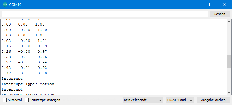
Ausgabe von MPU9250_wake_on_motion_interrupt.ino
Die folgende Ausgabe habe ich erhalten, indem ich die x-Achse des MPU9250 langsam aufgerichtet habe.
Mit diesem Sketch wurden viele Parameter und Funktionen eingeführt. Spielt am besten damit herum, um die Wirkung besser zu verstehen.
Beispielsketch 9: MPU9250_data_ready_interrupt_and_cycle.ino
Hier schlage ich zwei Fliegen mit einer Klappe. Und zwar erkläre ich den Data Ready Interrupt und den Cycle Mode zusammen in einem Sketch.
Der Cycle Modus ist ein Low-Power Modus, in dem der MPU9250 die meiste Zeit schläft und so Strom spart. In festgelegten Abständen wacht er auf, nimmt einen Beschleunigungswert und legt sich wieder hin.
Hinweis: der Cycle Modus verträgt sich nicht mit dem Tiefpassfilter (DLPF). Lasst ihn deshalb deaktiviert. Dementsprechend ist auch der Sample Rate Divider wirkungslos. Eben sowenig könnt ihr in den Wachphasen Gyroskopdaten aufnehmen (allein schon, da das Gyroskop lange 35 Millisekunden zum Aufwachen benötigt).
#include <MPU9250_WE.h>
#include <Wire.h>
#define MPU9250_ADDR 0x68

const int intPin = 2;
volatile bool dataReady = false;

/* There are several ways to create your MPU9250 object:
 * MPU9250_WE myMPU9250 = MPU9250_WE()              -> uses Wire / I2C Address = 0x68
 * MPU9250_WE myMPU9250 = MPU9250_WE(MPU9250_ADDR)  -> uses Wire / MPU9250_ADDR
 * MPU9250_WE myMPU9250 = MPU9250_WE(&wire2)        -> uses the TwoWire object wire2 / MPU9250_ADDR
 * MPU9250_WE myMPU9250 = MPU9250_WE(&wire2, MPU9250_ADDR) -> all together
 * Successfully tested with two I2C busses on an ESP32
 */
MPU9250_WE myMPU9250 = MPU9250_WE(MPU9250_ADDR);

void setup() {
  Serial.begin(115200);
  Wire.begin();
  if(!myMPU9250.init()){
    Serial.println("MPU9250 does not respond");
  }
  else{
    Serial.println("MPU9250 is connected");
  }

  /* The slope of the curve of acceleration vs measured values fits quite well to the theoretical
   * values, e.g. 16384 units/g in the +/- 2g range. But the starting point, if you position the
   * MPU9250 flat, is not necessarily 0g/0g/1g for x/y/z. The autoOffset function measures offset
   * values. It assumes your MPU9250 is positioned flat with its x,y-plane. The more you deviate
   * from this, the less accurate will be your results.
   * The function also measures the offset of the gyroscope data. The gyroscope offset does not
   * depend on the positioning.
   * This function needs to be called at the beginning since it can overwrite your settings!
   */
  Serial.println("Position you MPU9250 flat and don't move it - calibrating...");
  delay(1000);
  myMPU9250.autoOffsets();
  Serial.println("Done!");

  /*  This is a more accurate method for calibration. You have to determine the minimum and maximum
   *  raw acceleration values of the axes determined in the range +/- 2 g.
   *  You call the function as follows: setAccOffsets(xMin,xMax,yMin,yMax,zMin,zMax);
   *  Use either autoOffset or setAccOffsets, not both.
   */
  //myMPU9250.setAccOffsets(-14240.0, 18220.0, -17280.0, 15590.0, -20930.0, 12080.0);

  /*  Sample rate divider divides the output rate of the gyroscope and accelerometer.
   *  Sample rate = Internal sample rate / (1 + divider)
   *  It can only be applied if the corresponding DLPF is enabled and 0<DLPF<7!
   *  Divider is a number 0...255
   */
  myMPU9250.setSampleRateDivider(5);

  /*  MPU9250_ACC_RANGE_2G      2 g   (default)
   *  MPU9250_ACC_RANGE_4G      4 g
   *  MPU9250_ACC_RANGE_8G      8 g
   *  MPU9250_ACC_RANGE_16G    16 g
   */
  myMPU9250.setAccRange(MPU9250_ACC_RANGE_2G);

  /*  Enable/disable the digital low pass filter for the accelerometer
   *  If disabled the the bandwidth is 1.13 kHz, delay is 0.75 ms, output rate is 4 kHz
   */
  myMPU9250.enableAccDLPF(false);

  /*  Set accelerometer output data rate in low power mode (cycle enabled)
   *   MPU9250_LP_ACC_ODR_0_24          0.24 Hz
   *   MPU9250_LP_ACC_ODR_0_49          0.49 Hz
   *   MPU9250_LP_ACC_ODR_0_98          0.98 Hz
   *   MPU9250_LP_ACC_ODR_1_95          1.95 Hz
   *   MPU9250_LP_ACC_ODR_3_91          3.91 Hz
   *   MPU9250_LP_ACC_ODR_7_81          7.81 Hz
   *   MPU9250_LP_ACC_ODR_15_63        15.63 Hz
   *   MPU9250_LP_ACC_ODR_31_25        31.25 Hz
   *   MPU9250_LP_ACC_ODR_62_5         62.5 Hz
   *   MPU9250_LP_ACC_ODR_125         125 Hz
   *   MPU9250_LP_ACC_ODR_250         250 Hz
   *   MPU9250_LP_ACC_ODR_500         500 Hz
   */
  myMPU9250.setLowPowerAccDataRate(MPU9250_LP_ACC_ODR_0_24);

  /*  Set the interrupt pin:
   *  MPU9250_ACT_LOW  = active-low
   *  MPU9250_ACT_HIGH = active-high (default)
   */
  myMPU9250.setIntPinPolarity(MPU9250_ACT_HIGH);

  /*  If latch is enabled the Interrupt Pin Level is held until the Interrupt Status
   *  is cleared. If latch is disabled the Interrupt Puls is ~50µs (default).
   */
  myMPU9250.enableIntLatch(true);

  /*  The Interrupt can be cleared by any read. Otherwise the Interrupt will only be
   *  cleared if the Interrupt Status register is read (default).
   */
  myMPU9250.enableClearIntByAnyRead(false);

  /*  Enable/disable interrupts:
   *  MPU9250_DATA_READY
   *  MPU9250_FIFO_OVF
   *  MPU9250_WOM_INT
   *
   *  You can enable all interrupts.
   */
  myMPU9250.enableInterrupt(MPU9250_DATA_READY);
  //myMPU9250.disableInterrupt(MPU9250_FIFO_OVF);

  /* If cycle is set, and standby or sleep are not set, the module will cycle between
   *  sleep and taking a sample at a rate determined by setLowPowerAccDataRate().
   */
  myMPU9250.enableCycle(true);

  /* You can enable or disable the axes for gyroscope and/or accelerometer measurements.
   * By default all axes are enabled. Parameters are:
   * MPU9250_ENABLE_XYZ  //all axes are enabled (default)
   * MPU9250_ENABLE_XY0  // X, Y enabled, Z disabled
   * MPU9250_ENABLE_X0Z
   * MPU9250_ENABLE_X00
   * MPU9250_ENABLE_0YZ
   * MPU9250_ENABLE_0Y0
   * MPU9250_ENABLE_00Z
   * MPU9250_ENABLE_000  // all axes disabled
   */
  //myMPU9250.enableAccAxes(MPU9250_ENABLE_XYZ);
  attachInterrupt(digitalPinToInterrupt(intPin), dataReadyISR, RISING);

}

void loop() {
  if(dataReady){
    byte source = myMPU9250.readAndClearInterrupts();
    Serial.println("Interrupt!");
    if(myMPU9250.checkInterrupt(source, MPU9250_DATA_READY)){
      Serial.println("Interrupt Type: Data Ready");
      printData();
    }
    dataReady = false;
    myMPU9250.readAndClearInterrupts(); // if additional interrupts have occured in the meantime
  }
}

void printData(){
  xyzFloat gValue;
  gValue = myMPU9250.getGValues();

  Serial.print(gValue.x);
  Serial.print("   ");
  Serial.print(gValue.y);
  Serial.print("   ");
  Serial.println(gValue.z);
}

void dataReadyISR() {
  dataReady = true;
}
Die folgenden neuen Funktionen kommen hier zu Einsatz:
setLowPowerAccDataRate()legt die Aufwach- beziehungsweise Datenrate fest. Ihr könnt Werte zwischen 0.24 und 500 Hz einstellen.enableCycle()aktiviert oder deaktiviert den Cycle Modus.
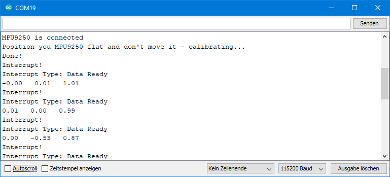
Ausgabe von MPU9250_data_ready_and_cycle.ino
Da ich die Datenrate auf 0.24 Hz eingestellt habe, wacht der MPU9250 ca. alle vier Sekunden auf und nimmt einen Messwert. Der Data Ready Interrupt steuert die Messwertaufnahme und die Ausgabe. Ihr seht, dass die Hauptschleife des Sketches kein delay enthält.
Den FIFO Speicher des MPU9250 nutzen
Der FIFO (first in, first out) Speicher ist eine Art Rekorder für Messdaten. Die Daten, die der MPU9250 zuerst hineinschreibt, liest er auch zuerst aus – daher sein Name. Der FIFO hat eine Größe von 512 Bytes. Ihr bestimmt, welche Daten in den FIFO geschrieben werden. Damit legt ihr auch fest, wie viele Datensätze in den FIFO passen. Ein Beschleunigungs- oder Gyroskopwert benötigt zwei Byte. Es werden immer die Rohdaten gespeichert. Ein x,y,z-Triple benötigt dementsprechend 6 Byte. Ich habe folgende Auswahloptionen implementiert:
- Beschleunigungswerte als vollständige Triple – 85 vollständige Triple passen (512 / 6 = 85, Rest 2) in den FIFO.
- Gyroskopwerte als vollständige Triple – 85 vollständige Triple passen.
- Beschleunigungs- und Gyroskopwerte – 42 vollständige Datensätze möglich (512 / 12 = 42, Rest 8).
Der MPU9250 kann darüber hinaus auch Gyroskopdaten einzelner Achsen, Temperaturen oder Daten externer Sensoren aufnehmen. Das habe ich allerdings nicht implementiert, sondern mich auf die o.a. Optionen beschränkt.
Zum Auslesen des FIFO Registers werden die FIFO Daten nacheinander in ein einzelnes Datenregister von einem Byte geschoben. Von dort liest man die Bytes einzeln aus und setzt sie wieder zu sinnvollen Daten zusammen. Allerdings ist den einzelnen Bytes sozusagen nicht anzusehen, ob es sich um das MSB oder LSB eines Beschleunigungs- oder Gyroskopwertes handelt. Man muss also mitzählen und in der richtigen Reihenfolge auslesen. Das lässt sich aber nur zu einem gewissen Grad automatisieren. Und um es für den User nicht zu komplex und damit fehleranfällig werden zu lassen, habe ich nicht alle Optionen implementiert.
Beispielsketch 10: MPU9250_FIFO_stop_when_full
In diesem ersten FIFO Sketch stoppt der MPU9250 die Datenaufnahme, wenn der FIFO voll ist. Das heißt, dass ihr den Startschuss gebt und die Aufnahmezeit von der Datenrate und den aufgenommenen Datentypen abhängt. Eine Kombination mit dem Cycle Modus funktioniert übrigens nicht.
Wenn der FIFO voll ist, könnt ihr euch darüber mithilfe des FIFO Overflow Interrupts informieren lassen.
Bei Aufnahme von Beschleunigungs- und Gyroskopdaten schreibt der MPU9250 immer zuerst die Beschleunigungsdaten in den FIFO. Da er in diesem Beispiel stoppt, wenn der FIFO voll ist, beginnt der FIFO mit einem Beschleunigungswert. Das ist wichtig für das korrekte Auslesen!
#include <MPU9250_WE.h>
#include <Wire.h>
#define MPU9250_ADDR 0x68

const int intPin = 2;
volatile bool fifoFull = false;

/* There are several ways to create your MPU9250 object:
 * MPU9250_WE myMPU9250 = MPU9250_WE()              -> uses Wire / I2C Address = 0x68
 * MPU9250_WE myMPU9250 = MPU9250_WE(MPU9250_ADDR)  -> uses Wire / MPU9250_ADDR
 * MPU9250_WE myMPU9250 = MPU9250_WE(&wire2)        -> uses the TwoWire object wire2 / MPU9250_ADDR
 * MPU9250_WE myMPU9250 = MPU9250_WE(&wire2, MPU9250_ADDR) -> all together
 * Successfully tested with two I2C busses on an ESP32
 */
MPU9250_WE myMPU9250 = MPU9250_WE(MPU9250_ADDR);

void setup() {
  Serial.begin(115200);
  Wire.begin();
  if(!myMPU9250.init()){
    Serial.println("MPU9250 does not respond");
  }
  else{
    Serial.println("MPU9250 is connected");
  }

  /* The slope of the curve of acceleration vs measured values fits quite well to the theoretical
   * values, e.g. 16384 units/g in the +/- 2g range. But the starting point, if you position the
   * MPU9250 flat, is not necessarily 0g/0g/1g for x/y/z. The autoOffset function measures offset
   * values. It assumes your MPU9250 is positioned flat with its x,y-plane. The more you deviate
   * from this, the less accurate will be your results.
   * The function also measures the offset of the gyroscope data. The gyroscope offset does not
   * depend on the positioning.
   * This function needs to be called at the beginning since it can overwrite your settings!
   */
  Serial.println("Position you MPU9250 flat and don't move it - calibrating...");
  delay(1000);
  myMPU9250.autoOffsets();
  Serial.println("Done!");

  /*  This is a more accurate method for calibration. You have to determine the minimum and maximum
   *  raw acceleration values of the axes determined in the range +/- 2 g.
   *  You call the function as follows: setAccOffsets(xMin,xMax,yMin,yMax,zMin,zMax);
   *  Use either autoOffset or setAccOffsets, not both.
   */
  //myMPU9250.setAccOffsets(-14240.0, 18220.0, -17280.0, 15590.0, -20930.0, 12080.0);

  /*  The gyroscope data is not zero, even if you don't move the MPU9250.
   *  To start at zero, you can apply offset values. These are the gyroscope raw values you obtain
   *  using the +/- 250 degrees/s range.
   *  Use either autoOffset or setGyrOffsets, not both.
   */
  //myMPU9250.setGyrOffsets(45.0, 145.0, -105.0);

  /*  You can enable or disable the digital low pass filter (DLPF). If you disable the DLPF, you
   *  need to select the bandwidth, which can be either 8800 or 3600 Hz. 8800 Hz has a shorter delay,
   *  but higher noise level. If DLPF is disabled, the output rate is 32 kHz.
   *  MPU9250_BW_WO_DLPF_3600
   *  MPU9250_BW_WO_DLPF_8800
   */
  myMPU9250.enableGyrDLPF();
  //myMPU9250.disableGyrDLPF(MPU9250_BW_WO_DLPF_8800); // bandwidth without DLPF

  /*  Digital Low Pass Filter for the gyroscope must be enabled to choose the level.
   *  MPU9250_DPLF_0, MPU9250_DPLF_2, ...... MPU9250_DPLF_7
   *
   *  DLPF    Bandwidth [Hz]   Delay [ms]   Output Rate [kHz]
   *    0         250            0.97             8
   *    1         184            2.9              1
   *    2          92            3.9              1
   *    3          41            5.9              1
   *    4          20            9.9              1
   *    5          10           17.85             1
   *    6           5           33.48             1
   *    7        3600            0.17             8
   *
   *    You achieve lowest noise using level 6
   */
  myMPU9250.setGyrDLPF(MPU9250_DLPF_5);

  /*  Sample rate divider divides the output rate of the gyroscope and accelerometer.
   *  Sample rate = Internal sample rate / (1 + divider)
   *  It can only be applied if the corresponding DLPF is enabled and 0<DLPF<7!
   *  Divider is a number 0...255
   */
  myMPU9250.setSampleRateDivider(99);

  /*  MPU9250_GYRO_RANGE_250       250 degrees per second (default)
   *  MPU9250_GYRO_RANGE_500       500 degrees per second
   *  MPU9250_GYRO_RANGE_1000     1000 degrees per second
   *  MPU9250_GYRO_RANGE_2000     2000 degrees per second
   */
  myMPU9250.setGyrRange(MPU9250_GYRO_RANGE_250);

  /*  MPU9250_ACC_RANGE_2G      2 g   (default)
   *  MPU9250_ACC_RANGE_4G      4 g
   *  MPU9250_ACC_RANGE_8G      8 g
   *  MPU9250_ACC_RANGE_16G    16 g
   */
  myMPU9250.setAccRange(MPU9250_ACC_RANGE_2G);

  /*  Enable/disable the digital low pass filter for the accelerometer
   *  If disabled the bandwidth is 1.13 kHz, delay is 0.75 ms, output rate is 4 kHz
   */
  myMPU9250.enableAccDLPF(true);

  /*  Digital low pass filter (DLPF) for the accelerometer, if enabled
   *  MPU9250_DPLF_0, MPU9250_DPLF_2, ...... MPU9250_DPLF_7
   *   DLPF     Bandwidth [Hz]      Delay [ms]    Output rate [kHz]
   *     0           460               1.94           1
   *     1           184               5.80           1
   *     2            92               7.80           1
   *     3            41              11.80           1
   *     4            20              19.80           1
   *     5            10              35.70           1
   *     6             5              66.96           1
   *     7           460               1.94           1
   */
  myMPU9250.setAccDLPF(MPU9250_DLPF_0);

  /*  Set the interrupt pin:
   *  MPU9250_ACT_LOW  = active-low
   *  MPU9250_ACT_HIGH = active-high (default)
   */
  //myMPU9250.setIntPinPolarity(MPU9250_ACT_LOW);

  /*  If latch is enabled the interrupt pin level is held until the interrupt status
   *  is cleared. If latch is disabled the interrupt pulse is ~50µs (default).
   */
  myMPU9250.enableIntLatch(true);

  /*  The interrupt can be cleared by any read or it will only be cleared if the interrupt
   *  status register is read (default).
   */
  //myMPU9250.enableClearIntByAnyRead(true);

  /*  Enable/disable interrupts:
   *  MPU9250_DATA_READY
   *  MPU9250_FIFO_OVF
   *  MPU9250_WOM_INT
   *
   *  You can enable all interrupts.
   */
  myMPU9250.enableInterrupt(MPU9250_FIFO_OVF);
  //myMPU9250.disableInterrupt(MPU9250_FIFO_OVF);

  /*  Set the wake on motion threshold (WOM threshold)
   *  Choose 1 (= 4 mg) ..... 255 (= 1020 mg);
   */
  //myMPU9250.setWakeOnMotionThreshold(170);

  /*  Enable/disable wake on motion (WOM) and  WOM mode:
   *  MPU9250_WOM_DISABLE
   *  MPU9250_WOM_ENABLE
   *  ***
   *  MPU9250_WOM_COMP_DISABLE   // reference is the starting value
   *  MPU9250_WOM_COMP_ENABLE    // reference is tha last value
   */
  //myMPU9250.enableWakeOnMotion(MPU9250_WOM_ENABLE, MPU9250_WOM_COMP_DISABLE);

  /* There are two different FIFO modes:
   *  MPU9250_CONTINUOUS --> samples are continuously stored in FIFO. If FIFO is full
   *  new data will replace the oldest.
   *  MPU9250_STOP_WHEN_FULL --> self-explaining
   */
  //myMPU9250.setFifoMode(MPU9250_STOP_WHEN_FULL); // used below, but explained here

  /* The argument of startFifo defines the data stored in the FIFO
   * MPU9250_FIFO_ACC --> Acceleration Data ist stored in FIFO
   * MPU9250_FIFO_GYR --> Gyroscope data is stored in FIFO
   * MPU9250_FIFO_ACC_GYR --> Acceleration and Gyroscope Data is stored in FIFO
   * The library does not (yet) support storing single gyroscope axes data, temperature
   * or data from slaves.
   */
  //myMPU9250.startFifo(MPU9250_FIFO_ACC); // used below, but explained here

  /* stopFifo():
   * - stops additional writes into Fifo
   * - clears the data type written into Fifo (acceleration and/or gyroscope
   */
  //myMPU9250.stopFifo(); // used below, but explained here

  /* sets the Fifo counter to zero */
  //myMPU9250.resetFifo(); // used below, but explained here


  /* sleep() sends the MPU9250 to sleep or wakes it up.
   * Please note that the gyroscope needs 35 milliseconds to wake up.
   */
  //myMPU9250.sleep(true);

  /* If cycle is set, and standby or sleep are not set, the module will cycle between
   * sleep and taking a sample at a rate determined by setLowPowerAccDataRate().
   */
  //myMPU9250.enableCycle(true);

  /* This is a low power standby mode for the gyro function, which allows quick enabling.
   * (see data sheet for further information)
   */
  //myMPU9250.enableGyrStandby(true);


  /* You can enable or disable the axes for gyroscope and/or accelerometer measurements.
   * By default all axes are enabled. Parameters are:
   * MPU9250_ENABLE_XYZ  //all axes are enabled (default)
   * MPU9250_ENABLE_XY0  // X, Y enabled, Z disabled
   * MPU9250_ENABLE_X0Z
   * MPU9250_ENABLE_X00
   * MPU9250_ENABLE_0YZ
   * MPU9250_ENABLE_0Y0
   * MPU9250_ENABLE_00Z
   * MPU9250_ENABLE_000  // all axes disabled
   */
  //myMPU9250.enableAccAxes(MPU9250_ENABLE_X0Z);
  //myMPU9250.enableGyrAxes(MPU9250_ENABLE_XY0);

  attachInterrupt(digitalPinToInterrupt(intPin), eventISR, RISING);
  myMPU9250.setFifoMode(MPU9250_STOP_WHEN_FULL);
  myMPU9250.enableFifo(true);
  delay(100); // in some cases a delay after enabling Fifo makes sense
}

void loop() {

  countDown();
  myMPU9250.readAndClearInterrupts();
  fifoFull = false;
  myMPU9250.startFifo(MPU9250_FIFO_ACC_GYR);

  while(!fifoFull){}
  myMPU9250.stopFifo();
  printFifo();
  myMPU9250.resetFifo();

  Serial.println("For another series of measurements, enter any key and send");

  while(!(Serial.available())){}
  Serial.read();
  Serial.println();
 }

void printFifo(){
  int count = myMPU9250.getFifoCount();
  int dataSets = myMPU9250.getNumberOfFifoDataSets();
  Serial.print("Bytes in Fifo: ");
  Serial.println(count);
  Serial.print("Data Sets: ");
  Serial.println(dataSets);

  for(int i=0; i<dataSets; i++){
    xyzFloat gValue = myMPU9250.getGValuesFromFifo();
    xyzFloat gyr = myMPU9250.getGyrValuesFromFifo();
    Serial.print("Data set ");
    Serial.print(i+1);
    Serial.println(":");

    Serial.print(gValue.x);
    Serial.print("   ");
    Serial.print(gValue.y);
    Serial.print("   ");
    Serial.println(gValue.z);

    Serial.print(gyr.x);
    Serial.print("   ");
    Serial.print(gyr.y);
    Serial.print("   ");
    Serial.println(gyr.z);
  }
}

void countDown(){
  Serial.println("Move/turn your MPU9250 to obtain interesting data");
  Serial.println();
  delay(1000);
  Serial.print("Fifo collection begins in 3, ");
  delay(1000);
  Serial.print("2, ");
  delay(1000);
  Serial.print("1, ");
  delay(1000);
  Serial.println("Now!");
}

void eventISR() {
  fifoFull = true;
}
Hier startet ein Countdown den FIFO. Ihr könnt auch andere Auslöser wählen, z.B. einen WOM Interrupt.
Ist der FIFO voll, wird das durch einen Interrupt angezeigt. Dann erfolgt das Auslesen und die Ausgabe der Daten. Danach könnt durch Senden eines Zeichens über den seriellen Monitor eine erneute FIFO Aufnahme starten.
Neue Funktionen
Folgende neue Funktionen kommen zum Einsatz:
- Mit
setFifoMode()legt ihr fest, ob ihr den kontinuierlichen oder den „stop-when-full“ Modus einsetzt. enableFifo()aktiviert oder deaktiviert ihr den FIFO.- Ihr übergebt
startFiFo()die aufzunehmenden Datentypen. Mit dieser Funktion wird aber auch der Zähler gestartet. - Mit
stopFifo()verhindert ihr, dass weitere Messwerte in den FIFO geschoben werden. Dieser Vorgang ist zwar sowieso gestoppt, wenn der FIFO voll ist, allerdings nur vorerst. Wenn ihr mit dem Auslesen beginnt, wird wieder Platz geschaffen. Und der würde ohnestopFifo()sofort mit neuen Werten gefüllt. getFifoCount()liefert euch den FIFO Zählerstand, also die Anzahl an Bytes. Wenn der FIFO voll ist, sind das 512 Bytes. Aber ihr könntet ja theoretisch auch abbrechen, bevor der FIFO voll ist.getNumberOfFifoDataSets()berechnet die Anzahl von Datensätzen im FIFO. In diesem Beispiel besteht ein Datensatz aus einem x,y,z-Tripel Beschleunigungsdaten und einem x,y,z-Tripel Gyroskopdaten, also 12 Bytes.getGValuesFromFifo()liest ein x,y,z-Tripel Beschleunigungsdaten aus und rechnet dieses in ein g-Werte Tripel um. Da der FIFO Rohdaten enthält, dürft ihr zwischen Aufnahme und Auslesen nicht die Parameter ändern (also z.B. Range oder Offsets).getGyrValuesFromFifo()liest ein x,y,z-Tripel Gyroskopdaten (Rohdaten) aus und rechnet dieses in Rotationswerte (°/s) um.resetFifo()setzt den FIFO Zähler auf null.
Ich möchte noch einmal betonen, dass ihr beim Auslesen die Reihenfolge einhalten müsst. In diesem Beispiel lest ihr Beschleunigungsdaten und Gyroskopdaten im Wechsel und beginnt mit den Beschleunigungsdaten.
Ausgabe von MPU9250_FIFO_stop_when_full.ino
Hier ein Ausschnitt der Ausgabe des Sketches. Der Sample Rate Divider war in diesem Beispiel 99. Damit nimmt der FIFO einen Datensatz in 10 Millisekunden auf. 42 Datensätze passen in den FIFO. Das bedeutet, dass eine „FIFO-Füllung“ unter diesen Bedingungen 4.2 s benötigt.

Beispielsketch 11: MPU9250_FIFO_continuous.ino
Bei dieser Methode nimmt der FIFO kontinuierlich die von euch festgelegten Datentypen auf. Hier legt ihr also nicht den Start, sondern das Ende fest. Wenn der FIFO voll ist, bevor ihr stoppt, dann schmeißt er die ältesten Daten zugunsten der neuen Daten raus.
Der MPU9250 schreibt immer vollständige Datensätze in den FIFO. Das bedeutet, ihr habt ein definiertes Ende. Der Anfang hingegen befindet sich irgendwo in einem Datensatz. Das liegt daran, der FIFO keine vollständigen Datensätze hinausschmeißt. Bei 512 Byte wird brutal gekappt. Deswegen gibt es hier eine zusätzliche Funktion, die beim Auslesen den Anfang des ersten vollständigen Datensatzes findet.
Der Beispielsketch benutzt einen WOM Interrupt als Stopp für den FIFO. Dreht den MPU9250, um den Interrupt auszulösen. Um interessante Daten zu erhalten, dreht ihn nicht zu schnell.
#include <MPU9250_WE.h>
#include <Wire.h>
#define MPU9250_ADDR 0x68

const int intPin = 2;
volatile bool womEvent = false;

/* There are several ways to create your MPU9250 object:
 * MPU9250_WE myMPU9250 = MPU9250_WE()              -> uses Wire / I2C Address = 0x68
 * MPU9250_WE myMPU9250 = MPU9250_WE(MPU9250_ADDR)  -> uses Wire / MPU9250_ADDR
 * MPU9250_WE myMPU9250 = MPU9250_WE(&wire2)        -> uses the TwoWire object wire2 / MPU9250_ADDR
 * MPU9250_WE myMPU9250 = MPU9250_WE(&wire2, MPU9250_ADDR) -> all together
 * Successfully tested with two I2C busses on an ESP32
 */
MPU9250_WE myMPU9250 = MPU9250_WE(MPU9250_ADDR);

void setup() {
  Serial.begin(115200);
  Wire.begin();
  if(!myMPU9250.init()){
    Serial.println("MPU9250 does not respond");
  }
  else{
    Serial.println("MPU9250 is connected");
  }

  /* The slope of the curve of acceleration vs measured values fits quite well to the theoretical
   * values, e.g. 16384 units/g in the +/- 2g range. But the starting point, if you position the
   * MPU9250 flat, is not necessarily 0g/0g/1g for x/y/z. The autoOffset function measures offset
   * values. It assumes your MPU9250 is positioned flat with its x,y-plane. The more you deviate
   * from this, the less accurate will be your results.
   * The function also measures the offset of the gyroscope data. The gyroscope offset does not
   * depend on the positioning.
   * This function needs to be called at the beginning since it can overwrite your settings!
   */
  Serial.println("Position you MPU9250 flat and don't move it - calibrating...");
  delay(1000);
  myMPU9250.autoOffsets();
  Serial.println("Done!");

  /*  This is a more accurate method for calibration. You have to determine the minimum and maximum
   *  raw acceleration values of the axes determined in the range +/- 2 g.
   *  You call the function as follows: setAccOffsets(xMin,xMax,yMin,yMax,zMin,zMax);
   *  Use either autoOffset or setAccOffsets, not both.
   */
  //myMPU9250.setAccOffsets(-14240.0, 18220.0, -17280.0, 15590.0, -20930.0, 12080.0);

  /*  The gyroscope data is not zero, even if you don't move the MPU9250.
   *  To start at zero, you can apply offset values. These are the gyroscope raw values you obtain
   *  using the +/- 250 degrees/s range.
   *  Use either autoOffset or setGyrOffsets, not both.
   */
  //myMPU9250.setGyrOffsets(45.0, 145.0, -105.0);

  /*  You can enable or disable the digital low pass filter (DLPF). If you disable the DLPF, you
   *  need to select the bandwidth, which can be either 8800 or 3600 Hz. 8800 Hz has a shorter delay,
   *  but higher noise level. If DLPF is disabled, the output rate is 32 kHz.
   *  MPU9250_BW_WO_DLPF_3600
   *  MPU9250_BW_WO_DLPF_8800
   */
  myMPU9250.enableGyrDLPF();
  //myMPU9250.disableGyrDLPF(MPU9250_BW_WO_DLPF_8800); // bandwidth without DLPF

  /*  Digital Low Pass Filter for the gyroscope must be enabled to choose the level.
   *  MPU9250_DPLF_0, MPU9250_DPLF_2, ...... MPU9250_DPLF_7
   *
   *  DLPF    Bandwidth [Hz]   Delay [ms]   Output Rate [kHz]
   *    0         250            0.97             8
   *    1         184            2.9              1
   *    2          92            3.9              1
   *    3          41            5.9              1
   *    4          20            9.9              1
   *    5          10           17.85             1
   *    6           5           33.48             1
   *    7        3600            0.17             8
   *
   *    You achieve lowest noise using level 6
   */
  myMPU9250.setGyrDLPF(MPU9250_DLPF_5);

  /*  Sample rate divider divides the output rate of the gyroscope and accelerometer.
   *  Sample rate = Internal sample rate / (1 + divider)
   *  It can only be applied if the corresponding DLPF is enabled and 0<DLPF<7!
   *  Divider is a number 0...255
   */
  myMPU9250.setSampleRateDivider(99);

  /*  MPU9250_GYRO_RANGE_250       250 degrees per second (default)
   *  MPU9250_GYRO_RANGE_500       500 degrees per second
   *  MPU9250_GYRO_RANGE_1000     1000 degrees per second
   *  MPU9250_GYRO_RANGE_2000     2000 degrees per second
   */
  myMPU9250.setGyrRange(MPU9250_GYRO_RANGE_250);

  /*  MPU9250_ACC_RANGE_2G      2 g   (default)
   *  MPU9250_ACC_RANGE_4G      4 g
   *  MPU9250_ACC_RANGE_8G      8 g
   *  MPU9250_ACC_RANGE_16G    16 g
   */
  myMPU9250.setAccRange(MPU9250_ACC_RANGE_2G);

  /*  Enable/disable the digital low pass filter for the accelerometer
   *  If disabled the the bandwidth is 1.13 kHz, delay is 0.75 ms, output rate is 4 kHz
   */
  myMPU9250.enableAccDLPF(true);

  /*  Digital low pass filter (DLPF) for the accelerometer, if enabled
   *  MPU9250_DPLF_0, MPU9250_DPLF_2, ...... MPU9250_DPLF_7
   *   DLPF     Bandwidth [Hz]      Delay [ms]    Output rate [kHz]
   *     0           460               1.94           1
   *     1           184               5.80           1
   *     2            92               7.80           1
   *     3            41              11.80           1
   *     4            20              19.80           1
   *     5            10              35.70           1
   *     6             5              66.96           1
   *     7           460               1.94           1
   */
  myMPU9250.setAccDLPF(MPU9250_DLPF_0);

  /*  Set the interrupt pin:
   *  MPU9250_ACT_LOW  = active-low
   *  MPU9250_ACT_HIGH = active-high (default)
   */
  //myMPU9250.setIntPinPolarity(MPU9250_ACT_LOW);

  /*  If latch is enabled the interrupt pin level is held until the interrupt status
   *  is cleared. If latch is disabled the interrupt pulse is ~50µs (default).
   */
  myMPU9250.enableIntLatch(true);

  /*  The interrupt can be cleared by any read or it will only be cleared if the interrupt
   *  status register is read (default).
   */
  //myMPU9250.enableClearIntByAnyRead(true);

  /*  Enable/disable interrupts:
   *  MPU9250_DATA_READY
   *  MPU9250_FIFO_OVF
   *  MPU9250_WOM_INT
   *
   *  You can enable all interrupts.
   */
  myMPU9250.enableInterrupt(MPU9250_WOM_INT);
  //myMPU9250.disableInterrupt(MPU9250_FIFO_OVF);

  /*  Set the wake on motion threshold (WOM threshold)
   *  Choose 1 (= 4 mg) ..... 255 (= 1020 mg);
   */
  myMPU9250.setWakeOnMotionThreshold(225); // Interrupt bei 0.9 g

  /*  Enable/disable wake on motion (WOM) and  WOM mode:
   *  MPU9250_WOM_DISABLE
   *  MPU9250_WOM_ENABLE
   *  ***
   *  MPU9250_WOM_COMP_DISABLE   // reference is the starting value
   *  MPU9250_WOM_COMP_ENABLE    // reference is tha last value
   */
  myMPU9250.enableWakeOnMotion(MPU9250_WOM_ENABLE, MPU9250_WOM_COMP_DISABLE);

  /* There are two different FIFO modes:
   *  MPU9250_CONTINUOUS --> samples are continuously stored in FIFO. If FIFO is full
   *  new data will replace the oldest.
   *  MPU9250_STOP_WHEN_FULL --> self-explaining
   */
  //myMPU9250.setFifoMode(MPU9250_STOP_WHEN_FULL); // used below, but explained here

  /* The argument of startFifo defines the data stored in the FIFO
   * MPU9250_FIFO_ACC --> Acceleration Data ist stored in FIFO
   * MPU9250_FIFO_GYR --> Gyroscope data is stored in FIFO
   * MPU9250_FIFO_ACC_GYR --> Acceleration and Gyroscope Data is stored in FIFO
   * The library does not (yet) support storing single gyroscope axes data, temperature
   * or data from slaves.
   */
  //myMPU9250.startFifo(MPU9250_FIFO_ACC); // used below, but explained here

  /* stopFifo():
   * - stops additional writes into Fifo
   * - clears the data type written into Fifo (acceleration and/or gyroscope
   */
  //myMPU9250.stopFifo(); // used below, but explained here

  /* sets the Fifo counter to zero */
  //myMPU9250.resetFifo(); // used below, but explained here


  /* sleep() sends the MPU9250 to sleep or wakes it up.
   * Please note that the gyroscope needs 35 milliseconds to wake up.
   */
  //myMPU9250.sleep(true);

  /* If cycle is set, and standby or sleep are not set, the module will cycle between
   * sleep and taking a sample at a rate determined by setLowPowerAccDataRate().
   */
  //myMPU9250.enableCycle(true);

  /* This is a low power standby mode for the gyro function, which allows quick enabling.
   * (see data sheet for further information)
   */
  //myMPU9250.enableGyrStandby(true);


  /* You can enable or disable the axes for gyroscope and/or accelerometer measurements.
   * By default all axes are enabled. Parameters are:
   * MPU9250_ENABLE_XYZ  //all axes are enabled (default)
   * MPU9250_ENABLE_XY0  // X, Y enabled, Z disabled
   * MPU9250_ENABLE_X0Z
   * MPU9250_ENABLE_X00
   * MPU9250_ENABLE_0YZ
   * MPU9250_ENABLE_0Y0
   * MPU9250_ENABLE_00Z
   * MPU9250_ENABLE_000  // all axes disabled
   */
  //myMPU9250.enableAccAxes(MPU9250_ENABLE_X0Z);
  //myMPU9250.enableGyrAxes(MPU9250_ENABLE_XY0);

  attachInterrupt(digitalPinToInterrupt(intPin), eventISR, RISING);
  myMPU9250.setFifoMode(MPU9250_CONTINUOUS);
  myMPU9250.enableFifo(true);
  delay(100); // in some cases a delay after enabling Fifo makes sense
  myMPU9250.startFifo(MPU9250_FIFO_ACC_GYR);

  Serial.println("Turn your MPU9250 around the x or y axis.");
  Serial.println("Waiting for wake-on-motion event...");
}

void loop() {
  if(womEvent){
    myMPU9250.stopFifo();
    printFifo();
    myMPU9250.resetFifo();
    myMPU9250.startFifo(MPU9250_FIFO_ACC_GYR);

    Serial.println("For another series of measurements, enter any key and send");

    while(!(Serial.available())){}
    Serial.read();
    Serial.println();
    myMPU9250.readAndClearInterrupts();
    womEvent = false;
  }
}

void printFifo(){
  myMPU9250.findFifoBegin(); /* this is needed for continuous Fifo mode. The Fifo buffer ends with a
  complete data set, but the start is within a data set. 512/6 or 512/12 */
  int count = myMPU9250.getFifoCount();
  int dataSets = myMPU9250.getNumberOfFifoDataSets();
  Serial.print("Bytes in Fifo: ");
  Serial.println(count);
  Serial.print("Data Sets: ");
  Serial.println(dataSets);

  for(int i=0; i<dataSets; i++){
    /* if you read acceleration (g) and gyroscope values you need to start with g values */
    xyzFloat gValue = myMPU9250.getGValuesFromFifo();
    xyzFloat gyr = myMPU9250.getGyrValuesFromFifo();
    Serial.print("Data set ");
    Serial.print(i+1);
    Serial.println(":");

    Serial.print(gValue.x);
    Serial.print("   ");
    Serial.print(gValue.y);
    Serial.print("   ");
    Serial.println(gValue.z);

    Serial.print(gyr.x);
    Serial.print("   ");
    Serial.print(gyr.y);
    Serial.print("   ");
    Serial.println(gyr.z);
  }
}

void eventISR() {
  womEvent = true;
}
Der Sketch verwendet nur eine neue Funktion, und zwar ist das findFifoBegin(). Sie berechnet, wo der erste vollständige Datensatz beginnt. Dann liest sie die Daten bis zu diesem Beginn und verwirft sie. Deshalb gibt getFifoCount() nach Aufruf von findFifoBegin() keine 512 zurück. Ihr könntet mal ausprobieren, getFifoCount() vor findFifoBegin() aufzurufen.
Ausgabe von MPU9250_FIFO_continuous.ino
Und so könnte die Ausgabe dann aussehen:

Spielt am besten ein bisschen mit den Parametern für FIFO herum. Wählt z.B. mal einen anderen Sample Rate Divider, ein anderes Stopp-Ereignis oder lasst den FIFO mal nicht volllaufen. Im letzteren Fall werdet ihr sehen, dass das Auslesen trotzdem klappt. Und dann probiert auch mal aus, nur Beschleunigungs- oder Gyroskopdaten aufzunehmen.
Anderes
Beispielsketch 12: MPU9250_blank_allsettings.ino
Der Beispielsketch MPU9250_blank_all_settings.ino ist kein richtiger Beispielsketch, sondern eine Vorlage, die alle Einstellfunktionen enthält. Das könnte eine gute Grundlage für eure eigenen Sketche sein.
Hallo Wolfgang,
1. ich finde Deine Ausarbeitungen zur MPU9250 einzigartig.
2. ich habe mir einen MPU9250 (Beschriftung: „MPU-9250/6500/9255“) bei Ebay gekauft.
Da reagiert das Magnetometer (addr.=0x0C) nicht.
Ich wollte mir jetzt woanders noch mal einen kaufen, sehe dort aber Kommentare, die auf das gleich Problem hindeuten.
3. kannst Du mir einen Tipp (Link) geben, wo ich einen MPU9250 kaufen kann, der z.B. mit Deiner Lib funktioniert?
Gruß Rainer_B
Hallo Rainer, es ist ein paar Jahre her, dass ich meine Module gekauft habe. Das war auf Amazon in verschiedenen Shops, die aber die Module nicht mehr anbieten. Ich würde auf Amazon und eBay die Angebote durchgehen und die Verkäufer vorab fragen, ob sie garantieren können, dass es sich um einen MPU9250 IC handelt. Anscheinend wird das Problem immer schlimmer. Vielleicht, weil der MPU9250 vom Hersteller als EoL (end of life) eingestuft wurde. Ich habe das Gefühl, dass die Modulhersteller jetzt alles verbauen, was sie noch finden können.
VG, Wolfgang
Ergänzung: Manchmal ist auch Ali Express eine gute Alternative. Kostet aber ein paar Wochen Lieferzeit. Hier zum Beispiel wirbt der Verkäufer explizit damit, dass das Modul ein Magnetometer enthält:
https://de.aliexpress.com/item/1005005412497260.html?spm=a2g0o.productlist.main.27.677a642erDKgXz&algo_pvid=b39198de-17ca-459a-ac60-cb7a370bc914&algo_exp_id=b39198de-17ca-459a-ac60-cb7a370bc914-13&pdp_npi=3%40dis%21EUR%215.35%215.35%21%21%21%21%21%40211bea6216813887903117461d07ae%2112000033007028722%21sea%21DE%21897358883&curPageLogUid=L56q16WfaZDp
Eine Garantie kann ich natürlich nicht übernehmen!
Hallo Wolfgang,
vielen Dank für die schnelle Antwort.
Der bei Ali Express, sieht genau so aus, 4 Wo Lieferzeit. Werde die 6.53€ aber noch mal riskieren. Bis dahin:
1. Frage kann ich zum MPU6500-Modul ein zusätzliches Magnetometer mit der Addr=0x0C verwenden und dann mit Deiner Lib arbeiten? Wie währe ggf. die Bezeichnung?
2. Ich habe noch 2 andere Magnetometer
a) Gy-273 (addr=0x0D) und
b) Gy-271 (addr=0x1E)
könnte ich die verwenden?
MfG Rainer_B
Hallo Rainer, das gehrt leider nicht so einfach. Die Teile haben andere Register. Aber die Module GY-271 und 273 basieren auf dem QMC5883L und dafür gibt es eine Bibliothek: QMC5883LCompass. Die ist über die Aduino IDE installierbar. Probiert habe ich sie nicht, da ich auch diese Module nicht habe. Eine andere Alternative zum MPU9250 wäre der ICM20948:
https://wolles-elektronikkiste.de/icm-20948-9-achsensensor-teil-i
Hallo, Nachtrag: habe gerade MPU9250 von hier bekommen und es sind richtige MPU9250:
Update : habe den Link herausgenommen, da ich in meiner letzten Lieferung nun auch Schrott bekommen habe. Richtiges Label auf dem IC, aber gem. Who Am I Register MPU6500. Sehr enttäucshend!!
Hallo Wolfgang,
Deine Bibliothek für den mpu9250 funktioniert wirklich gut.
Nun habe ich ein SH1106-Display angeschlossen, auch über i2c
und beides, Display und MPU gehen nicht mehr.
Hast Du einen Tipp?
Gruß Rainer
Hallo Rainer,
geht es erst dann nicht mehr, wenn du die Programme für den MPU9250 und das Display vereinigst oder reicht es schon, das Display zu verbinden, damit ein reiner MPU9250 Sketch nicht mehr funktioniert bzw. den MPU9250 zu integrieren, damit das Display nicht mehr funktioniert? Worauf ich hinaus will, ist herausfinden, ob sich die Hardware stört, damit die I2C Kommunikation nicht mehr funktioniert oder ob bei der Vereinigung der Programme was schiefgelaufen ist. Ob sich die Bauteile irgendwie stören, kannst du herausfinden, indem du beide über I2C anschließt und einen I2C Scannersketch laufen lässt. So etwas findest du hier:
https://wolles-elektronikkiste.de/i2c-scanner
Er sollte zwei I2C Adressen finden. Falls nicht, dann fehlen vielleicht Pull-Up Widerstände? Oder haben beide dieselbe Adresse? Dann könntest du die vom MPU9250 ändern.
VG, Wolfgang
Die Umrechnung in Weg:
Was wollen wir eigentlich messen mit dem Beschleunigungssensor? den Weg. Wir müssen dann zweimal Integrieren, alles keinesfalls trivial.
Da nicht für jeden Messwert mehrere Funktionen aufgerufen werden können, benötigen wir einen String (Array) entsprechender Länge, in den wir unsere Messwerte reinschreiben i=i+1;s[i]=m;, erst wenn dieser String voll ist rufen wir die Weiterverarbeitung auf. Wobei eine digitale Integration einfach ist: die Messwerte werden schlicht aufsummiert: float x=0.0; for (i=0;i<=li;i=i+1) {x=x+s[i];s[i]=x;} fertig. Man kann auch den Mittelwert von jeweils zwei Messwerten nehmen: x=x+(s[i]+s[i+1])/2.0; bringt aber wenig.
Das Shannon Theorem:
Vor einiger Zeit hat ein Herr Shannon einen Satz gesagt, worauf "gestandene Messtechniker" wie Deppen dastanden: ein analoges Signal wird digitalisiert, es kann daraus das ursprüngliche analoge Signal "exakt" rekonstruiert werden, wenn, (ja wenn!): die Abtastrate zwei mal über der höchsten Frequenz des analogen Signals liegt.
Im Umkehrschluss: die Signalanteile über der Abtastfrequenz werden gespiegelt und versauen unsere gemessenen Werte. Filtere, sonst misst Du Misst!
Es sind digitale Filter notwendig. Wir betrachten unseren aktuellen Messwert s[i], den Messwert davor s[i-1] und den Messwert dahinter s[i+1], oder zwei oder drei Messwerte davor und dahinter, und ersetzen unseren Messwert mit s[i]=(K1*s[i-1]+K2*s[i]+K3*s[i+1])/3,0; wobei die "Konstanten" K1, K2, K3 in einem sehr aufwendigem Verfahren vorab bestimmt werden müssen, und im Sketch abgelegt werden.
Diese Filter sind nicht besonders präzise. Es gibt noch eine andere Möglichkeit: Frequenzdiskrete Filter, unseren String (Array) mit Messwerten können wir auf einen Zettel malen, unten die "Zeitachse". Mit einer "fasten" Fourier-Transformation wandeln wir diese in eine "Frequenzachse" um, da hacken wir die ersten n Messwerte in unserem String auf Null (s[j]=0.0;), mit einer umgekehrten Fourier-Transformation zurück, und die unteren Frequenzen sind wirklich, sauber verschwunden.
Lieber Wolle, Sie haben alles wunderbar beschrieben, auch die Filter. Vielen vielen Dank. Im unteren Frequenzbereich sprechen Sie von "Offset", ich vermute mal: Ihr Labortisch ist etwas nach West-Süd-West geneigt. Für die Änderung dieses Offset ist ein Bierdeckel notwendig, unter dem Nord-Ost-Nord Tischfuß Ihres wackelnden Labortisches. Oder es war der Kaffeepott, den Sie abgestellt haben. Keine Angst, ich spotte gerade. Offset nennen wir Elektriker Gleichspannungsanteil des Signals, oder auch Anteil bei f=0.0 bei der Frequenz Null, diesen Offset raus zu rechnen wird nicht reichen. Viele herzliche Grüße.
Zusammenfassung: In einer Schleife den String füllen, verarbeiten, füllen, verarbeiten, …, das muss funktionieren. Drei mal Filtern, vor der ersten, zwischen erster und zweiter, und nach der zweiten Integration. Die Länge des String sorgfältig auswählen, der obere Frequenzanteil wird abgeschnitten, hängt von der gewählten Abtastrate ab. Der untere Frequenzanteil auf Null setzen, hängt von der Aufhängung des Sensors ab, den Sensor in Schaumgummi einpacken oder mit Gummibändern aufhängen. Am Anfang alle Variable auf Null setzen. Bei der oder den ersten Verarbeitungen die Messwerte mit einer Rampe multiplizieren, *0,01, *0,02, *0.03, da Filter nach einer Sprungfunktion gerne spinnen, beim Popp-Konzert schiebt der Tontechniker den Regler auch langsam nach oben. Während der Testphase die Variablen auf float-Überlauf testen. Und alles drei mal: in x-, y- und z-Richtung. Viel Erfolg, UliS aus S.
Hallo, wow, was für ein gehaltvoller Kommentar. Danke dafür.