About this Post
In this article, I introduce another 9-axis sensor, the ICM-20948. A few months ago I had already reported on its predecessor, the MPU-9250. The MPU-9250 is marked by the manufacturer as “EoL” (End of Life). But even though it will certainly be available for quite a while, it is time to take a closer look at the successor.
At first glance, the differences between the ICM-20948 and the MPU-9250 are not great. If you have worked with my library for the MPU-9250, you will quickly get along with my library for ICM-20948.
“Under the hood”, i.e. at register level, the differences are considerable. So, even if it seems otherwise – the creation of the library was more than a small modification of the MPU-9250 library.
Features and specifications of the ICM-20948
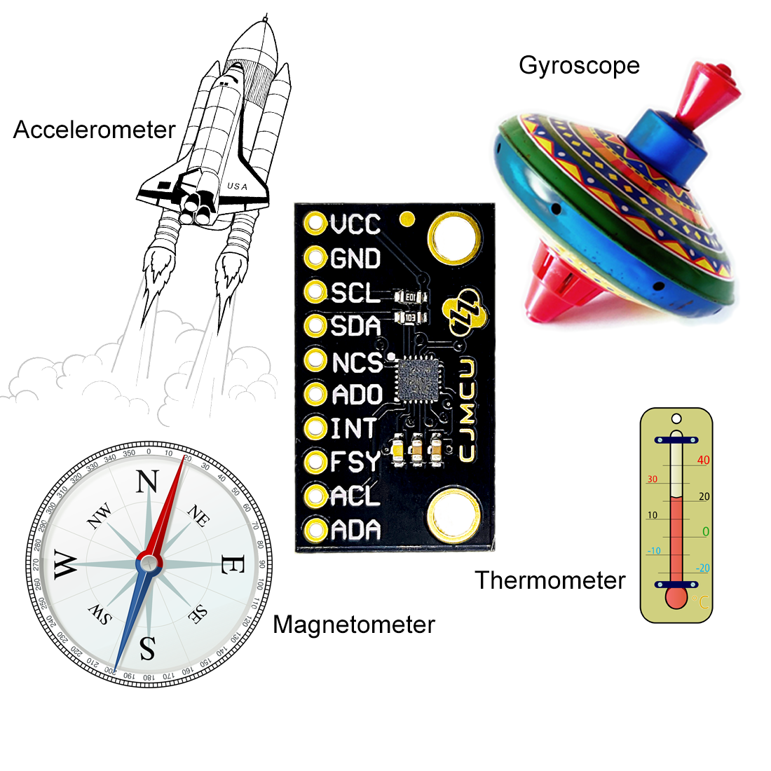
The ICM-20948 is called the 9-axis sensor because it combines three sensors, each covering three axes. It is:
- Accelerometer,
- Gyroscope,
- and magnetometer.
- In addition, the ICM-20948 is equipped with a thermometer.
Such combined sensors are often referred to as IMU for “Inertial Measurement Unit“.
I have already described how gyroscopes and an accelerometers work in my article about the MPU6050. The magnetometer works based on the Hall effect. You find a good explanation here.
The main technical specifications of the ICM-20948 are:
- Power supply (VDD): 1.71 – 3.6 volts
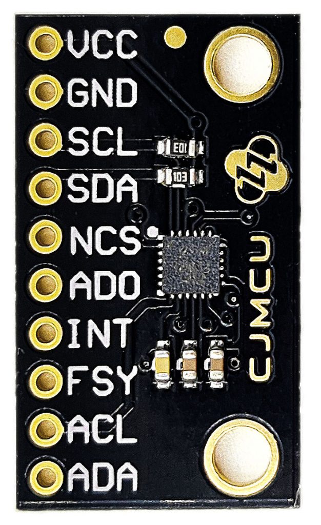
- most modules do not have a voltage regulator
- VDDIO: 1.71 – 1.95 volts
- Tolerance range for I/O pins
- On the module on the right, VDDIO is connected to VDD.
- Communication via I2C, the addresses are:
- AD0 set to LOW: 0x68
- AD0 set to HIGH: 0x69
- Communication via SPI
- Gyroscope:
- Ranges: +/-250, +/-500, +/-1000, +/-2000 °/s
- Data rate: 4.4 Hz – 9 kHz
- Accelerometer:
- Ranges: +/- 2, +/-4, +/-8, +/-16 g
- Data rate: 4.5 Hz – 4.5 kHz
- Magnetometer (AK09916):
- Range: +/- 4900 μT
- max. data rate: 100 Hz
- FIFO (first in, first out) data storage: 512 / 4096 bytes
- Interrupts (the ones I implemented): FIFO overflow, data ready, FSync and “wake-on-motion”
- Integrated thermometer
The ICM-20948 allows the control of up to five additional sensors via an auxiliary I2C interface. The measured values are stored in the registers of the ICM-20948 and read from there.
The magnetometer is not really integrated into the ICM-20948. It has seperate registers and its own I2C address. You can only control it via the auxiliary interface just described. But don’t worry, you don’t have to deal with it because my library takes care for everything in the background.
Further information can be found in the technical data sheetof the ICM-20948 and in the data sheet of the magnetometer AK09916. You can read about the differences between the MPU-9250 and the ICM-20948 here.
Digital Motion Processor DMP
The ICM-20948 offers the possibility to process the data measured by it and other external sensors. That relieves the microcontroller. For this purpose, the ICM-20948 has the so-called Digital Motion ProcessorTM, DMP for short. However, the implementation of the DMP functions would be an effort for me that exceeds my capacities. I have already invested several dozen hours in developing the library.
Controlling the ICM-20948
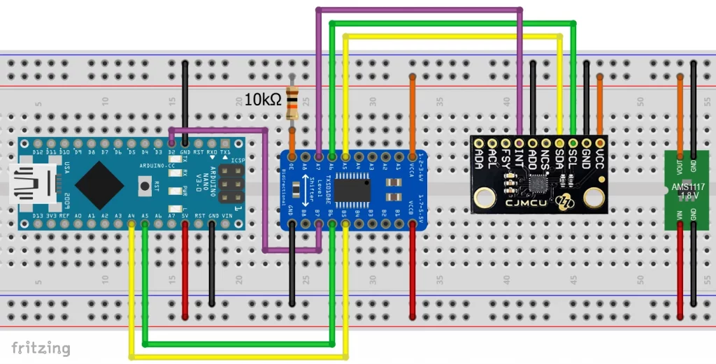
Wiring
When it comes to the power supply, you must ensure that the ICM-20948 can only be operated with up to 3.6 volts. However, this only applies to VDD. The I/O pins and VDDIO can only tolerate 1.71 – 1.95 volts. On some modules (such as the one shown above), VDDIO is implemented together with VDD on the VDD pin. In this case, you may only operate it with 1.71-1.95 volts and must use level shifters for both 5-volt and 3.3-volt boards.
You won’t have these problems with the more expensive boards from Adafruit, SparkFun or Pimoroni, as they are already equipped with the appropriate level shifters.
Connect the address pin AD0 to HIGH (1.71–1.95 V) or GND, depending on which address you want to use. In some example sketches I also use the interrupt pin INT, which I attached to the Arduino pin 2.
Other pins, not used by me:
- ADA and ACL are connections for other sensors that are controlled via the auxiliary I2C interface. I only implemented the auxiliary I2C interface for the magnetometer.
- NCS is the chip select pin for SPI communication.
- You can use FYSYNC as an external interrupt pin. I’ll have an example sketch for this later.
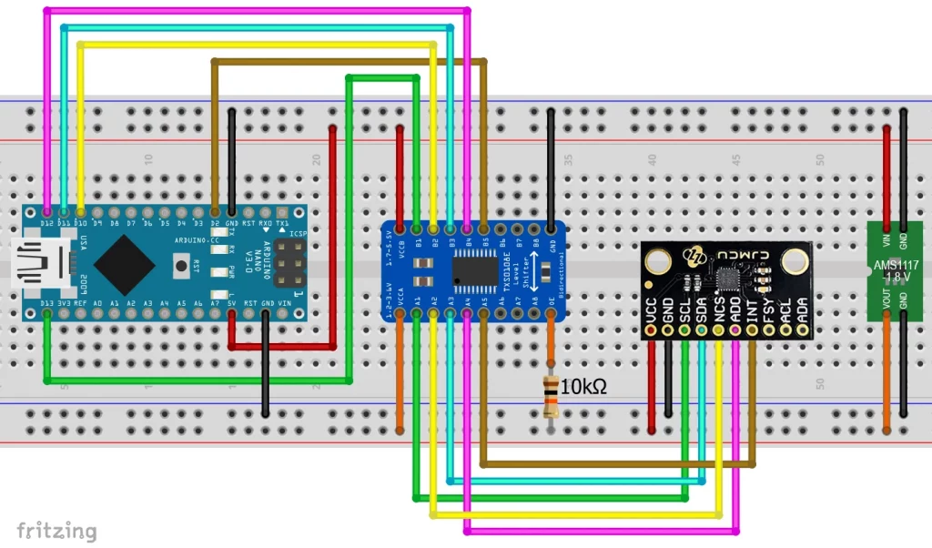
Connection via SPI
I have also implemented faster control via SPI. You can find a sample sketch as part of the library.
ICM-20948, “version 2”
There are also modules with the suffix “Version 2”, “v2” or “v2.0”. They have voltage regulators that reduce the input voltage to 1.8 volts. Unfortunately, not all of them have the necessary level shifters for the digital pins. Here are two examples:
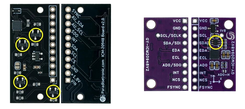
The left module has four MOSFETs for the SDO, SDA, SCL and INT pins. As far as I can tell, the CS pin is unprotected. If you are using SPI, you will need to use a voltage divider. Or you can connect CS to GND if you are only operating one device with the SPI interface.
The right module only has two MOSFETs, which are combined in the marked 6-pin IC. The MOSFETs handle the SDA and SCL levels. This means you can only use it with I2C. However, there is still a problem with INT. Its HIGH level is 1.8 volts, which is not necessarily interpreted as HIGH by the microcontroller. The ADO pin also appears to be unprotected.
Introduction to the ICM20948_WE library
I tried some libraries, but I couldn’t really get excited about any of them. That’s why I wrote my own library, which you can find here on GitHub. Alternatively, you can install it directly using the library manager of the Arduino IDE.
The problem with the ICM-20948 is that it has an incredible number of setting options due to its 4 sensors plus I2C auxiliary interface. And although I haven’t implemented all the functions, my library includes fifty-nine public functions. To explain the use of these functions, I have provided the library with thirteen example sketches.
I will now walk you through the example sketches, which is a pretty dry read. Maybe just try them out and come back here if you don’t understand something.
Determine basic data with the ICM-20948
ICM20948_01_acceleration_data.ino
This first sketch is the one I go into most intensively. Much is repeated in the following sketches.
Before I start, a comment about the data type “xyzFloat”. This is a structure (struct) consisting of three float values. I use xyzFloat for all data that has an x, y, and z component.
#include <Wire.h>
#include <ICM20948_WE.h>
#define ICM20948_ADDR 0x68

/* There are several ways to create your ICM20948 object:
 * ICM20948_WE myIMU = ICM20948_WE()              -> uses Wire / I2C Address = 0x68
 * ICM20948_WE myIMU = ICM20948_WE(ICM20948_ADDR) -> uses Wire / ICM20948_ADDR
 * ICM20948_WE myIMU = ICM20948_WE(&wire2)        -> uses the TwoWire object wire2 / ICM20948_ADDR
 * ICM20948_WE myIMU = ICM20948_WE(&wire2, ICM20948_ADDR) -> all together
 * ICM20948_WE myIMU = ICM20948_WE(CS_PIN, spi);  -> uses SPI, spi is just a flag, see SPI example
 * ICM20948_WE myIMU = ICM20948_WE(&SPI, CS_PIN, spi);  -> uses SPI / passes the SPI object, spi is just a flag, see SPI example
 */
ICM20948_WE myIMU = ICM20948_WE(ICM20948_ADDR);

void setup() {
  //delay(2000); // maybe needed for some MCUs, in particular for startup after power off
  Wire.begin();
  Serial.begin(115200);
  while(!Serial) {}

  if(!myIMU.init()){
    Serial.println("ICM20948 does not respond");
  }
  else{
    Serial.println("ICM20948 is connected");
  }

  /*  This is a method to calibrate. You have to determine the minimum and maximum
   *  raw acceleration values of the axes determined in the range +/- 2 g.
   *  You call the function as follows: setAccOffsets(xMin,xMax,yMin,yMax,zMin,zMax);
   *  The parameters are floats.
   *  The calibration changes the slope / ratio of raw acceleration vs g. The zero point
   *  is set as (min + max)/2.
   */
  //myIMU.setAccOffsets(-16330.0, 16450.0, -16600.0, 16180.0, -16640.0, 16560.0);

  /* The starting point, if you position the ICM20948 flat, is not necessarily 0g/0g/1g for x/y/z.
   * The autoOffset function measures offset. It assumes your ICM20948 is positioned flat with its
   * x,y-plane. The more you deviate from this, the less accurate will be your results.
   * It overwrites the zero points of setAccOffsets, but keeps the correction of the slope.
   * The function also measures the offset of the gyroscope data. The gyroscope offset does not
   * depend on the positioning.
   * This function needs to be called after setAccOffsets but before other settings since
   * it will overwrite settings!
   * You can query the offsets with the functions:
   * xyzFloat getAccOffsets()
   * You can apply the offsets using:
   * setAccOffsets(xyzFloat yourOffsets)
   */
  Serial.println("Position your ICM20948 flat and don't move it - calibrating...");
  delay(1000);
  myIMU.autoOffsets();
  Serial.println("Done!");

  /* enables or disables the acceleration sensor, default: enabled */
  // myIMU.enableAcc(true);

  /*  ICM20948_ACC_RANGE_2G      2 g   (default)
   *  ICM20948_ACC_RANGE_4G      4 g
   *  ICM20948_ACC_RANGE_8G      8 g
   *  ICM20948_ACC_RANGE_16G    16 g
   */
  myIMU.setAccRange(ICM20948_ACC_RANGE_2G);

  /*  Choose a level for the Digital Low Pass Filter or switch it off.
   *  ICM20948_DLPF_0, ICM20948_DLPF_2, ...... ICM20948_DLPF_7, ICM20948_DLPF_OFF
   *
   *  IMPORTANT: This needs to be ICM20948_DLPF_7 if DLPF is used in cycle mode!
   *
   *  DLPF       3dB Bandwidth [Hz]      Output Rate [Hz]
   *    0              246.0               1125/(1+ASRD) (default)
   *    1              246.0               1125/(1+ASRD)
   *    2              111.4               1125/(1+ASRD)
   *    3               50.4               1125/(1+ASRD)
   *    4               23.9               1125/(1+ASRD)
   *    5               11.5               1125/(1+ASRD)
   *    6                5.7               1125/(1+ASRD)
   *    7              473.0               1125/(1+ASRD)
   *    OFF           1209.0               4500
   *
   *    ASRD = Accelerometer Sample Rate Divider (0...4095)
   *    You achieve lowest noise using level 6
   */
  myIMU.setAccDLPF(ICM20948_DLPF_6);

  /*  Acceleration sample rate divider divides the output rate of the accelerometer.
   *  Sample rate = Basic sample rate / (1 + divider)
   *  It can only be applied if the corresponding DLPF is not off!
   *  Divider is a number 0...4095 (different range compared to gyroscope)
   *  If sample rates are set for the accelerometer and the gyroscope, the gyroscope
   *  sample rate has priority.
   */
  myIMU.setAccSampleRateDivider(10);
}

void loop() {
  xyzFloat accRaw;
  xyzFloat corrAccRaw;
  xyzFloat gVal;
  myIMU.readSensor();
  myIMU.getAccRawValues(&accRaw);
  myIMU.getCorrectedAccRawValues(&corrAccRaw);
  myIMU.getGValues(&gVal);
  float resultantG = myIMU.getResultantG(&gVal);


  Serial.println("Raw acceleration values (x,y,z):");
  Serial.print(accRaw.x);
  Serial.print("   ");
  Serial.print(accRaw.y);
  Serial.print("   ");
  Serial.println(accRaw.z);

  Serial.println("Corrected raw acceleration values (x,y,z):");
  Serial.print(corrAccRaw.x);
  Serial.print("   ");
  Serial.print(corrAccRaw.y);
  Serial.print("   ");
  Serial.println(corrAccRaw.z);

  Serial.println("g-values (x,y,z):");
  Serial.print(gVal.x);
  Serial.print("   ");
  Serial.print(gVal.y);
  Serial.print("   ");
  Serial.println(gVal.z);

  Serial.print("Resultant g: ");
  Serial.println(resultantG);
  Serial.println("*************************************");

  delay(1000);
}
Initialization and offsets
I have implemented several constructors. This allows you to pass the I2C address and/or the I2C object. The latter is interesting if, for example, you want to use both I2C interfaces of an ESP32.
The function init() first resets the ICM-20948 and writes default values to some registers. init() returns “false” if the ICM-20948 does not answer, otherwise true.
In the motionless state, only the acceleration due to gravity acts on the ICM-20948. If it is positioned flat (i.e. with its x,y plane), the g value should be zero for the x and y axes and one for the z axis. However, these values are more or less shifted. The function autoOffsets() measures the offset values which are subtracted from future measured values. However, it does not correct the slope.
autoOffsets() works only then reliably,
- if the module lies flat with its x,y plane,
- is not moved, and
- the function is called as the first function in the setup (because it changes certain settings)
Alternatively, you can use the function setAccOffsets(). It leads to less good results regarding the zero point, but it is more accurate at larger angles. In addition, it corrects the slope, and you do not have to position the module flat at program start.
Other settings
The function setAccRange() sets the range for the acceleration measurements.
To control the data rate of the accelerometer, use the function setAccSampleRateDivider(divider).
![\[ \text{acceleration data rate}=\frac{1125}{1+divider}\;[\text{Hz}]\;\;\;\;\;\;\;\;\text{mit}\;\;divider = 0...4095 \]](https://wolles-elektronikkiste.de/wp-content/ql-cache/quicklatex.com-71de542e43adb4511a5f68317d41b18e_l3.png "Rendered by QuickLaTeX.com")
However, this only works if the digital low pass filter (DLPF) is activated. With setAccDLPF(level) you enable the DLPF and select the level. The parameter ICM20948_DLPF_OFF disables the DLPF. The higher the level, the lower the noise. Only level 7 does not fit in this series in this respect. The disadvantage of strong noise reduction is reduced response time. This means that when the acceleration changes, it takes a while for the MPU9250 to output the correct value.
With enableAcc(true/false) you can switch the accelerometer on or off.
The results
You can query the measured values with the following functions:
readSensor()reads the data registers in burst method (i.e. “in one go”) and writes the result to a buffer array.- Without a previous call of
readSensor(), you will not get updated values.
- Without a previous call of
getAccRawValues()provides the raw values of the acceleration in the ICM-20948 data register.getCorrectedAccRawValues()reads the raw values and corrects them for the offsets.getGValues()provides the acceleration values in g (based on the corrected raw data).getResultantG(gValue)calculates the resulting acceleration from a g-value triple, i.e. the absolute value of the sum of the three vectors.
![\[ \text{resultantG}=\sqrt{(gValue.x)^2+(gValue.y)^2+(gValue.z)^2} \;\;\text{[g]} \]](https://wolles-elektronikkiste.de/wp-content/ql-cache/quicklatex.com-e415876d0493a2aebdb57079133d69fc_l3.png "Rendered by QuickLaTeX.com")
If only gravity acts on the ICM-20948, the resultant should always be 1. With the resultant function, you can easily measure accelerations without having to align the movement to one axis. Simply subtract 1 to compensate for gravity.
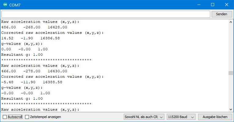
The output of ICM20948_01_acceleration_data.ino
ICM20948_02_gyroscope_data.ino
Since you already know some functions, the explanation of the gyroscope sketch can be much shorter.
#include <Wire.h>
#include <ICM20948_WE.h>
#define ICM20948_ADDR 0x68

/* There are several ways to create your ICM20948 object:
 * ICM20948_WE myIMU = ICM20948_WE()              -> uses Wire / I2C Address = 0x68
 * ICM20948_WE myIMU = ICM20948_WE(ICM20948_ADDR) -> uses Wire / ICM20948_ADDR
 * ICM20948_WE myIMU = ICM20948_WE(&wire2)        -> uses the TwoWire object wire2 / ICM20948_ADDR
 * ICM20948_WE myIMU = ICM20948_WE(&wire2, ICM20948_ADDR) -> all together
 * ICM20948_WE myIMU = ICM20948_WE(CS_PIN, spi);  -> uses SPI, spi is just a flag, see SPI example
 * ICM20948_WE myIMU = ICM20948_WE(&SPI, CS_PIN, spi);  -> uses SPI / passes the SPI object, spi is just a flag, see SPI example
 */
ICM20948_WE myIMU = ICM20948_WE(ICM20948_ADDR);

void setup() {
  //delay(2000); // maybe needed for some MCUs, in particular for startup after power off
  Wire.begin();
  Serial.begin(115200);
  while(!Serial) {}

  if(!myIMU.init()){
    Serial.println("ICM20948 does not respond");
  }
  else{
    Serial.println("ICM20948 is connected");
  }

  Serial.println("Position your ICM20948 flat and don't move it - calibrating...");
  delay(1000);
  myIMU.autoOffsets();
  Serial.println("Done!");

  /*  The gyroscope data is not zero, even if you don't move the ICM20948.
   *  To start at zero, you can apply offset values. These are the gyroscope raw values you obtain
   *  using the +/- 250 degrees/s range.
   *  Use either autoOffsets or setGyrOffsets, not both.
   *  You can query the offsets with the function:
   *  xyzFloat getGyrOffsets()
  */
  //myIMU.setGyrOffsets(-115.0, 130.0, 105.0);

  /* enables or disables the gyroscope sensor, default: enabled */
  // myIMU.enableGyr(false);

  /*  ICM20948_GYRO_RANGE_250       250 degrees per second (default)
   *  ICM20948_GYRO_RANGE_500       500 degrees per second
   *  ICM20948_GYRO_RANGE_1000     1000 degrees per second
   *  ICM20948_GYRO_RANGE_2000     2000 degrees per second
   */
  myIMU.setGyrRange(ICM20948_GYRO_RANGE_250);

  /*  Choose a level for the Digital Low Pass Filter or switch it off.
   *  ICM20948_DLPF_0, ICM20948_DLPF_2, ...... ICM20948_DLPF_7, ICM20948_DLPF_OFF
   *
   *  DLPF       3dB Bandwidth [Hz]      Output Rate [Hz]
   *    0              196.6               1125/(1+GSRD)
   *    1              151.8               1125/(1+GSRD)
   *    2              119.5               1125/(1+GSRD)
   *    3               51.2               1125/(1+GSRD)
   *    4               23.9               1125/(1+GSRD)
   *    5               11.6               1125/(1+GSRD)
   *    6                5.7               1125/(1+GSRD)
   *    7              361.4               1125/(1+GSRD)
   *    OFF          12106.0               9000
   *
   *    GSRD = Gyroscope Sample Rate Divider (0...255)
   *    You achieve lowest noise using level 6
   */
  myIMU.setGyrDLPF(ICM20948_DLPF_6);

  /*  Gyroscope sample rate divider divides the output rate of the gyroscope.
   *  Sample rate = Basic sample rate / (1 + divider)
   *  It can only be applied if the corresponding DLPF is not OFF!
   *  Divider is a number 0...255
   *  If sample rates are set for the accelerometer and the gyroscope, the gyroscope
   *  sample rate has priority.
   */
  //myIMU.setGyrSampleRateDivider(10);
}

void loop() {
  xyzFloat gyrRaw;
  xyzFloat gyr;
  myIMU.readSensor();
  myIMU.getCorrectedGyrRawValues(&gyrRaw);
  myIMU.getGyrValues(&gyr);

  Serial.println("Raw gyroscope values (x,y,z):");
  Serial.print(gyrRaw.x);
  Serial.print("   ");
  Serial.print(gyrRaw.y);
  Serial.print("   ");
  Serial.println(gyrRaw.z);

  Serial.println("Gyroscope values (x,y,z):");
  Serial.print(gyr.x);
  Serial.print("   ");
  Serial.print(gyr.y);
  Serial.print("   ");
  Serial.println(gyr.z);
  Serial.println();

  delay(500);
}
Again, you can use the autoOffsets() function. The gyroscope should indicate zero or at least fluctuate around zero for all axes in the motionless state. However, you will notice some offset that is independent of the orientation. Alternatively, apply the values determined in the measuring range +/-250 °/s in setGyrOffsets(). I’ll come back to that in the section of the calibration sketch.
You activate the low-pass filter (DLPF) with setGyrDLPF(value) and set the level. Here, too, a stronger filter leads to reduced reaction speed. Level 7 is an exception in this respect. ICM20948_DLPF_OFF disables the DLPF.
Other features:
setGyrSampleRateDivider()works similar to the accelerometer.setGyrRange()defines the measuring range.enableGyr(true/false)enables or disables the gyroscope.getGyrRawValues()returns the currently available raw data.getCorrectedGyrRawValues()subtracts the offsets from the raw data and returns the corrected data.getGyrValues()provides the gyroscope data in degrees/second, based on the corrected raw data.
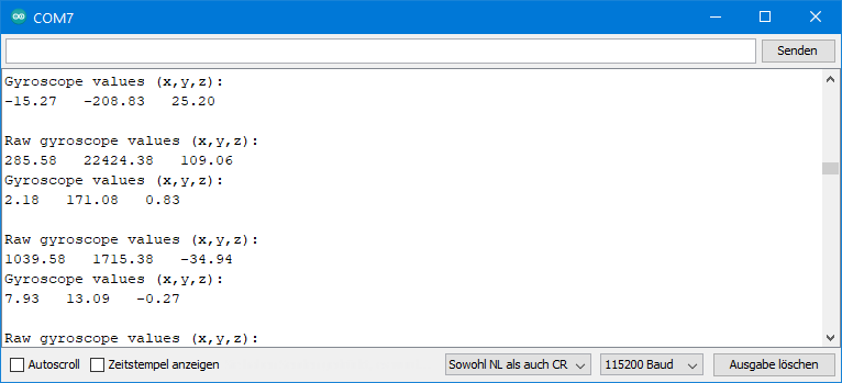
The output of ICM20948_02_gyroscope_data.ino
ICM20948_03_magnetometer.ino
The magnetometer (AK09916) behaves like a separate component. It has its own I2C address, own registers and must therefore be initialized separately. If you apply an I2C scanner to the ICM-20948, you won’t detect the magnetometer. The magnetometer is not directly accessible, it is behind the ICM-20948, so to speak. You control it via the auxiliary I2C interface described above, which is provided by the ICM-20948. However, you won’t notice any of this, as the library manages everything in the background.
#include <Wire.h>
#include <ICM20948_WE.h>
#define ICM20948_ADDR 0x68

/* There are several ways to create your ICM20948 object:
 * ICM20948_WE myIMU = ICM20948_WE()              -> uses Wire / I2C Address = 0x68
 * ICM20948_WE myIMU = ICM20948_WE(ICM20948_ADDR) -> uses Wire / ICM20948_ADDR
 * ICM20948_WE myIMU = ICM20948_WE(&wire2)        -> uses the TwoWire object wire2 / ICM20948_ADDR
 * ICM20948_WE myIMU = ICM20948_WE(&wire2, ICM20948_ADDR) -> all together
 * ICM20948_WE myIMU = ICM20948_WE(CS_PIN, spi);  -> uses SPI, spi is just a flag, see SPI example
 * ICM20948_WE myIMU = ICM20948_WE(&SPI, CS_PIN, spi);  -> uses SPI / passes the SPI object, spi is just a flag, see SPI example
 */
ICM20948_WE myIMU = ICM20948_WE(ICM20948_ADDR);

void setup() {
  //delay(2000); // maybe needed for some MCUs, in particular for startup after power off
  Wire.begin();
  Serial.begin(115200);
  while (!Serial) {}

  if (!myIMU.init()) {
    Serial.println("ICM20948 does not respond");
  }
  else {
    Serial.println("ICM20948 is connected");
  }

  if (!myIMU.initMagnetometer()) {
    Serial.println("Magnetometer does not respond");
  }
  else {
    Serial.println("Magnetometer is connected");
  }

  /* You can set the following modes for the magnetometer:
   * AK09916_PWR_DOWN          Power down to save energy
   * AK09916_TRIGGER_MODE      Measurements on request, a measurement is triggered by
   *                           calling setMagOpMode(AK09916_TRIGGER_MODE)
   * AK09916_CONT_MODE_10HZ    Continuous measurements, 10 Hz rate
   * AK09916_CONT_MODE_20HZ    Continuous measurements, 20 Hz rate
   * AK09916_CONT_MODE_50HZ    Continuous measurements, 50 Hz rate
   * AK09916_CONT_MODE_100HZ   Continuous measurements, 100 Hz rate (default)
   */
  myIMU.setMagOpMode(AK09916_CONT_MODE_20HZ);
  // delay(50); // add a delay of 1000/magRate to avoid first mag value being zero
}

void loop() {
  xyzFloat magValue; // x/y/z magnetic flux density [µT]
  myIMU.readSensor();
  myIMU.getMagValues(&magValue);

  Serial.println("Magnetometer Data in µTesla: ");
  Serial.print(magValue.x);
  Serial.print("   ");
  Serial.print(magValue.y);
  Serial.print("   ");
  Serial.println(magValue.z);

  delay(1000);
}
Magnetometer settings
The magnetometer has a power-down mode, a trigger mode and four continuous modes. The continuous modes differ in data rate, namely 10, 20, 40 or 100 Hz. The mode is set with setMagOpMode().
You retrieve the measured values with getMagValues(). The result is output in microtesla. The function returns the values that are currently in the data buffer. Before that, you have to call readSensor() to update the data buffer with the latest sensor data.
In trigger mode, a measurement is initiated with setMagOpMode(AK09916_TRIGGER_MODE). If you choose this option, you must give the magnetometer enough time to perform the measurement and transmit the data to the ICM-20948 data registers.
The output of ICM20948_03_magnetometer.ino
For the following output, I rotated the ICM-20948 flat in its x,y plane:
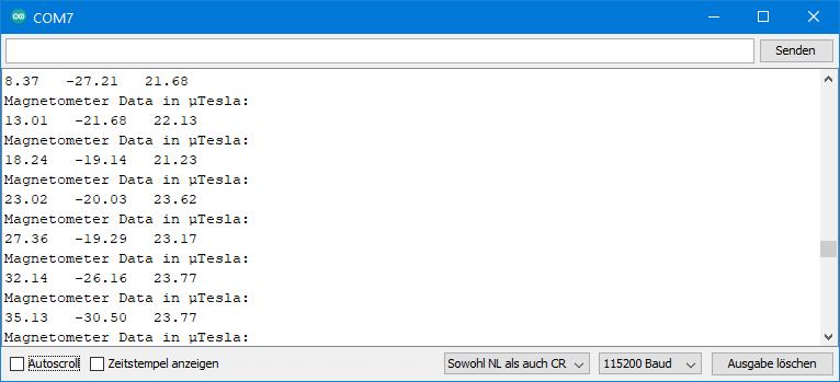
In Central Europe, the magnetic flux density of the Earth’s magnetic field is about 20 microns in the horizontal and around 44 µT in the vertical (source: German Wikipedia). Accordingly, the difference between the maximum and minimum value for rotation in the horizontal or vertical should be 40 and 88 μT respectively. You probably won’t measure that values because:
- Again, there are offsets.
- You are probably measuring indoors, and depending on the construction of the building, the Earth’s magnetic field is shielded.
- When measuring on a breadboard, the jumper cables and metal inside the breadboard will influence the measurements.
ICM20948_04_calibration.ino
This sketch is designed to help you determine the offsets for the accelerometer and gyroscope. To do this, first set the lowest measuring range and the maximum low-pass filter. This ensures high resolution and low noise.
For the offset determination of the accelerometer, turn the ICM-20948 slowly (!) around its axes and note the maximum and minimum raw values. It is best to have your elbows on the table when doing this, as any shaking will result in additional acceleration. You then use this data for the setAccOffsets() function. Internally, the offsets are determined from this. When you change the measuring range, the offsets are automatically adjusted. With this method you are no longer dependent on the level orientation of the ICM-20948 at program start. For the determination of precise small angles, however, I still recommend the autoOffsets() function.
For the gyroscope offsets you do not need to rotate the ICM-20948 because the offset is independent of the inclination. You apply the values for the x-, y- and z-axis as parameters in setGyrOffsets().
#include <Wire.h>
#include <ICM20948_WE.h>
#define ICM20948_ADDR 0x68

/* There are several ways to create your ICM20948 object:
 * ICM20948_WE myIMU = ICM20948_WE()              -> uses Wire / I2C Address = 0x68
 * ICM20948_WE myIMU = ICM20948_WE(ICM20948_ADDR) -> uses Wire / ICM20948_ADDR
 * ICM20948_WE myIMU = ICM20948_WE(&wire2)        -> uses the TwoWire object wire2 / ICM20948_ADDR
 * ICM20948_WE myIMU = ICM20948_WE(&wire2, ICM20948_ADDR) -> all together
 * ICM20948_WE myIMU = ICM20948_WE(CS_PIN, spi);  -> uses SPI, spi is just a flag, see SPI example
 * ICM20948_WE myIMU = ICM20948_WE(&SPI, CS_PIN, spi);  -> uses SPI / passes the SPI object, spi is just a flag, see SPI example
 */
ICM20948_WE myIMU = ICM20948_WE(ICM20948_ADDR);

void setup() {
  //delay(2000); // maybe needed for some MCUs, in particular for startup after power off
  Wire.begin();
  Serial.begin(115200);
  while(!Serial) {}

  if(!myIMU.init()){
    Serial.println("ICM20948 does not respond");
  }
  else{
    Serial.println("ICM20948 is connected");
  }

  /*  This is a method to calibrate. You have to determine the minimum and maximum
   *  raw acceleration values of the axes determined in the range +/- 2 g.
   *  You call the function as follows: setAccOffsets(xMin,xMax,yMin,yMax,zMin,zMax);
   *  The parameters are floats.
   *  The calibration changes the slope / ratio of raw accleration vs g. The zero point is
   *  set as (min + max)/2.
   */
  myIMU.setAccOffsets(-16330.0, 16450.0, -16600.0, 16180.0, -16520.0, 16690.0);

  /*  The gyroscope data is not zero, even if you don't move the ICM20948.
   *  To start at zero, you can apply offset values. These are the gyroscope raw values you obtain
   *  using the +/- 250 degrees/s range.
   *  Use either autoOffset or setGyrOffsets, not both.
   */
  myIMU.setGyrOffsets(-115.0, 130.0, 105.0);

  /*  ICM20948_ACC_RANGE_2G      2 g   (default)
   *  ICM20948_ACC_RANGE_4G      4 g
   *  ICM20948_ACC_RANGE_8G      8 g
   *  ICM20948_ACC_RANGE_16G    16 g
   */
  myIMU.setAccRange(ICM20948_ACC_RANGE_2G); // highest res for calibration

  /*  Choose a level for the Digital Low Pass Filter or switch it off.
   *  ICM20948_DLPF_0, ICM20948_DLPF_2, ...... ICM20948_DLPF_7, ICM20948_DLPF_OFF
   *
   *  IMPORTANT: This needs to be ICM20948_DLPF_7 if DLPF is used in cycle mode!
   *
   *  DLPF       3dB Bandwidth [Hz]      Output Rate [Hz]
   *    0              246.0               1125/(1+ASRD)
   *    1              246.0               1125/(1+ASRD)
   *    2              111.4               1125/(1+ASRD)
   *    3               50.4               1125/(1+ASRD)
   *    4               23.9               1125/(1+ASRD)
   *    5               11.5               1125/(1+ASRD)
   *    6                5.7               1125/(1+ASRD)
   *    7              473.0               1125/(1+ASRD)
   *    OFF           1209.0               4500
   *
   *    ASRD = Accelerometer Sample Rate Divider (0...4095)
   *    You achieve lowest noise using level 6
   */
  myIMU.setAccDLPF(ICM20948_DLPF_6); // lowest noise for calibration

  /*  ICM20948_GYRO_RANGE_250       250 degrees per second (default)
   *  ICM20948_GYRO_RANGE_500       500 degrees per second
   *  ICM20948_GYRO_RANGE_1000     1000 degrees per second
   *  ICM20948_GYRO_RANGE_2000     2000 degrees per second
   */
  myIMU.setGyrRange(ICM20948_GYRO_RANGE_250); //highest resolution for calibration

  /*  Choose a level for the Digital Low Pass Filter or switch it off.
   *  ICM20948_DLPF_0, ICM20948_DLPF_2, ...... ICM20948_DLPF_7, ICM20948_DLPF_OFF
   *
   *  DLPF       3dB Bandwidth [Hz]      Output Rate [Hz]
   *    0              196.6               1125/(1+GSRD)
   *    1              151.8               1125/(1+GSRD)
   *    2              119.5               1125/(1+GSRD)
   *    3               51.2               1125/(1+GSRD)
   *    4               23.9               1125/(1+GSRD)
   *    5               11.6               1125/(1+GSRD)
   *    6                5.7               1125/(1+GSRD)
   *    7              361.4               1125/(1+GSRD)
   *    OFF          12106.0               9000
   *
   *    GSRD = Gyroscope Sample Rate Divider (0...255)
   *    You achieve lowest noise using level 6
   */
  myIMU.setGyrDLPF(ICM20948_DLPF_6); // lowest noise for calibration

  /*  Choose a level for the Digital Low Pass Filter.
   *  ICM20948_DLPF_0, ICM20948_DLPF_2, ...... ICM20948_DLPF_7, ICM20948_DLPF_OFF
   *
   *  DLPF          Bandwidth [Hz]      Output Rate [Hz]
   *    0             7932.0                    9
   *    1              217.9                 1125
   *    2              123.5                 1125
   *    3               65.9                 1125
   *    4               34.1                 1125
   *    5               17.3                 1125
   *    6                8.8                 1125
   *    7             7932.0                    9
   *
   *
   *    GSRD = Gyroscope Sample Rate Divider (0...255)
   *    You achieve lowest noise using level 6
   */
  myIMU.setTempDLPF(ICM20948_DLPF_6); // lowest noise for calibration
}

void loop() {
  xyzFloat accRaw;
  xyzFloat gyrRaw;
  xyzFloat corrAccRaw;
  xyzFloat corrGyrRaw;
  xyzFloat gVal;
  myIMU.readSensor();
  myIMU.getAccRawValues(&accRaw);
  myIMU.getGyrRawValues(&gyrRaw);
  myIMU.getCorrectedAccRawValues(&corrAccRaw);
  myIMU.getCorrectedGyrRawValues(&corrGyrRaw);
  myIMU.getGValues(&gVal);

  Serial.println("Acceleration raw values without offset:");
  Serial.print(accRaw.x);
  Serial.print("   ");
  Serial.print(accRaw.y);
  Serial.print("   ");
  Serial.println(accRaw.z);

  Serial.println("Gyroscope raw values without offset:");
  Serial.print(gyrRaw.x);
  Serial.print("   ");
  Serial.print(gyrRaw.y);
  Serial.print("   ");
  Serial.println(gyrRaw.z);

  Serial.println("Acceleration raw values with offset:");
  Serial.print(corrAccRaw.x);
  Serial.print("   ");
  Serial.print(corrAccRaw.y);
  Serial.print("   ");
  Serial.println(corrAccRaw.z);

  Serial.println("Gyroscope raw values with offset:");
  Serial.print(corrGyrRaw.x);
  Serial.print("   ");
  Serial.print(corrGyrRaw.y);
  Serial.print("   ");
  Serial.println(corrGyrRaw.z);

  Serial.println("g-values, based on corrected raws (x,y,z):");
  Serial.print(gVal.x);
  Serial.print("   ");
  Serial.print(gVal.y);
  Serial.print("   ");
  Serial.println(gVal.z);


  Serial.println("********************************************");

  delay(500);
}
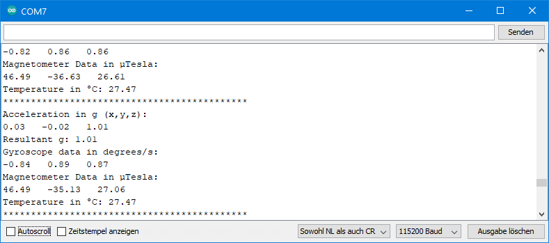
All together: ICM20948_05_acc_gyr_temp_mag_data.ino
Using this sketch, you can determine the acceleration, gyroscope values, magnetometer values and temperature. You query the temperature with getTemperature(). I have already explained all other functions. You can find the sketch in the examples.
The thermometer is not so much used to measure the ambient temperature as to track the temperature in the ICM-20948. It is higher than the room temperature and increases in operation depending on the measurement conditions.
The output of ICM20948_05_acc_gyr_temp_mag_data.ino
How to measure angles with the ICM-20948
You can use the (earth) acceleration data to calculate tilt angles. You have to make sure that no additional acceleration acts on the ICM-20948. I have implemented two methods for this.
ICM20948_06_angles_and_orientation.ino
With the method presented in this sketch, the angle α between the axes and the horizontal is calculated quite simply from the arcussine of the acceleration value.
![\[ \alpha=\arcsin(\text{g-Wert}) \]](https://wolles-elektronikkiste.de/wp-content/ql-cache/quicklatex.com-40230c45220cd74948b1272b34862579_l3.png "Rendered by QuickLaTeX.com")
For small angles this works perfectly, at larger angles the error increases. Why this is the case, I explained in my article about the MMA7361. Up to 60°, the deviation in my experiments was less than one degree.
For this sketch, I recommend to use autoOffset(). With this function, you start at an angle of 0° for the x- and y-axis. For the z-axis you get a starting value around 90°. Since this is a large angle, the z-axis angle fluctuates strongly. For the tilt angles, you will only get reasonable values if you position the ICM-20948 flat for calibration.
#include <Wire.h>
#include <ICM20948_WE.h>
#define ICM20948_ADDR 0x68

/* There are several ways to create your ICM20948 object:
 * ICM20948_WE myIMU = ICM20948_WE()              -> uses Wire / I2C Address = 0x68
 * ICM20948_WE myIMU = ICM20948_WE(ICM20948_ADDR) -> uses Wire / ICM20948_ADDR
 * ICM20948_WE myIMU = ICM20948_WE(&wire2)        -> uses the TwoWire object wire2 / ICM20948_ADDR
 * ICM20948_WE myIMU = ICM20948_WE(&wire2, ICM20948_ADDR) -> all together
 * ICM20948_WE myIMU = ICM20948_WE(CS_PIN, spi);  -> uses SPI, spi is just a flag, see SPI example
 * ICM20948_WE myIMU = ICM20948_WE(&SPI, CS_PIN, spi);  -> uses SPI / passes the SPI object, spi is just a flag, see SPI example
 */
ICM20948_WE myIMU = ICM20948_WE(ICM20948_ADDR);

void setup() {
  //delay(2000); // maybe needed for some MCUs, in particular for startup after power off
  Wire.begin();
  Serial.begin(115200);
  while(!Serial) {}

  if(!myIMU.init()){
    Serial.println("ICM20948 does not respond");
  }
  else{
    Serial.println("ICM20948 is connected");
  }

  /*  This is a method to calibrate. You have to determine the minimum and maximum
   *  raw acceleration values of the axes determined in the range +/- 2 g.
   *  You call the function as follows: setAccOffsets(xMin,xMax,yMin,yMax,zMin,zMax);
   *  The parameters are floats.
   *  The calibration changes the slope / ratio of raw acceleration vs g. The zero point is
   *  set as (min + max)/2.
   */
  //myIMU.setAccOffsets(-16330.0, 16450.0, -16600.0, 16180.0, -16520.0, 16690.0);

  /* The starting point, if you position the ICM20948 flat, is not necessarily 0g/0g/1g for x/y/z.
   * The autoOffset function measures offset. It assumes your ICM20948 is positioned flat with its
   * x,y-plane. The more you deviate from this, the less accurate will be your results.
   * It overwrites the zero points of setAccOffsets, but keeps the correction of the slope.
   * The function also measures the offset of the gyroscope data. The gyroscope offset does not
   * depend on the positioning.
   * This function needs to be called after setAccOffsets but before other settings since
   * it will overwrite settings!
   * You can query the offsets with the function:
   * xyzFloat getAccOffsets()
   * You can apply the offset using:
   * setAccOffsets(xyzFloat yourOffsets)
   */
  Serial.println("Position your ICM20948 flat and don't move it - calibrating...");
  delay(1000);
  myIMU.autoOffsets();
  Serial.println("Done!");

  /* enables or disables the acceleration sensor, default: enabled */
  // myIMU.enableAcc(true);

  /*  ICM20948_ACC_RANGE_2G      2 g   (default)
   *  ICM20948_ACC_RANGE_4G      4 g
   *  ICM20948_ACC_RANGE_8G      8 g
   *  ICM20948_ACC_RANGE_16G    16 g
   */
  myIMU.setAccRange(ICM20948_ACC_RANGE_2G);

  /*  Choose a level for the Digital Low Pass Filter or switch it off.
   *  ICM20948_DLPF_0, ICM20948_DLPF_2, ...... ICM20948_DLPF_7, ICM20948_DLPF_OFF
   *
   *  IMPORTANT: This needs to be ICM20948_DLPF_7 if DLPF is used in cycle mode!
   *
   *  DLPF       3dB Bandwidth [Hz]      Output Rate [Hz]
   *    0              246.0               1125/(1+ASRD)
   *    1              246.0               1125/(1+ASRD)
   *    2              111.4               1125/(1+ASRD)
   *    3               50.4               1125/(1+ASRD)
   *    4               23.9               1125/(1+ASRD)
   *    5               11.5               1125/(1+ASRD)
   *    6                5.7               1125/(1+ASRD)
   *    7              473.0               1125/(1+ASRD)
   *    OFF           1209.0               4500
   *
   *    ASRD = Accelerometer Sample Rate Divider (0...4095)
   *    You achieve lowest noise using level 6
   */
  myIMU.setAccDLPF(ICM20948_DLPF_6);

  /*  Acceleration sample rate divider divides the output rate of the accelerometer.
   *  Sample rate = Basic sample rate / (1 + divider)
   *  It can only be applied if the corresponding DLPF is not off!
   *  Divider is a number 0...4095 (different range compared to gyroscope)
   *  If sample rates are set for the accelerometer and the gyroscope, the gyroscope
   *  sample rate has priority.
   */
  myIMU.setAccSampleRateDivider(10);
}

void loop() {
  xyzFloat gValue;
  xyzFloat angle;
  myIMU.readSensor();
  myIMU.getGValues(&gValue);
  myIMU.getAngles(&angle);

/* For g-values the corrected raws are used */
  Serial.print("g-x      = ");
  Serial.print(gValue.x);
  Serial.print("  |  g-y      = ");
  Serial.print(gValue.y);
  Serial.print("  |  g-z      = ");
  Serial.println(gValue.z);

/* Angles are also based on the corrected raws. Angles are simply calculated by
   angle = arcsin(g Value) */
  Serial.print("Angle x  = ");
  Serial.print(angle.x);
  Serial.print("  |  Angle y  = ");
  Serial.print(angle.y);
  Serial.print("  |  Angle z  = ");
  Serial.println(angle.z);

  Serial.print("Orientation of the module: ");
  Serial.println(myIMU.getOrientationAsString());

  delay(1000);
}
The following functions are added here:
getAngles()returns the angle of the x, y, and z axes to the horizontal in degrees.- g-values above 1 are truncated to 1 because the arc sine function is not defined for larger values.
getOrientationAsString()indicates which axis has the largest positive angle.- Possible return values are: x up, x down, y up, y down, z up, z down.
- An alternative is
getOrientation(). The return value is an enum (ICM20948_orientation). For the definition look in ICM20948_WE.h.
Output of ICM20948_06_angles_and_orientation.ino
For the following output I have rotated the module around the y-axis, i.e. I have erected the x-axis.

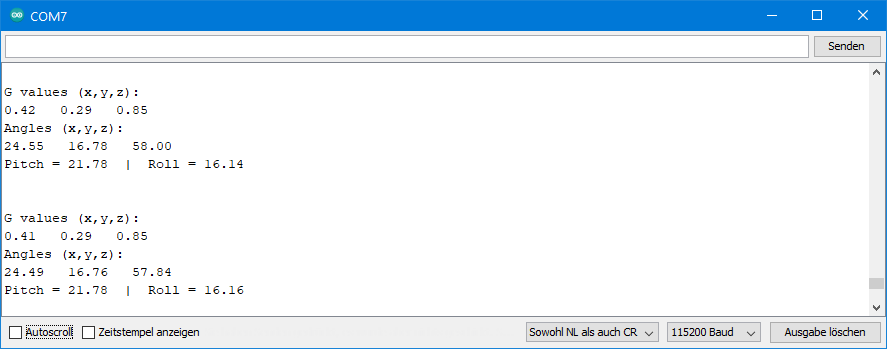
ICM20948_07_pitch_and_roll.ino
This method uses multiple axes to calculate the angles. As a result, the values are more accurate at large angles than with the simple arc sine method. On the other hand, at small angles, the latter method is preferable. To delineate the method, I used the nomenclature of other libraries and referred to the x-axis tilt angle as “pitch” and the y-axis tilt angle as “roll angle”. You can find a definition here, for example.
![\[ pitch\; angle= \arctan \left(\frac{-g_x}{\sqrt{g_y^2 +g_z^2}}\right) \]](https://wolles-elektronikkiste.de/wp-content/ql-cache/quicklatex.com-fe5dff7e366ac98e2576b38fdf36d048_l3.png "Rendered by QuickLaTeX.com")
![\[ roll\;angle = \arctan\left( \frac{g_y}{g_z} \right) \]](https://wolles-elektronikkiste.de/wp-content/ql-cache/quicklatex.com-9820af5f8281ad481115acad0b2fafcb_l3.png "Rendered by QuickLaTeX.com")
For comparison, I use both methods in this sketch. Try it out and choose what suits you more.
#include <Wire.h>
#include <ICM20948_WE.h>
#define ICM20948_ADDR 0x68

/* There are several ways to create your ICM20948 object:
 * ICM20948_WE myIMU = ICM20948_WE()              -> uses Wire / I2C Address = 0x68
 * ICM20948_WE myIMU = ICM20948_WE(ICM20948_ADDR) -> uses Wire / ICM20948_ADDR
 * ICM20948_WE myIMU = ICM20948_WE(&wire2)        -> uses the TwoWire object wire2 / ICM20948_ADDR
 * ICM20948_WE myIMU = ICM20948_WE(&wire2, ICM20948_ADDR) -> all together
 * ICM20948_WE myIMU = ICM20948_WE(CS_PIN, spi);  -> uses SPI, spi is just a flag, see SPI example
 * ICM20948_WE myIMU = ICM20948_WE(&SPI, CS_PIN, spi);  -> uses SPI / passes the SPI object, spi is just a flag, see SPI example
 */
ICM20948_WE myIMU = ICM20948_WE(ICM20948_ADDR);

void setup() {
  //delay(2000); // maybe needed for some MCUs, in particular for startup after power off
  Wire.begin();
  Serial.begin(115200);
  while(!Serial) {}

  if(!myIMU.init()){
    Serial.println("ICM20948 does not respond");
  }
  else{
    Serial.println("ICM20948 is connected");
  }

  /*  This is a method to calibrate. You have to determine the minimum and maximum
   *  raw acceleration values of the axes determined in the range +/- 2 g.
   *  You call the function as follows: setAccOffsets(xMin,xMax,yMin,yMax,zMin,zMax);
   *  The parameters are floats.
   *  The calibration changes the slope / ratio of raw acceleration vs g. The zero point
   *  is set as (min + max)/2.
   */
  //myIMU.setAccOffsets(-16330.0, 16450.0, -16600.0, 16180.0, -16520.0, 16690.0);

  /* The starting point, if you position the ICM20948 flat, is not necessarily 0g/0g/1g for x/y/z.
   * The autoOffset function measures offset. It assumes your ICM20948 is positioned flat with its
   * x,y-plane. The more you deviate from this, the less accurate will be your results.
   * It overwrites the zero points of setAccOffsets, but keeps the correction of the slope.
   * The function also measures the offset of the gyroscope data. The gyroscope offset does not
   * depend on the positioning.
   * This function needs to be called after setAccsOffsets but before other settings since it will
   * overwrite settings!
   * You can query the offsets with the functions:
   * xyzFloat getAccOffsets() and xyzFloat getGyrOffsets()
   * You can apply the offsets using:
   * setAccOffsets(xyzFloat yourOffsets) and setGyrOffsets(xyzFloat yourOffsets)
   */
  Serial.println("Position your ICM20948 flat and don't move it - calibrating...");
  delay(1000);
  myIMU.autoOffsets();
  Serial.println("Done!");

  /* enables or disables the acceleration sensor, default: enabled */
  // myIMU.enableAcc(true);

  /*  ICM20948_ACC_RANGE_2G      2 g   (default)
   *  ICM20948_ACC_RANGE_4G      4 g
   *  ICM20948_ACC_RANGE_8G      8 g
   *  ICM20948_ACC_RANGE_16G    16 g
   */
  myIMU.setAccRange(ICM20948_ACC_RANGE_2G);

  /*  Choose a level for the Digital Low Pass Filter or switch it off.
   *  ICM20948_DLPF_0, ICM20948_DLPF_2, ...... ICM20948_DLPF_7, ICM20948_DLPF_OFF
   *
   *  IMPORTANT: This needs to be ICM20948_DLPF_7 if DLPF is used in cycle mode!
   *
   *  DLPF       3dB Bandwidth [Hz]      Output Rate [Hz]
   *    0              246.0               1125/(1+ASRD)
   *    1              246.0               1125/(1+ASRD)
   *    2              111.4               1125/(1+ASRD)
   *    3               50.4               1125/(1+ASRD)
   *    4               23.9               1125/(1+ASRD)
   *    5               11.5               1125/(1+ASRD)
   *    6                5.7               1125/(1+ASRD)
   *    7              473.0               1125/(1+ASRD)
   *    OFF           1209.0               4500
   *
   *    ASRD = Accelerometer Sample Rate Divider (0...4095)
   *    You achieve lowest noise using level 6
   */
  myIMU.setAccDLPF(ICM20948_DLPF_6);

  /*  Acceleration sample rate divider divides the output rate of the accelerometer.
   *  Sample rate = Basic sample rate / (1 + divider)
   *  It can only be applied if the corresponding DLPF is not off!
   *  Divider is a number 0...4095 (different range compared to gyroscope)
   *  If sample rates are set for the accelerometer and the gyroscope, the gyroscope
   *  sample rate has priority.
   */
  //myIMU.setAccSampleRateDivider(10);
}

void loop() {
  xyzFloat gValue;
  xyzFloat angle;
  myIMU.readSensor();
  myIMU.getGValues(&gValue);
  myIMU.getAngles(&angle);

  float pitch = myIMU.getPitch();
  float roll  = myIMU.getRoll();

  Serial.println("G values (x,y,z):");
  Serial.print(gValue.x);
  Serial.print("   ");
  Serial.print(gValue.y);
  Serial.print("   ");
  Serial.println(gValue.z);
  Serial.println("Angles (x,y,z):");
  Serial.print(angle.x);
  Serial.print("   ");
  Serial.print(angle.y);
  Serial.print("   ");
  Serial.println(angle.z);

  Serial.print("Pitch = ");
  Serial.print(pitch);
  Serial.print("  |  Roll = ");
  Serial.println(roll);

  Serial.println();
  Serial.println();

  delay(1000);
}
Two new functions are used here:
getPitch()returns the pitch angle (x-axis).getRoll()returns the roll angle (y-axis).
Output of ICM20948_07_pitch_and_roll.ino
Outlook
The second part of the article deals with interrupts, low-power mode and the FIFO buffer.
Good evening Wolfgang Ewald,
First off thank you for making this Arduino Library, super helpful!
I am a programming novice so please bear with me. Your AutoOffset function works perfectly for my setup however I want to save the offset values to an ESP32’s EEPROM to use on boot up next time the device is used. I see that another user posted about this topic a while ago and you added the “getAccOffsets()”, “GetGyroOffsets()”, and the associated Set offset functions to the code. I am sure this is what I need to use to get my idea off the ground but unfortunately I am a bit stumped on how to use these functions. I see there is something to do with an xyz Float structure, which to be honest, is throwing me for a bit of a loop. When I follow your basic example above and make an xyzFloat accIN and try to use accIN=getAccOffsets(); I get all sorts of errors.
I have a pretty good understanding of how to use the EEPROM function in and ESP32 but I have no idea how to get the data I need to store to make this idea work. Long story short could you explain how to retrieve and use the data I need using your get offset and set offset functions? Again programing is something I have learned via Google and pulling my hair out so any “Dumbing down” would be apricated!
Hi Andrew, I have just launched a new version of the library (1.2.6) which should be installable via the Arduino lbrary manager within the next few hours, or you can install the library manually now. I have added a new example sketch called ICM20948_17_reuse_calib_values.ino which should do what you are looking for. I have tested it on an ESP32 development board and it works fine. Please try. Your feedback would be much appreciated.
Hello,
Can I use your libray for this ICM: https://shop.pimoroni.com/products/icm20948?variant=27843993960531 ? Because I have issues when I use it to initialize this ICM, basically it is connected 1 time out 10. When it does not work, I try to read ICM20948_WHO_AM_I and its value is always 0x0.
Thank you !
Hi, in theory yes, it should work. However, I have not tried this module yet. Since I am interested I have just ordered one. Will take some days to arrive.
I the meantime you could try the Sparkfun library – does it work better0?
And can you provide more details? Which microcontroller/board do you use? And do you use SPI or I2C?
Hi, the Pimoroni module arrived today and I have just tried it.
1) I took an Arduino UNO R4 and connected the module via QWIIC. Then I took the example sketch ICM20948_05_acc_gyr_mag_data.ino and made the following changes:
a) Since the QWIIC connector use Wire1 you need to pass Wire1 to the constructor:
ICM20948_WE myIMU = ICM20948_WE(&Wire1, ICM20948_ADDR);
b) Accordingly Wire.begin() needed to be replaces by Wire1.begin();
2) I took a classic Arduino Nano and connected the module as follows:
Nano – Module:
GND – GND
5V – 2-5V
A4 – SDA
A5 – SCL
Again, I uploaded the sketch ICM20948_05_acc_gyr_mag_data.ino, but this time as is, without any changes.
Both ways worked fine. I tried several resets of the boards, and I also dis- and reconnected the boards from/to the USB of the PC. I had no a single failed connection.
If your problem is not yet solved, then please tell me exactly what you have done (which board, connection, sketch) and I will try to do the same. If you have solved your problem in the meantime please let me know.
Regards, Wolfgang
Hi Ewald,
I am getting error “ICM20948 does not respond” when i am trying to run the accelerometer.ino file code in Arduino. I am using Raspberry Pi Pico Board and want to collect sensor data for my magic wand project.
Dear Sudhanshu,
as discussed via e-mail, it seems the newest version of the ArduCam Pico4ML TinyML Dev Kit RP2040 hosts a special version of the ICM-20948. It does not work with my library, but it also does not work with the Sparkfun or the Adafruit library. I connected an external ICM-20948 module to the board, set AD0 to HIGH in order to set the I2C-address to 0x69 and this works fine with my lib. So it’s not an issue with my lib or the RP2040 MCU. The reason could be the different version of the ICM-20948 or how it is embedded on the board. I couldn’t find out.
Regards, Wolfgang
Hello, thank you for giving the circuit layouts for this breakout board. This is the only site I have come across that shows the usage of this board. However, I tried using the same circuit wiring for i2c communication using an esp32. However, the example code for sparkfun library gives the data underflow error message. And the first accelerometer code from your library says that icm20948 does not respond. I have seen a similar issue in the comments to which you gave the suggestion that it requires several tries, but I have been constantly trying it with no success 🙁 . Would highly appreciate any insight you have in starting up the imu. Thanks.
Yes, at least in the past, there were issues with initializing the ICM20948 and / or the magnetometer. I spent a lot of time improving this and at least on my side, it works flawlessly with both SPI and I2C. Tested on various boards like AVR based Arduinos, the newer Arduino R4 boards and ESP32 (Development board). Don’t know what I do differently. You say you use the same circuit as mine. But it can’t be exactly the same since if you are using an ESP32. At least you would need a different way to ensure that the ICM2098 I/O pins are only operated at 1.71-1.95 volts. If you want you can send me more details (exact board type, photos of the circuit) to Wolfgang.Ewald@wolles-elektonikkiste.de.
You say that the Sparkfun lib also does not work. I guess you don’t use an original Sparkfun board, and you have connected the address pin (ADO) to LOW? That’s wrong for the Sparkfun lib. It expects the address 0x69 and therefore the address pin must be connected to HIGH. If this should work, and we don’t find the reason why my lib does not work, then just use the Sparkfun lib because I don’t know anymore what I should change. And fixing an issue is diffcult when do not experience these problems (anmore).
hello Wolfgang, loving the library but I’m encountering issue when I’m trying to run ICM20948_05_acc_gyr_temp_mag_data.ino and ICM20948_03_magnetometer.ino. I’ve tried adding the delay as specified I’ve also tried commenting out the magnetometer bits but every time I get the “ICM20948 does not respond” error.
I’m using a ESP32 DEVKIT with v1.2.0 of your library
Hi Samot, I thought I had solved this issue. It’s driving me crazy since it is something which does not constantly occur. Believe me, I have tested the last version a lot and it worked fine. However, there is still a problem which also others do face:
https://github.com/wollewald/ICM20948_WE/issues/7
Can you do me a favor and test two things?
1) Uncomment the delay at the beginning of the setup – do you then still have the problem?
2) Can you try the fork created by ChrisHul(see issue on GitHub)? If you don’t know how to do that:
* Delete the current version of the library
* follow this link: https://github.com/ChrisHul/ICM20948_WE/tree/main
* click on the green button “Code” and choose “Download Zip”
* extract in your Arduino library folder
* try again (with delay if it should not work).
Your feedback is much appreciated! If you have a GitHub account you could also reply on the issue #7.
Sorry for the inconvenience!
Last question: is 1.2.0 the first version you tested? Did it work better before?
Regards, Wolfgang
Hi Wolfgang, I did some testing in https://github.com/wollewald/ICM20948_WE/issues/7 and ChrisHul’s fork fixed the issue. yes 1.2.0 is the first version I tested don’t know if it worked better before.
Thanks, samot
Thank you so much! I will ask ChrisHul to submit a pull-request.
Thank you! Wolfgang
https://youtu.be/2X2bPTMYm3M
It seems I have a fake sensor.
I dont where I can buy reliable sensors.
could you advise.
Hi, I a not sure whether this is a fake model. I know that the startup sometimes does not work. I couldn’t really solve that. Before you buy a new module I suggest you try the Sparkfun ICM20948 library first. I would appreciate your feedback after you have tried.
Hi, not sure if this is still of interest to you, but I have solved the connection issues. The new version of my lib is 1.2.0 which I have just released. You can download it from GitHub now, or you wait until it is available in the Arduino IDE, which usually takes few hours or up to a day. If it still doesn’t work, I still recommend trying the Sparkfun Lib to see whether this is (still) an issue of my lib or a hardware problem. Your feedback is appreciated and will help me.
Thank you for your reply. I am still facing some issues. I have a question regarding the VDDIO in the above breakout. The breakout contains only three capacitors and two resistors for pull up SCL & SDA. Where the voltage of VDDIO comes from especially VDD is feeded by 3.3V
That is a very good question. Unfortunately, there is no circuit diagram available. It seems they have connected VDDIO directly to VDD. I have just measured the resistance between VDD and VDDIO and it’s zero. That would mean that this module needs to be powered with 1.8 volts. I always applied 3.3 volts and did not destroy any module so far, but it’s way above the limit. I think I need to change my wiring diagrams. Thank you for this!!! Interesting that nobody noticed before.
Other modules manage this better:
https://cdn-learn.adafruit.com/downloads/pdf/adafruit-tdk-invensense-icm-20948-9-dof-imu.pdf
https://cdn.sparkfun.com/assets/c/7/8/f/8/15335_9DoF_Schematic.pdf
I have updated the circuit diagrams. Thanks again for your comment!
Hello!
I have a problem with the ICM-20948 Gyro when using this library. My problem comes from the connection point of view: when I first turn on the uC, I always need to reconnect the gyroscope in order for it to be seen. I often lose the connection between 2 readings, and after that it is hard to reconnect it even if I turn off/on the power.
To be mentioned that there is no problem with the PCB I am using. I tried several other ICM-20948 libraries, and I haven’t seen this problem at all, it always connects no matter if I reset it or turn off/on the power. Do you have any suggestions?
Thank you
I should mention, the problem intensifies real bad when other components are connected to (not I2C components)
I know that there are sometimes problems after upload of sketches or re-power. I could not solve this yet. And I am not sure when I can go back to this. Sorry. In the meantime I can only recommend to use another lib. I know the Sparkfun lib works well. What else have you tried? Maybe I can learn from these.
Hello. Yes, the Sparkfun lib works well, but it hasn’t gotsuch a good x axis angle calculation as yours has. I wouldn’t wanna change the scrip, I was wondering how can this connection problem be solved.
Dear Wolfgang, I am using ICM20948 CJMCU for an application but I am confused about ACL and ADA wiring. I have tried to connect ACL(ICM20948) to the SCL(ESP32-MCU) and ADA(ICM20948) to the SDA(ESP32-MCU) but this gives me a new address like 0xC rather than 0X68(AD0 connected to GND) and data shown like Mx=-0.15, My=-0.15, Mz=-0.15 which is constant when I move the IMU. I have also tried to parallel the connection of SCL(ICM20948) and SDA(ICM20948) with ACL(ICM20948) and ADA(ICM20948) and then connect them respectively to the SCL and SDA of ESP32. But, the result was the same and I could track the address 0xC from the I2C Scanner rather than 0x68. How can I use ACL and ADA pins to access the magnetometer data? What should be the wiring connection for accessing magnetometer data?
Hi, the magnetometer is connected internally. ADA and ACL are for additional I2C devices which you want to connect. You just need to connect SDA to SDA and SCL to SCL, like I have shown in the article for the Arduino Nano. If you then run one of the example sketches that uses the magnetometer it should work. If not then try to dis- and reconnect after uploading.
Hi, I am getting only the following message: Initialization of the sensor returned: Data Underflow
Trying again…
.Any ideas of the reason?
…but not with my lib, right? That sounds like the Sparkfun lib. After a few tries, you should get a success message. Or does it not become better? If not, then I would guess something is wrong with the wiring.
The start-up procedure of the ICM20948 is a bit difficult. Sparkfun have solved this by trying several times.
I was wondering if there is any possibility that bit sign has been left forgotten somehow….. I get the accel magnitudes according the movements i make with the device, but I am not getting anything less than zero.
#include <Wire.h>
#include <ICM20948_WE.h>
#define ICM20948_ADDR 0x68
ICM20948_WE myIMU = ICM20948_WE(ICM20948_ADDR);
void setup() {
Wire.begin();
Serial.begin(115200);
while(!Serial) {}
if(!myIMU.init()){
Serial.println(“ICM20948 does not respond”);
}
else{
Serial.println(“ICM20948 is connected”);
}
myIMU.setAccOffsets(-16332.0, 16442.0, -16813.0, 15993.0, -16172.0, 17254.0);
myIMU.setGyrOffsets(-115.0, 130.0, 105.0);
myIMU.setAccRange(ICM20948_ACC_RANGE_4G); // highest res for calibration
myIMU.setAccDLPF(ICM20948_DLPF_6); // lowest noise for calibration
myIMU.setGyrRange(ICM20948_GYRO_RANGE_250); //highest resolution for calibration
myIMU.setGyrDLPF(ICM20948_DLPF_6); // lowest noise for calibration
myIMU.setTempDLPF(ICM20948_DLPF_6); // lowest noise for calibration
}
void loop() {
myIMU.readSensor();
xyzFloat accRaw;
xyzFloat gyrRaw;
xyzFloat corrAccRaw;
xyzFloat corrGyrRaw;
accRaw = myIMU.getAccRawValues();
gyrRaw = myIMU.getGyrRawValues();
corrAccRaw = myIMU.getCorrectedAccRawValues();
corrGyrRaw = myIMU.getCorrectedGyrRawValues();
xyzFloat gVal = myIMU.getGValues();
Serial.print(“Variable_accelX:”);
Serial.print(accRaw.x);
Serial.print(“,”);
Serial.print(“Variable_accelY:”);
Serial.print(accRaw.y);
Serial.print(“,”);
Serial.print(“Variable_accelZ:”);
Serial.println(accRaw.z);
}
Hello Wolfgang, its me again, i have just found out that my problem is related to my serial plotter. Sorry to bother you, your library is working great!!!!!!
Thanks for informing me! Glad to hear that it works. Just wanted to try, so I can do other things now!
Hello again Wolfgang,
I hope you’re doing well.
I’m currently working on a project involving the ICM-20948 sensor, and I’m trying to determine the best approach for calculating and saving the sensor’s offset data to a device’s EEPROM. I was wondering if you could provide some guidance on how to go about this process effectively. The device would be an Arduino, Teensy, or other device with EEPROM.
Your expertise would be greatly appreciated, and any suggestions or resources you can share would be very helpful.
Thank you in advance for your time and assistance!
Best regards,
Mike Gauthier
Hi Mike,
I am fine, and I hope the same applies to you!
I can only say how it works with my library, not for the Sparkfun. I have just added the functions getAccOffets() and getAccOffsets() which return the offsets that were calculated and applied using autoOffsets();. This is version 1.1.11, which is already available on GitHub. The Arduino IDE usually updates within 24 h. Both functions return the offsets as a xyzFloat struct.
These offsets can be saved to an EEPROM. I just tried this small sketch on an Arduino Nano:
#include<ICM20948_WE.h>
#include<EEPROM.h>

void setup(){
  Serial.begin(115200);
  xyzFloat accIn = {100.0, -100.0, 333.3};
  xyzFloat accOut = {0.0, 0.0, 0.0};
  xyzFloat gyrIn = {200.0, -200.0, 666.6};
  xyzFloat gyrOut = {0.0, 0.0, 0.0};

  EEPROM.put(0, accIn);
  EEPROM.put(sizeof(xyzFloat), gyrIn);

  EEPROM.get(0, accOut);
  EEPROM.get(sizeof(xyzFloat), gyrOut);

  Serial.println("Acc:");
  Serial.println(accOut.x);
  Serial.println(accOut.y);
  Serial.println(accOut.z);

  Serial.println("Gyr:");
  Serial.println(gyrOut.x);
  Serial.println(gyrOut.y);
  Serial.println(gyrOut.z);
}

void loop(){}
I have also added two functions setAccOffsets() and setGyrOffsets() which are overloaded versions of the functions with the same name, that were already part of the lib. The new versions take xyzFloat arguments. So, you can use them to apply the offsets you have determined and saved to the EEPROM before.
Hope this helps.
Best regards, Wolfgang
I have been learning how to use your library because you made it easy to easy. Nevertheless I am having some difficlties because I cant get negative values out of the acceleration, it reacts but it just get back from positive value to zero. What did i missed in the configuration? any suggestion what should I change?
Hi, Wolfgang. Great job on the library. However I am struggling with the magnetometer, altho it has worked sometimes. But most of the times my esp32S3 fails to initiate the magnetometer. Sometimes, if I disconnect from power and then reconnect it will work, but this method is unstable. I used SPI and the sketch ICM20948_15_SPI.ino. I took the hardware SPI(MISO:13 MOSI:11 SCK:12 CS:10). Based on these conditions, I could get the value of acceleration and gyroscope correctly. I tried to add a delay after “Serial.begin()” and another one before “if(!myIMU.initMagnetometer()){“, but it doesn’t work. Is there any other way I can try? My English isn’t good, so maybe the sentence is not smooth, sorry !
Looking forward to your reply!
Hi Jietao,
I don’t have an esp32C3, but I ordered one to try. Probably second half of next week I can try. Anhopefully I can reproduce the problem; otherwise it will diffcult to fix. I can only guess at the moment. You could try a lower SPI clock. Try to set it to 4 MHz with myIMU.setSPIClockSpeed(4000000);. You should put this command in the setup before the init functions. No idea if this will help. And you could play with the delays in ICM20948_WE.cpp in line 710 and 712.
You could also try the Sparkfun library:
https://github.com/sparkfun/SparkFun_ICM-20948_ArduinoLibrary
If this works, I could compare the init procedures. It took me quite a while to get the magnetometer to work by adjusting it, but of course, I cannot try all the microcontrollers which are out there.
And your English is good, no problem to understand you!
Hi!Thanks for your reply.
I tried the Sparkfun library yesterday and it works okay. After that, I also tried to set 4 MHz SPI clock before “init( )” and add “delay(100)” to ICM20948_WE.cpp in line 710 and 712, but they didn’t work.
Maybe there are other reasons for the problem. If there are other ways to try, I am willing to continue to try. Thanks again for your help!
Hi, thanks for trying! It’s good to know that the Sparkfun lib works. I had a look and noticed that the Sparkfun lib is trying to init the magnetometer up to 10 times (line 1786 in ICM_20948.cpp if you are interested in details). This shows that they also experienced problems with the start of the magnetometer. I will implement something similar and also try the esp32s3 but I won’t be able to do this before next week.
I still have two questions:
1) Once you managed to connect to the magnetometer, is the connection stable? Or does it disconnect after a while?
2) You said you need several trials with my lib to connect the magnetometer. Can you quantify this (maximum number of tries and average)?
I hope I can soon test the esp32s3 board that I have ordered.
I have now tried ICM20948_15_SPI.ino on an ESP32S3 development board. I did not change anything. After I uploaded the sketch, I disconnected the board from the PC and reconnected again. I did this ~20 times and the magnetometer always worked fine. I have no idea what’s different on your side. Maybe the quality of the ICM20948 modules vary?
I have now changed the init function for the magnetometer. Like the Sparkfun lib it will now try up to ten times. The new version (1.1.8) is available on GitHub and should be updated by the Arduino IDE within the next 24 hours. Please try. Since it always works on my side, I can’t tell you if it will solve the issue for you.
Hello! Great article and great library. I want to ask if the pitch and roll values are independent of each other (ex. I have 20 pitch, 30 roll and If I increase the roll to 40 the pitch remains the same). Another question would be that how accurate the pitch value is between 0 and 90 degrees? Thank you!
Hi Robert,
the calculation itself of the pitch and roll is done independent. However, there is a dependency since both calculations use the y-acceleration. I can’t tell exactly what the maximum deviations of the pitch values are. I suggest trying it. Place the module on breadboard, tilt it and take a geometry set square to compare measured values against the real angle. The results will also depend on the calibration method you apply.
Regards, Wolfgang
Hello, I really liked this library, very little noise and accurate calculation of angles, but I’m also very far from mathematics, it’s a shame that there’s no way to calculate the heading()… It turns out that the magnetometer is not involved?
Hi, I know there are ways to combine the accelerometer, gyroscope and magnetometer values, e.g. here:
https://github.com/kriswiner/MPU9250/blob/master/quaternionFilters.ino
I think I would need quite long to understand the math behind this, and I do not have the capacity.
Can you elaborate any more on the Acceleration Rate Setting and why the values of accel_divisor are 0-4095 ?
In the example code the formula “float accel_rate = 1125 / (1.0 + accel_divisor);” Why is the numerator 1125?
Hi, this is not based on a calculation. It’s just taken from the data sheet of the ICM20948, page 60:
https://invensense.tdk.com/wp-content/uploads/2016/06/DS-000189-ICM-20948-v1.3.pdf
Hi, Wolfgang. Great job on the library. However, I am wondering if you ever tested this on ESP32? I was use the soft-SPI. Pin layout r follwing.
CS2: 38
MOSI: 11
SCLK: 12
MISO: 13
I used the soft-SPI option and the config above and got on sensor data. Let me know if u got any thought?
Hi, yes the SPI option has been tested with an ESP32 development board, based on an ESP32-WROOM-32 MCU. I took the standard hardware SPI (VSPI):
MOSI: 23
MISO: 19
SCLK: 18
CS: 5
You can re-allocate the SPI Pins but I would at least try the standard first. I did not try software SPI.
Hi mate!
We are doing a school project and we also need to measure yaw. Is there an easy way to get those values?
Hi,
yaw is tricky since it the acceleration values don’t change with the yaw angles. You could measure the rotation in high frequency and calculate the yaw from this (°/s * s = °). Or you could use the magnetometer values. For this you would need to determine the min and max values first. But you need to consider that the strength of the magnetic field depends on your location. It can make difference for example when you measure inside and outside buildings.
Hello!
I’m having problems using the magnetometer data. Is there a formula that enables me to only use the acceleration and gyroscope data?
Thank you
Hi, if you don’t want to use the magnetometer data, then just do not initiate it and will stay in power down mode. The example sketches for acceleration and the gyroscope do not use the magnetometer. Or did I misunderstand the question?
Greeting from Germany to Portugal!
Hey after a day of struggling with the Sparkfun library i found this one and got the Pitch/Roll done in minutes. Really great library, however im struggeling with the magnetometer, altho it has worked some times most of the times my esp32 c3 fails to initiate the magnetometer.
Hi,
can you provide some more details? That is important for me to try to replicate the problem. What is the label on the chip you are using? I have tried with an ESP32-C3-Mini-1. Are you using SPI or I2C? If it is I2C, did you use the sketch ICM20948_05_acc_gyr_temp_mag_data.ino? Which I2C pins? And did you apply any changes? And last question: which board did you choose in the Arduino IDE?
I tried:
– Board: ESP32-C3-MINI-1 based
– Board-package: esp32, 2.0.11
– Board Type (Arduino IDE): ESP32C3 Dev Module
– Sketch: ICM20948_05_acc_gyr_temp_mag_data.ino
– Change to the sketch: Wire.begin(); —> Wire.begin(5,6); (Default should be 8,9, but somehow this didn’t work at all)
– ICM20948 module: the one on the photo
– I didn’t use a level converter for this trial
What you could try, but this is only a guess: a dalay after Serial.begin() and another one before “if(!myIMU.initMagnetometer()){“.
That’s all I can say at the moment.
Regards, Wolfgang
Hi Wolfgang,
I tried to use this library on an Arduino R4 WIFI and no luck yet. I’m using the Sparkfun ICM-20948 which uses the QWIIC connectors. The UNO R4 has the QWIIC connectors, and it is on Wire1. It just keeps reporting, “ICM20948 does not respond”.
I have confirmed the IMU is at address 0x69. Here are the relevant settings being used:
#define ICM20948_ADDR 0x69
ICM20948_WE myIMU = ICM20948_WE(&Wire1, ICM20948_ADDR);
Wire1.begin();
Serial.begin(115200);
while(!Serial) {}
if(!myIMU.init()){
Serial.println(“ICM20948 does not respond”);
}
else{
Serial.println(“ICM20948 is connected”);
}
I suspect the problem has something to do with the new UNO R4. If there is anything I can do to help figure this out, please let me know.
Hi Mike, I don’t have an UNO R4 yet, but now I have ordered one. It will take some days until I get it. Looking at your code, I don’t see anything wrong. I would do it the same. What you could try while I am waiting for the delivery is using the Sparkfun ICM20948 library. You can install it via the library manager. Does that one work?
Regards, Wolfgang
The Sparkfun library works okay but I like the clear arrangement of your library much better. I plan to excerpt parts of your library into a little self-balancing 2 wheeled robot that only needs x accel and y gyro.
Thank you!
OK – please be patient for a week or so. I ordered at the Arduino store and delivers usually takes this time.
I rebooted my PC and now it is working! I don’t know what caused it not to work originally. I’ll let you know if anything changes.
That’s good news. For you anyway, and as it seems, I do not have to extend my library!
Well, I spoke too soon. I think there is a problem with the new R4. Last night everything was working fine and this morning it failed again with “ICM20948 does not respond”.
I really don’t think your library is the problem. There seems to be many issues with the new board. It just may take a bit of time for them to be worked out. Glad you ordered an R4 because it will be good to see if you encounter the same issue. In any case, that’s an outstanding library. Never saw anything quite that well organized.
The UNO R4 WiFi and R$ Minima have arrived. I made some tests and found weird things. I don’t have a QWIIC module, and therefore I have connected the ICM20948 via A4/A5/GND/3.3V. With this, I tried example sketch 5 (“ICM20948_05_acc_gyr_temp_mag_data.ino”) and it did not work (“ICM20948 does not respond”). Then I placed a 10µF capacitor between GND and 3.3 V and then it worked. The effect was reproducible. When I removed the capacitor once the sketch was running, it continued working. Furthermore, I have tried an external power supply (without capacitor). 3 V worked fine. Finally, I just added a delay(1000) at the beginning of the setup, even before Wire.begin(). And it worked (without capacitor and with the internal 3.3 V).
Please try two things: 1) add a 10 µF Capacitor between 3.3 V and GND. I know you use the QWIIC interface, but that uses the same 3.3 V source. So, you can put the capacitor directly on the board. 2) add a delay(1000) at the very beginning of the setup. Does this work?
I will add the capacitors on the R4. Also, it seems to work more reliably with the Sparkfun library, so it should be worth looking into why that is.
Thanks for your effort on this and I’ll get back as quickly as I can.
Please try the short delay before wire.begin() first. This is done quickly. If this does not work then forget the capacitor. If it would work with the capacitor (instead of the delay!) it would be just an additional indicator that the issue is the same.
And the issue is – at least on my side – that the 3.3V supply seems to need a short time after a reset to work reliable.
If there are additional adjustments required to the library to work with the QWIIC system is something I can only test once the sparkfun icm20948 has arrived.
I didn’t have any luck with the delay, but I soldered a 10uf capacitor across the Sparkfun Qwiic breakout on GND and VIN and that is helping. Only occasionally now it won’t start. When it doesn’t start, sometimes I need to reboot the computer to get it running again. That has to be something with the Wire1 library. Hope this helps.
A delay up to 2000 ms did not help my situation. I then soldered a 10uf capacitor on the Sparkfun breakout board at GND and Vin which is the 3.3v input. That seems to make it work fairly reliably.
Infrequently, it won’t start and only a reboot of the PC gets it going again. That particular issue has to be something with the Wire1 library, or something related to the Arduino environment.
I hope that helps you.
Thank you – appreciate your patience. I will need to wait for the Sparkfun module to test myself and adjust the lib for QWIIC / Wire1.
To Mike and all other readers: Finally, the Sparkfun ICM20948 module arrived. I tried my example sketch 5 with the UNO R4 WiFi using the QWIIC interface. Only changes were:
1) #define ICM20948_ADDR 0x69
2) ICM20948_WE myIMU = ICM20948_WE(&Wire1, ICM20948_ADDR);
3) Wire1.begin();
Changes like the delay or the capacitor which I mentioned before were not applied.
Everything works fine. I uploaded the sketch > 10 times. I also tried resets or dis- and reconnected the R4 Wifi. No failure.
So if anyone else has an issue with this combination, I am really keen to know!!
Hi Wolfgang, great job on the library, I wish I had your talent.
I ran the I2C code and all works ok, I try the SPI and there is no communication, The CS toggles however there is no CLK, MOSI, MISO data – am I missing something – I’m using an Arduino Due and running the SPI example code
Hi Marco, the SPI pins are placed on 6-pin SPI header (not the ICSP) which you find somewhere in the middle of the board. Unfortunately, the official Arduino pinout diagram does not show this. This should help:
https://forum.arduino.cc/t/arduino-due-spi/460498
As CS Pin I have chosen Pin 10. With this the SPI example sketch works without any changes.
Thank you – that worked a treat!
Hi Wolfgang, hope you are well.
The SPI is operating however it does not appear to be correct. the clk does not appear to be periodic, but more random. I have tried this on a Due and an Uno, the clk signals appear in both cases random.
Is there a way I can send you a snip of the trace as I don’t understand why this is occurring?
I just tried the SPI example sketch on an UNO and it works fine. What is the problem that you see, does the sketch not work? The clock is only active while SPI communication is going on. So, when you are requesting values and receiving values, the clock is active. Between these events there is no clock.
the SPI protocol operates correctly, clk, MOSI, CS etc. the problem is that the clock is expected to be a fixed frequency and duty however it is not – it appears to be random. With the Due, SPI runs at 3v3 so I don’t use a voltage translator .
this is the output i get
*************************************
Raw acceleration values (x,y,z):
0.00 0.00 0.00
Corrected raw acceleration values (x,y,z):
nan nan inf
g-values (x,y,z):
nan nan inf
Resultant g: nan
*************************************
Raw acceleration values (x,y,z):
0.00 0.00 0.00
Corrected raw acceleration values (x,y,z):
nan nan inf
g-values (x,y,z):
nan nan inf
Resultant g: nan
*************************************
I can see MOSI have some data, MISO is held high and the clk is a random sequence.
I get the same clk signal with the Uno (your code but without the ICM attached) – I am not sure what is happening. it does not make sense.
perhaps its the SPI bus because I can get the I2C to work just fine.
As mentioned before I tried the SPI example sketch on the Arduino DUE and it worked fine. It also works on the Arduino UNO. Can you try on the UNO with the ICM20948 attached. And how did you notice the clock issues? With an oscilloscope or a logic analyser? Is there a screenshot you can share (wolfgang.ewald@wolles-elektronikkiste.de)?
Or maybe the wiring is wrong? Please be aware that the Arduino on the scheme for which I sent the link is upside-down.
And I have checked the SPI signals. This is how a complete sequence of querying and receiving data with the example sketch should look like:
https://wolles-elektronikkiste.de/wp-content/uploads/2023/12/ICM20948_SPI_check.webp
or here, when zoomed in:
https://wolles-elektronikkiste.de/wp-content/uploads/2023/12/ICM20948_SPI_check_II.webp
Hi Wolfgang, thanks for our support on this, you have been most helpful.
Regarding the clk signal, I found it is a limitation of my analyzer, I reduced the SPI frequency to suit, now I can see the clock correctly.
I have sent you a mail with the trace, as can be seen there is no response from the unit. Also, the MOSI is different to your example (not sure if this matters)
I think that there is some HW issue here considering your test has shown correct functionality. I am using a GY-912 which has the ICM20948 and a barometer. perhaps there is an issue with this and how the SPI pins are routed.
Once again thank you for your support.
Hi Wolfgang, i hope all is well.
I have gone to the trouble of making a custom board with the sensor and using your code, I have the same SPI problem. Would you p[lease be so kind as to provide the startup sequence signals so I can check that all is the same? Thank you in advance
Hi, this example works on my side:
https://github.com/wollewald/ICM20948_WE/blob/main/examples%2FICM20948_15_SPI%2FICM20948_15_SPI.ino
Another idea: is maybe the SPI clock too fast? You could edit line 29 in ICM20948.cpp:
https://github.com/wollewald/ICM20948_WE/blob/9a8a2f9287b7a11e9999ce40f6d1503eda45895f/src/ICM20948_WE.cpp#L29
e.g. to mySPISettings = SPISettings(2000000, MSBFIRST, SPI_MODE0);
I am using the SPI example as suggested – i modified the code to suit an ATTiny, so thereis no I2C and the SPISetting is commented out. I can see the clk and MOSI, however there is no reply from the sensor. was wondering if you had a trace that i could look at from the startup sequence – there is another SPI device sharing the SPI lines and this functions correctly and i have probed the connections and all seems OK – I’m sure it is something trivial, just wanted to rule out any startup issues.
Thank you for your support
Hi, which ATtiny do you use? At which clock speed? And which board package? Then I try myself. I hope I find some time this weekend. You say SPI settings are comment out. In the sketch or also in the library file (it’s part of the init function)? In theory the arduino should choose the highest possible SPI clock if the chosen setting is too high. But maybe worth trying a lower SPI clock (in the lib file!). I don’t have a startup sequence ready to send (I assume you mean an output from a logic analyser, right?). I can provide it but this will also take some days. And can we continue this conversation by e-mail? Wolfgang.ewald@wolles-elektronikkiste.de
Hello Wolfgang,
I am looking to make an autonomous sailboat. I need a tilt-compensated compass, as well as the value of the tilt of the boat so that the program adapts the sail power to the wind strength.
I tried to use an MPU9250 with the program from an instructable
https://www.instructables.com/Quaternion-Compass/
I modified it to adapt it to an ESP32S2 without screen
http://fr.photo.free.fr/mpu9250.pdf
But the circuit must start on a horizontal surface, I don’t know how to modify the program because it is possible that the circuit is powered up at sea without a horizontal surface.
In your programs with the ICM20948 is there the possibility of carrying out such an application?
With a https://fr.aliexpress.com/item/1005005517763398.html
Excuse me for the English, I’m French and I use google translate
Hello Francis,
I have not implemented quaternary calculations. First, I would have to understand exactly how the math behind this works an then do the programming. I won’t promise that I will do this in foreseeable time. So, currently the library only delivers, what you find in the example sketches. Sorry that I can’t give you a better answer
Hey is the x,y,z axes relative to the sensor frame? Is there a way to convert them to earth frame?
The axes are relative to the sensor. They are where they are. From the x, y and z acceleration values you can calculate the angles of these axes relative to earth. There are example sketches for this.
I scanner github and google for 2 days. This is the only one library ,what is used for my teensy 4.1 and ICM-20948.Well done. So many details. Thank you for your work.
Thanks for the kind feedback!
Hi,
I don’t understand how your voltage puller 3.3v to 1.8v is working.
I did simulate it with everycircuit and it seems the resistance has no effect on voltage : https://everycircuit.com/circuit/5164545068498944
I have an ICM-20948 I want to try but I’m afraid of frying it.
Can you explain ?
Thanks
Hi, nice animation! Will have a closer look into everycircuit. But now to your question. According to your simulation the 3.3 V lines are directly power supplied, but this is not how it works. The lines are pulled up to 3.3 V. If you look into the data sheet of the TXB0108, page 13, you will see that 4 kohms resistors are applied. So, the 4 kohms resistor and the 6.8 kohms resistors build a voltage divider. The calculated voltage is 3.3 x 6.8 / (4 + 6.8) = 2.07 kohms, which is almost what I measured.
It would not be a good idea to power the data lines directly. Signals are sent by the ICM-20948 by switching the data pins to ground. Every time time this happens you would have a short circuit.
Thanks for your answer.
I am using an ESP32 that uses 3.3v in gpio. So I was thinking about skipping the level shifter and put some resistances somehow to lower the voltage. But I guess I still have to use a shifter with regulated 1.8v.
Unfortunately yes. I have no idea why the designers of this chip have decided to implement this in this way. I had overlooked that at the beginning and worked with 3.3 volts until a reader made me aware. Nothing happened – but of course I can’t recommend to do the same.
Problem with struct “xyzFloat” when combine sensors/library #include and #include . How to solve with include guards? Or other ways?
Include Library lost in question above, Include MPU9250_WE.h and ICM20948_WE.h. Thanks!
Yes, that will not work. xyzFloat is a struct which is defined in both libraries. I would never have expected that someone would use both libraries in one sketch. In theory I could rename the struct in one of the library, but with this update none of the sketches that all users have written before would suddenly not work anymore. The other option would be that I work with preprocessor directives to avoid that the struct is defined two times. Unfortunately they are not defined exactly in the same way. Therefore I would need to adjust them before. Not sure when I would be able to find the time.
Hi, it’s a bit more complicated than I thought. I tried to solve the issue with some preprocessor directives (#ifndefine, etc) but it didn’t work. But I can offer you a workaround. I have separated the definition of the xyzFloat struct. So, in the newest versions of the libraries you will find in the src folders of both a file called xyzFloat.h and another one called xyzFloat.cpp. If you include both libraries, then delete xyzFloat.cpp and xyzFloat.h in one of the src folders. Not the nicest solution but I tried and it worked. Everything else would not backward compatible. When you decide to change back and use only one library you have to ensure the xyzFloat files are there. Also in case I publish a new release you might have to do the deletion again. If you try it do not forget to apply different I2C addresses.
The new versions are available on GitHub. It takes usually a few hours until the Arduino IDE is updating. If you want to try know then install the new versions (1.2.5 / 1.1.3) manually.
If someone knows a smarter solution which is backwards compatible please tell me.
Hi, Wolfgang, thank you so much for sharing and you did a great job. I want to know how the MCU communicates with the ak09916, and what the specific process should be. This problem is very bothering me. I feel that the data sheet is not detailed enough. According to the information I have checked so far, are there two different types? One of which is bypass mode? My English isn’t good, so maybe the sentence is not smooth, sorry !
Looking forward to your reply!
Best wishes.
Dear Shen Shi Yao, I have to say that it took me quite some time to understand how the AK09916 is embedded in the ICM-20948. The data sheet is painful, isn’t it?! The ICM-20948 can act as an (auxiliary) I2C master for external sensors and the AK09916. You could say it is a kind if I2C subnet which you can configure via the I2C or SPI connection between the MCU and the ICM-20948. You enable the auxiliary I2C Master and set the clock speed. For reading data from the external sensor you define which slave it is (SLV0 – SLV4) and let the ICM20948 request the data for you. The result will be written into the data registers of the ICM-20948, from where you can read it.
You are right, according to the data sheet there is a bypass function to directly access the external sensors. But I am not sure if this bypass includes the AK09916. I have tried a bit but did not manage to get the direct access. I was happy that I manged to go the indirected way and stopped there. If anyone knows how to manage the bypass for the AK09916, I would also be interested to learn how this works!
All the best for your project and stay healthy.
Best wishes, Wolfgang
Dear Wolfgang, I didn’t expect you to reply to my message so quickly, thank you so much! Your reply means a lot to me, I checked a lot of blogs and it seems that no one have similar confusion, which made me wonder if everyone else is superhuman, but your answer gave me confidence. I’m going to try to use bypass mode to read AK09916, if there is good news, I will contact you again.
Best wishes!
Hi Wolfgang, I just found this post and your library is amazing, congratulations and thanks a ton for sharing! . I was struggling to get stable readings for my Sparkfun ICM 20948 breakout. I am working on a rocket flying computer, and planning to add attitude control. Do you have any recommendations on how to convert from 3-Axis Magnetometer (in µTesla) to single heading (course) in degrees?
Thanks in advance!
Hi Fabio,
so it’s rocket science what you are doing! Sounds like a great project. Unfortunately I struggle a bit with translating magnetometer raw data into absolute orientation. And I am not sure if only the magnetometer data is enough. For the estimation of the absolute orientation quaternions are used which combine the data. Unfortunately there is quite some math behind it. To get an impression you can have a look here:
https://www.mad.tf.fau.de/files/2020/02/BT_LeaHenrich_Final.pdf
https://github.com/kriswiner/MPU9250/blob/master/quaternionFilters.ino
Not sure if there’s something easier and more pragmatic or just based on magnetometer values.
Regards, Wolfgang
Thank you for your quick reply! And yes, I’m having a lot of fun with this. I was able to determine the position with quaternions relatively accurate, what I want now is to have a compass on board, something that works similarly to the compass we usually have in our phones . From that I know there’s a way to translate the 3 axis magnetometer values to a single course or direction. I read about the following formula: heading = atan2(y, x) * 180 / PI, however I am not getting results between 0 and 360, so there must be something wrong. I am taking the y and x values from the getMagValues() function in your library, which gives the magnetic flux density [µT], but I am not sure if I have to do something else because the results do not seem to be correct.
Best,
Fabio
I would have try myself – can’t help you at the moment. Sorry.
Hi Wolfgang,
I am currently writing a lab report for my school project and I made use of your library to program my ICM20948 sensor. I was wondering for the temperature sensor digital low pass filter , the code is configured as ‘myIMU.setTempDLPF(ICM20948_DLPF_6);’, what is the cutoff frequency at ICM20948_DLPF_6 for the temperature sensor?
Hi Toni,
I can only provide frequency and bandwidth which you find in the sketches. It is taken from the data sheet.
Hi Wolfgang, I started a new comment 🙂 Thank you for you response earlier. Would you be able to provide me with a reference ( textbook or journal article) were I can find this formula “angleVal.x = (asin(gVal.x)) * 57.296;” = “angle=asin(accelerationduetogravity)*57,296”. I am writing a report and I would like to show my colleagues where this formula was acquired from. Thank you!
The first part is simple physics. I have described it here:
https://wolles-elektronikkiste.de/en/mma7361-analog-accelerometer#Anker3
g (that acts onthe x-axis) / g = sine (angle between the x-axis and the horizontal)
==> arc sine (angle between the x-axis and the horizontal) = g (that acts onthe x-axis) / g
The arc sine function is asin() in C++. You find it e.g. here:
https://www.cplusplus.com/reference/cmath/asin/
And the calculation of degrees from rad values (radian) is something you can find e.g. here:
https://en.wikipedia.org/wiki/Radian
Hello,
is ‘accRangeFactor’ created in the function ‘setAccRange’ equal to the accelerometer range e.g 2g?
Kind regards,
Toni
Hi Toni,
not sure if I understand your question correctly. With setAccRange() you choose the range fir acceleration measurements. For example, if you define:
setAccRange(ICM20948_ACC_RANGE_2G)
then you chose the lowest range +/- 2g which is the lowest range and highest resolution.
With ICM20948_ACC_RANGE_4G as parameter you can measure from -4 to +4g and so on.
I hope this somehow answers your question.
Kind regards, Wolfgang
Thanks Wolfgang. I am currently working on my final year project with this sensor. Would the accuracy of the accelerometer and gyroscope be less if i simply remove the offsets from the raw value
e.g accRawVal-accOffset; to get the corrected value
and not account for setAccRange(ICM20948_ACC_RANGE_2G) and setGyrRange(ICM20948_gyroRange gyroRange)?
Kind regards,
Toni
Hi Toni, internally in the library the offsets are anyway applied to the raw values. This has nothing to do with the range. It’s quite late here in Germany – I will have another look at your question tomorrow.
Kind regards, Wolfgang
Regards, Wolfgang
Hi Toni,
maybe it helps when I explain what the correction does. The full range of the raw data register is -2^15 to +2^15. If you select the 2g range -2^15 equals -2g and +2^15 equals 2g. If only earth’s gravity acts on the acceleration sensor values should vary between +2^14 and -2^14 when the 2G range is applied. That means, under these conditions the complete range from -1g to +1g should be 2^15 and at 0g the raw value should be 0. I reality you see deviations. the zero point is not where it should be and the range is not 2^15. Therefore I in introduce two corrections. One is the offset for the zero shift and other other one is a range factor. So it’s a linear correction.
As an example the x – correction is (you find this in the library files):
accOffsetVal.x = (xMax + xMin) * 0.5 // offset
accCorrFactor.x = (xMax + abs(xMin)) / 32768.0; // range correction factor
If you apply a different range the correction factors have to be scaled accordingly. E.g. if you apply the 4g range the offset will be half the range correction factor has to be multiplied by 2. The library does this in the background.
For the gyroscope I have only applied an offset correction, because in contrast to the acceleration I do not have a “calibration tool” like earth gravity for acceleration.
This may not be a direct answer to your question, which I honestly do not completely understand – but maybe you can draw your conclusions from that.
Kind regards , Wolfgang
Hi Wolfgang,
Thank you for your response. It is a great help. What do you recommend to calibrate the magnetometer.
Hi Toni,
you mean calibration in a way that it tells you exactly the point of compass? You could turn the sensor and look the min/max values and scale these ranges. But the absolute values will change very much with the environment (inside, outside, buildings, metallic stuff, etc). I can’t provide you a procedure. I have not tried this or thought through in detail. Sorry!
Best wishes, Wolfgang
Hi Wolfgang,
Thank you very much! By calibration I meant removing the hard iron and soft iron offsets from the raw magnetometer reading. I don’t need the magnetometer as the goal of my project is to acquire the angle. Do you think the angle will be more or less accurate with the magnetometer calibrated? I have read that the magnetometer will help compensate for gyroscope drift. But would the internal calibration done by the IMU be enough so in the long run the angles I acquire remain accurate?
Thank you.
Kind regards,
Toni
Hi Toni,
in my library I have implemented the accelerometer, the gyroscope and the magnetometer independently. The angles are purely based on accelerometer values and they will therefore not be more or less accurate if the magnetometer is calibrated. Also, the gyroscope values are independent from the magnetometer values. There are techniques to combine these sensors and I would love to go deeper in this. The only problem is that this would require a lot of time – which I unfortunately can’t invest. This blog is a one man show! Regards, Wolfgang
Thanks wolfgang. Would you be able to provide me with the formula you used to compute angles “angleVal.x = (asin(gVal.x)) * 57.296;” ? How do you acquire 57.296?
Thank you very much wolfgang
Hi Toni, asin() delivers the angle in rad. 360° = 2π x rad. That means: 1 rad = 360/(2π)° = ~57.296°.
We are running out of space her :-). For next question you should start a new comment!
Best wishes, Wolfgang
Dear Wolfgang, I´m using the ICM-20789 in an application and would be interested to use your library if it can be adopted to the different register adresses of te ICM-20789. Really just the function to read a byte from a selected register / write a byte from a register would be great. I have today a sketch based upon the basic wire.read etc. coding but it is not working well with the processor Adafruit ESP32 Feather in combination with the ICM-20789 so maybe your approach would do the job….
all best,
Leif
Hi Leif,
I had a short look into the data sheet of the ICM-20789. In deed the structures seems to be similar to the ICM-20948, just with the barometer instead of the magnetometer. Therefore basically it should work the same way to read the registers of the barometer. However this is still quite an effort to modify the library which I think would take me several hours – which I don’t have currently. And I don’t have an ICM-20789 (yet). It seems it’s not available as a module, is it?
Best wishes, Wolfgang
Hi, can this be incorporated on the MPLABx or proteus IDE.
I don’t have any experience with these. I want to try MPLAB X since quite a while but didn’t find the time yet. So my vague answer for the moment is: if you have managed to incorporate other Arduino libraries then it should also work with this one.
Many thanks Wolfgang, another excellent library. Word of warning the ADAFRUIT module is at 0x69 not 68 as in your examples. Also there appears to be a number of modules on Amazon that do not work properly, my guess is that they have failed chips, I have one that Y works perfectly, Z never works and X works sometimes! In the UK I got my fully working one from the Pi Hut
Hi Howard, yes it seems the Adafruit module pulls the address pin up. The one you see on my images does not have any pull-up or pull-down. And yes, unfortunately there’s much scrap out there. I was lucky with my ICM-20948 modules (from AliExpress by the way), but I have seen a lot other fake or damaged modules. I didn’t try Pi Hut yet – looks good, I just had a look. Thanks for feedback & comments!
Well Done… I’ve looked for a “down to basics” first approach to the ICM20948.. I think you are one of a very few that
explains the workings… and makes one feel that we can utilize this module..
Thank you! Part II comes soon.