About this post
After I reported in my penultimate post about the I2C interfaces of the ESP32, I would like to give a complete overview of this powerful microcontroller.
Everything I discuss here has basically been described more than once by someone else. So, why another article on this topic? It is an attempt to summarize the basic functions, peculiarities and stumbling blocks in a single post. In particular, I am addressing Arduino users who want to get into the ESP32. But maybe also the ESP32-experienced will find one or the other interesting information here.
In my explanations and examples, I mainly refer to the widely used ESP32-WROOM-32, or the boards based on it. However, most of it can be applied to other ESP32 boards, such as the ESP32-PICO.
The article has become quite long – here you can jump to the sections:
- ESP32 Boards
- Features of the ESP32-WROOM-32
- Integration of the ESP32 into the Arduino IDE
- Pinout of the ESP32 Development Board
- Digital inputs/outputs
- Analog inputs/outputs
- Pulse Width Modulation (PWM)
- I2C
- SPI
- Serial Interfaces (UART)
- Touch Pins
- Hall Sensor
- Interrupts
- Saving power / Sleep modes
- WiFi
- Bluetooth
- Exotic pin functions
- The APIs (Application Programming Interfaces)
ESP32 Boards
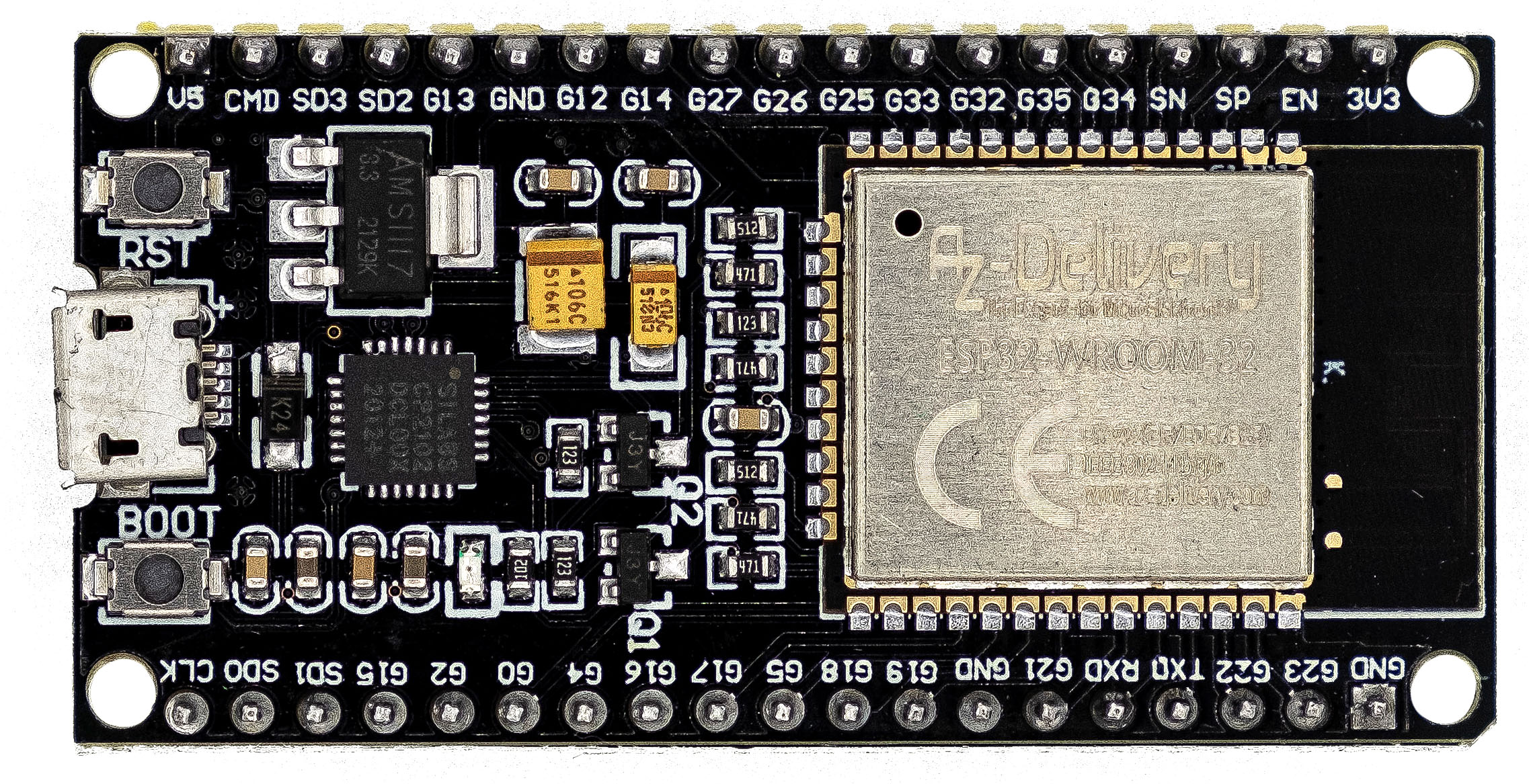
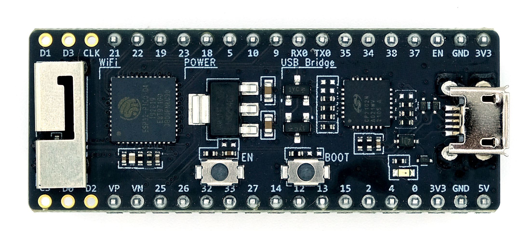
There are various ESP32 boards. Most are based on the ESP32-WROOM-32. Very popular are the development boards like the model shown above left. However, it has a width that is not ideal for breadboards because you only have space left on one side for jumper cables (see below). If you place two breadboards next to each other, the modules will not be wide enough to bridge the +/- bars. This may be a luxury problem, but it’s annoying. As a solution, I recommend multi-breadboards that have only one +/- bar between each board.

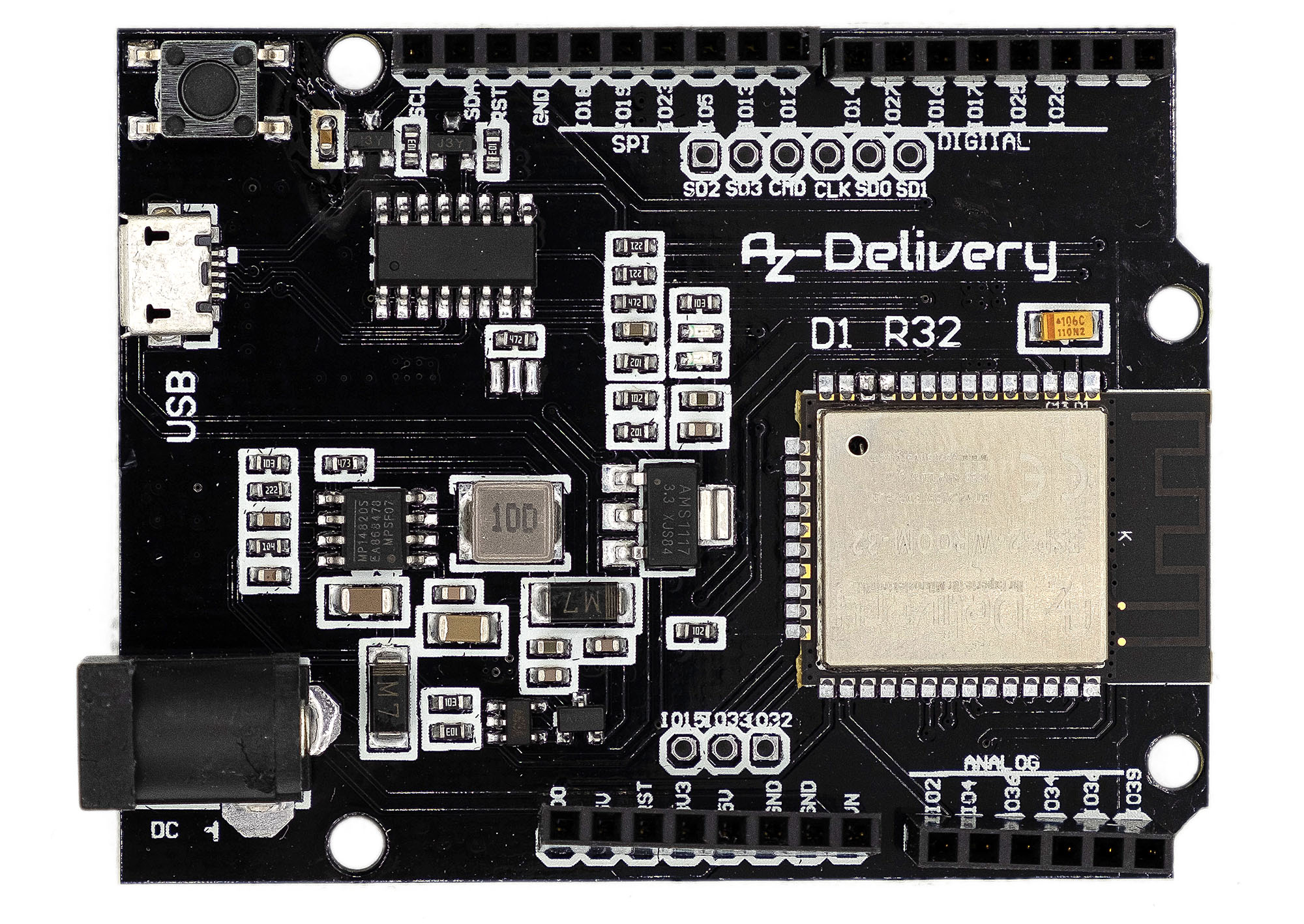
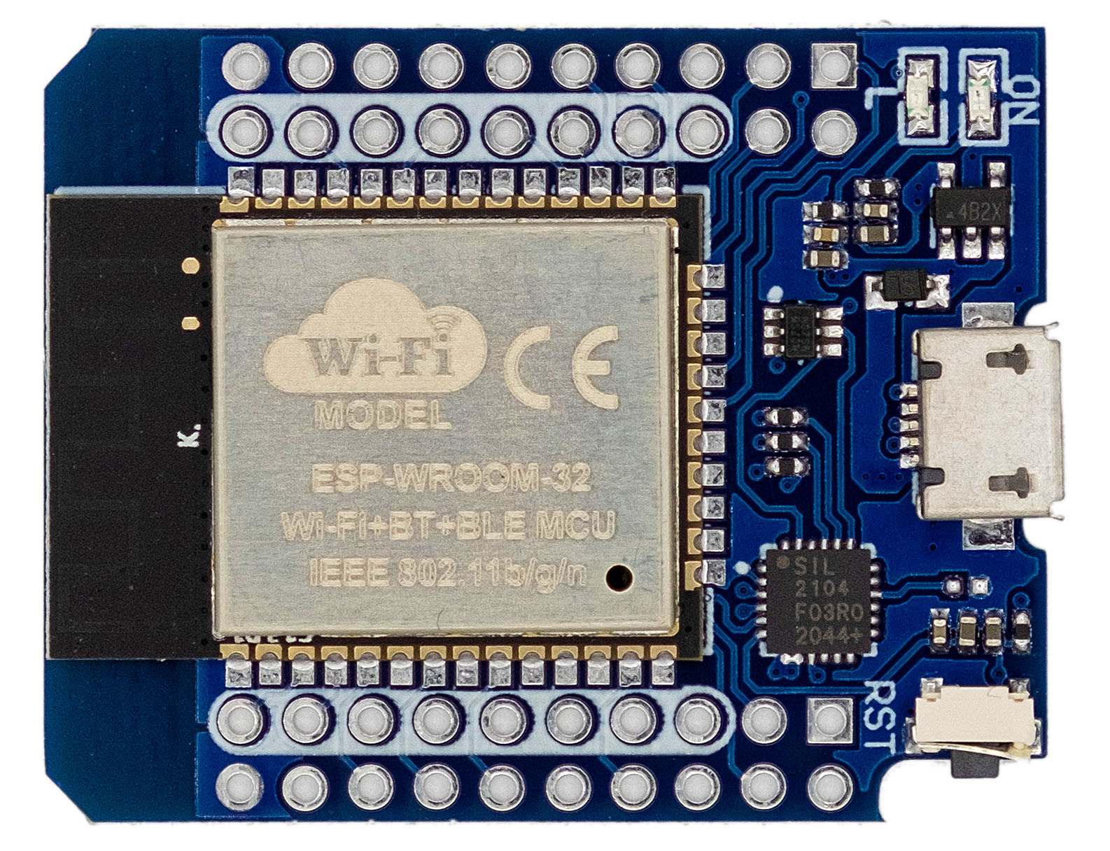
Alternatively, you can also use the “Arduino UNO-like” D1 R32 board. Or you can take an ESP32 Pico because it is a bit smaller.
Features of the ESP32-WROOM-32
The performance of the ESP32 boards makes AVR-based Arduinos like the UNO look old. The four to twelve times higher clock rate and a comparatively huge flash memory are another dimension. A clear advantage for the Arduino (AVR) boards, however, is that the underlying microcontrollers can be easily operated standalone. This allows space and energy saving projects to be realized. Wiring a bare ESP32, on the other hand, is not necessarily what most people like.
Here is an overview of the most important data of the ESP32-WROOM-32:
- Operating voltage: 3.3 volts
- Power consumption: 1μA (hibernation) to max ~240 mA
- the power consumption depends on the mode and the activated components
- in normal operation without WiFi and Bluetooth: approx. 50-70 mA
- Clock rate up to 240 MHz
- 520 kByte internal SRAM (for data and commands)
- External flash memory up to 16 MByte
- most modules have 4 MByte memory, of which about 1 MByte “for free use”
- 34 inputs/outputs:
- usable: 22 GPIOs, 4 GPIs (input only)
- some have certain limitations
- 2 I2C interfaces
- 2 usable SPI interfaces
- 3 UART interfaces
- Real time clock
- 10 touch sensors
- Integrated Hall sensor
- 16 PWM channels
- 2 “real” analog outputs
- Up to 18 analog inputs
- WiFi: 802.11 b/g/n 2.4 GHz
- Bluetooth: 4.2 / BLE (Bluetooth Low Energy)
Integration of the ESP32 into the Arduino IDE
How to make the Arduino IDE ESP32-capable has been described endlessly. Therefore, I will be brief.
- In the Arduino IDE, go to File – > Preferences.
- There you click on the small icon behind “Additional Boards Manager URLs”.
- Enter “https://dl.espressif.com/dl/package_esp32_index.json” as a separate line (without quotation marks).
- Go to Tools – > Board – > Boards Manager.
- Search for “esp32” and install “esp32 by Espressif Systems”.
- You may need to restart the Arduino IDE.
After installation you will find several dozen ESP32 boards to choose from. You have to see which one fits. The “ESP32 Dev Module” is widely used.
Pinout of the ESP32 Development Board
There are different versions of ESP32-WROOM-32 based boards. This means that the pins on your board may be arranged differently, and some pins may also be missing. But what always matches is the multiple function of the pins. This means, for example, that GPIO4 is always HSPI_HD, ADC2_CH0, TOUCH_0 and RTC_IO 10.

“Forbidden” / Restricted Pins
Some pins have certain restrictions, others should be left unconnected. The latter group includes the pins GPIO6 to GPIO11. They are used internally for SPI communication with the flash memory. That is why I have marked them in grey. Just ignore them.
While the ESP32 boots, some of its pins send PWM signals or go into HIGH state for short time. Depending on what you attach to the pins, this can interfere, but it does not have to. These are the pins GPIO0, GPIO1, GPIO3, GPIO5, GPIO14 and GPIO15.
GPIO0, GPIO2, GPIO4, GPIO5, GPIO12 and GPIO15 are so-called “strapping pins” that bring the ESP32 into bootloader or flash mode while booting. If you connect something to it during boot which pull the pins into the HIGH or LOW state, this can lead to unexpected behavior. You may know this from the GPIO0 pin of the ESP8266 ESP-01.
The ADC2_CHx pins cannot be used as analog inputs when WiFi is active.
Digital inputs/outputs of the ESP32
Using the GPIOs as digital inputs and outputs works essentially the same as with the Arduino with the functions pinMode() , digitalWrite() and digitalRead(). If you normally work with Arduino (AVR) boards, you have to get used to the lower voltage of 3.3 volts. The maximum current should not exceed 12 mA.
There is an important difference to the Arduino in the operation of the GPIOs as an input. To achieve a LOW level at a pin when using pinMode(pin, INPUT), you must use an external pull-down resistor with the Arduino. With the ESP32, however, you can connect an internal pull-down resistor via INPUT_PULLDOWN. If you just choose INPUT, then the pin level is undefined.
The pins GPIO34-39 are pure inputs, which is why the name GPI is more appropriate. In addition, there is no internal pull-up or pull-down resistor available on these pins.
Analog inputs/outputs of the ESP32
Analog inputs
The ESP32 has two A/D converters with a resolution of 12 bits. The ADC1 and ADC2 inputs each share one A/D converter. With analogRead(pin) you read the measured values like with the Arduino. The voltage U is (theoretically):
![\[ U\;\text{[V]} = \frac{3.3 \cdot \text{analogRead()}}{4096} \]](https://wolles-elektronikkiste.de/wp-content/ql-cache/quicklatex.com-0cb85d05dca5b0189ddde7c120cbac41_l3.png "Rendered by QuickLaTeX.com")
As excellent as the ESP32’s performance is otherwise, the A/D converters definitely are not:
- The scatter of the measured values is very high.
- Even worse, the results are not linear.
The scatter is something you can get under control. Espressif recommends (here) connecting a 0.1 µF capacitor to the input and averaging the readings. Without a capacitor, I had to average 500 – 1000 readings to get the variation below 0.01 volts.
The non-linearity is a bigger problem. I have checked this out and my findings are consistent with what I have found in other articles:

Some people recommend using “look-up” tables to compensate for the error (e.g. here on GitHub), others recommend regression polynomials (e.g. here). If you need accurate readings, I recommend using a reasonable external A/D converter like the ADS1115.
Analog outputs
analogWrite()
The analogWrite() function is available at all output pins. As you are used to with the Arduino, values between 0 and 255 are available. The underlying PWM frequency is 1 kHz.
The dacWrite function
In addition to analogWrite(), you can use dacWrite() on the ESP32. It provides a true analog signal between 0 and 3.3 volts, which can be output at the two DAC pins. To call the function:
dacWrite(pin, value) with pin = 25 or 26 and value = 0, 1, 2 …. 255.
Theoretically, the voltage U is:
![\[ U\;\text{[V]}=\frac{3.3}{255}\cdot value \]](https://wolles-elektronikkiste.de/wp-content/ql-cache/quicklatex.com-39d6d09d0fe7d789cb7d4901d66b83be_l3.png "Rendered by QuickLaTeX.com")
Practically, it looks like this:

The minimum value in my measurements was 0.086 volts, the maximum value was 3.18 volts. After all, the slope is largely linear, so you can apply a calibration line.
Pulse Width Modulation (PWM)
A detailed introduction to pulse width modulation (PWM) would go beyond the scope of this article. In a nutshell: PWM is used, among other things, to control servo motors or to dim LEDs. A PWM signal is a square wave signal with a defined frequency (= 1/period) and a defined duty cycle. Here is an example of a signal with 25% duty cycle:

The ESP32 has 16 PWM channels that can be assigned to the GPIO pins. However, the inputs GPI32 – GPI39 cannot be used for PWM. The basic setting of the PWM signal is applied with edcAttach(pin, freq, res). pin is the GPIO-Pin, freq is the frequency and res is the resolution in bit. Alternatively, you set the channel yourself with ledcAttachChannel(pin, freq, res, channel).
You start the signal output and set the duty cycle with ledcWrite(pin, dutyCycle). The duty cycle in percent is dutyCycle/2res x 100.
Here is a small example sketch that periodically dims and lights up an LED attached to GPIO18.
const int pwmPin = 18;  // = GPIO18
const int freq = 1000;
const int pwmChannel = 0; // choose 0 - 15
const int res = 8; // 2^8 = 256

void setup(){
  ledcAttach(pwmPin, freq, res); // channel is chosen automatically
  // ledcAttachChannel(pwmPin, freq, res, pwmChannel); // choose channel youself
}

void loop(){
  for(int dutyCycle = 0; dutyCycle <= 256; dutyCycle++){
    ledcWrite(pwmPin, dutyCycle);
    delay(3);
  }
  for(int dutyCycle = 256; dutyCycle >= 0; dutyCycle--){
    ledcWrite(pwmPin, dutyCycle);
    delay(3);
  }
}
Now I briefly come back to the analogWrite() function. When using an Arduino, analogWrite() generates a PWM signal of 490 Hz and a resolution of 8 bits on most pins (see here on the Arduino pages). With ledcAttach(pin, 490, 8), you can easily do the same.
Maximum PWM resolution and frequency
You can select values between 1 and 15 bits as resolution. The resolution and the internal timer frequency (80 MHz) determine the maximum frequency of the PWM signal:
![\[ f_{\text{max}}=\frac{80000000}{2^\text{(res in bit)}} \;\;\;\;\;\;\text{z.B.:}\;\; \text{res} = 10\;\text{Bit}\;\;\; =>\;\;\;f_{\text{max}}=\frac{80000000}{2^{10}}= 78125\; \text{[Hz]} \]](https://wolles-elektronikkiste.de/wp-content/ql-cache/quicklatex.com-622d38fcdb10280401ecfbb0efc30c28_l3.png "Rendered by QuickLaTeX.com")
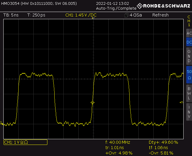
As an extreme example, you choose a resolution of one bit. This sets the duty cycle to 50% and the maximum frequency is 40 MHz. In this range, my oscilloscope is at its limit and therefore the signal is not very sharp.
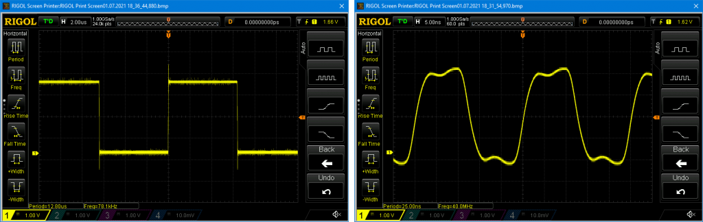
A friendly reader (thanks to Stefan Groß), has measured the signal with his more professional equipment (active probe, 1 GHz, 10:1):
Using the I2C interfaces of the ESP32
In contrast to the Arduino (UNO), the ESP32 has two I2C interfaces. The standard interface is assigned to GPIO21 and GPIO22. If you use the default, the operation is the same as with the Arduino. This means that you include the Wire.h library and use its functions as usual.
But you have to keep in mind that the ESP32 voltage is 3.3 volts. If you connect a 5 volt device via I2C, you should apply a level shifter or voltage divider. Of course, this also applies to SPI and UART. The pins are not tolerant to 5 volts.
Another difference is that you can assign the I2C interface to other GPIOs. How to do this, how to use the second I2C interface and how to pass the corresponding TwoWire objects to other objects, I have described here in great detail. That is why I will not go into it in more detail.
Using the SPI interfaces of the ESP32
The ESP32 has a total of four SPI interfaces. However, only two of them are available to you, namely VSPI and HSPI. The other two SPI interfaces are used internally. VSPI is the default SPI interface. It is assigned to the GPIOs 18 (VSPI_CLK), 19 (VSPI_MISO), 23 (VSPI_MOSI) and 5 (VSPI_CS = Chip Select). If you use VSPI, it is very similar to the Arduino. You include SPI.h and use functions of this class as usual. Although the interface is called VSPI, the object is called SPI.
If you want to use HSPI, then you first have to create the corresponding SPI object. Here is a simple little example. I attached two MPU9250 modules to HSPI and VSPI. I used Bolderflight’s MPU9250 library which can be found here on GitHub. But you don’t really have to deal with it. Just look at the first lines since they show the principle.
#include "MPU9250.h"
#include "SPI.h"

SPIClass SPI_2(HSPI); // create SPI_2 object
MPU9250 IMU_1(SPI,5);  // pass standard SPI object (VSPI) and Chip Select
MPU9250 IMU_2(SPI_2,15);  // pass SPI_2 object (HSPI) and Chip Select

int status;

void setup() {
  Serial.begin(115200);

  status = IMU_1.begin();
  if (status < 0) {
    Serial.println("IMU 1 initialization unsuccessful");
    while(1) {}
  }
  status = IMU_2.begin();
  if (status < 0) {
    Serial.println("IMU 2 initialization unsuccessful");
    while(1) {}
  }
}

void loop() {
  IMU_1.readSensor();
  Serial.println("IMU 1 Acceleration Data:");
  Serial.print(IMU_1.getAccelX_mss(),6);
  Serial.print("\t");
  Serial.print(IMU_1.getAccelY_mss(),6);
  Serial.print("\t");
  Serial.println(IMU_1.getAccelZ_mss(),6);

  IMU_2.readSensor();
  Serial.println("IMU 2 Acceleration Data:");
  Serial.print(IMU_2.getAccelX_mss(),6);
  Serial.print("\t");
  Serial.print(IMU_2.getAccelY_mss(),6);
  Serial.print("\t");
  Serial.println(IMU_2.getAccelZ_mss(),6);

  delay(1000);
}
Changing the default SPI pins
You can also assign VSPI and HSPI to other pins. A detailed sketch can be found here on GitHub.
Using the UART (Serial) interface with the ESP32
The ESP32 has three serial interfaces called U0UXD, U1UXD and U2UXD. The three interfaces are assigned to the following pins:

U0UXD is the default serial interface. It is used, among other things, for output to the serial monitor. It is initialized with Serial.begin(baud rate) as usual. If you want to use U1UXD and U2UXD, then you determine its properties with Serialx.begin(baud rate, protocol, RXPin, TXPin) (with x = 1 or 2). If you call the begin function only with the baud rate parameter, the default settings apply.
Very theoretical, but with the example, it should become clear:
#define RX1 16
#define TX1 17
#define RX2 12
#define TX2 13

void setup() {
  Serial.begin(115200);
  Serial1.begin(115200, SERIAL_8N1, RX1, TX1);
  Serial2.begin(115200, SERIAL_8N1, RX2, TX2);
  delay(100);
  if(Serial1){
    Serial.println("Serial1 successfully set up");
  }
  if(Serial2){
    Serial.println("Serial2 successfully set up");
  }
}

void loop(){}
SERIAL_8N1 means: 8 bits, no parity (N = no), 1 stop bit. That’s the standard. I found a collection of possible protocol parameters here on GitHub.
You can also change the pins for the default interface using the same function: Serial.begin(baud rate, protocoll, RXPin, TXPin).
Touch Pins
The touch pins of the ESP32 are capacitance sensitive. The larger the capacitance, the smaller the measured value. Since the human body has also a capacitance, the pins react to touch. The small example sketch shows how it works:
void setup() {
  Serial.begin(9600);
  while(!Serial){}
  Serial.println("ESP32 Touch Test");
}

void loop() {
  Serial.println(touchRead(4));  // get value of Touch 0 pin = GPIO 4
  //Serial.println(touchRead(T0)); // alternative
  delay(1000);
}
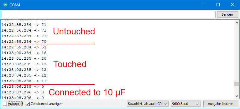
I connected the touch pin to a jumper cable and left the loose end of the cable untouched at first, then touched it and then connected it to a 10 μF capacitor. This is what the output looked like:
Hall Sensor
In case you have read somewhere about the hall sensor function hallRead() somewhere: It is no longer supported. The hall sensor wasn’t particularly good, but support didn’t necessarily have to be removed.
Interrupts
As for the interrupt programming of the ESP32, I could fill an entire article. Therefore I will only deal with external GPIO interrupts.
You can set up interrupts on any GPIO pin, including the input pins GPI34 – GPI39. The handling is the similar to the Arduino boards, except for one special feature. If you use the attribute IRAM_ATTR in the Interrupt Service Routine (ISR), the code is not stored in flash memory, but in RAM. This makes the execution much faster. You have to place the ISR function before setup() (at least that’s how it is in the Arduino IDE). It may sound complicated, but it’s not.
In my short example, a push of a button provides a HIGH signal to GPIO4. This triggers the interrupt. First, the highly complex 😉 circuit:
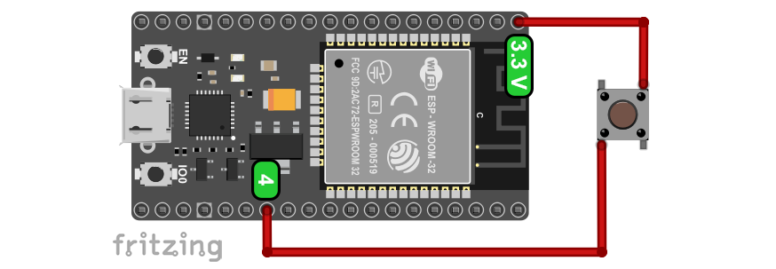
Here’s the sketch:
int interruptPin = 4; // define GPIO4 as interrupt pin
volatile bool event = false;

void IRAM_ATTR eventISR(){
  event = true;
  detachInterrupt(interruptPin);
}

void setup() {
  Serial.begin(115200);
  while(!Serial){}
  pinMode(interruptPin, INPUT_PULLDOWN);
  attachInterrupt(interruptPin, eventISR, RISING);
}

void loop() {
  if(event){
    Serial.println("Interrupt!");
    delay(1000); //debouncing
    event = false;
    attachInterrupt(interruptPin, eventISR, RISING);
  }
}
You can also easily define multiple interrupts. Would be a nice exercise for you, wouldn’t it?
Saving Power – Sleep Modes
The ESP32 is as powerful as it is power hungry. This can be a problem with battery-powered projects. However, there are ways to reduce power consumption to a fraction. First, you can turn off certain components. The biggest power consumers are WiFi and Bluetooth. If you use them, you should turn them off in between if possible. For this purpose, you can use WiFi.mode(WIFI_OFF) and btStop(). In addition, there are different sleep modes you can choose from.
I want to limit the length of this article, so I will only briefly discuss light sleep and deep sleep. With esp_sleep_enable_timer_wakeup() you define a sleep phase, after which the ESP32 wakes up again. As parameter, you pass the time in microseconds. But only when you call esp_deep_sleep_start() or esp_light_sleep_start(), the sleep phase begins.
After light sleep, the program continues where it stopped. After deep sleep, it restarts. You can try this out with the following sketch:
const int unsigned long microSecToSec = 1000000;
const int sleepTime = 5;

void setup(){
  Serial.begin(115200);
  while(!Serial){}

  esp_sleep_enable_timer_wakeup(sleepTime * microSecToSec);
  Serial.println();
  Serial.println("ESP32 will go to sleep for 5 seconds....");
  delay(2000);
  Serial.println("...now");
  esp_deep_sleep_start();
  //esp_light_sleep_start();
  Serial.println("This message will only be printed after light sleep");
}

void loop(){
}
Wake up via external signal
You can also wake up the ESP32 via external signals on one of the RTC_IO pins. You set that up with esp_sleep_enable_ext0_wakeup(GPIO_NUM_x, HIGH/LOW). The function expects the pin number in the format “GPIO_NUM_x” as the first argument. If you pass an integer instead, there will be an error message. The second parameter determines whether the wake-up signal is a HIGH or a LOW.
void setup(){
  Serial.begin(115200);
  while(!Serial){};
  pinMode(GPIO_NUM_4, INPUT_PULLDOWN);
  Serial.println();
  esp_sleep_enable_ext0_wakeup(GPIO_NUM_4,1);
  Serial.println("ESP32 will go to deep sleep...");
  delay(1000);
  Serial.println("...now");
  esp_deep_sleep_start(); //
  Serial.println("This message will only be printed after light sleep");
}

void loop(){
}
Waking up with Touch
You control waking up by touch with the esp_sleep_enable_touchpad_wakeup() function. Before that, however, you have to set up a touch interrupt. Here’s how:
#define THRESHOLD 40
void callback(){}

void setup(){
  Serial.begin(115200);
  delay(1000);
  touchAttachInterrupt(T4, callback, THRESHOLD); //T4 = GPIO13
  esp_sleep_enable_touchpad_wakeup();
  Serial.println("Going to deep sleep...");
  delay(1000);
  Serial.println("...now");
  esp_deep_sleep_start();
}

void loop(){
}
So, all you have to do is touch the GPIO13 (easiest via a jumper cable) and the ESP32 will wake up. If you want, you can add further commands to callback(){}. Of course, the touch interrupt also works without an alarm function.
WiFi
The use of WiFi is a quite complex topic. Therefore, I have covered this in a separate article. You find it here.
Bluetooth
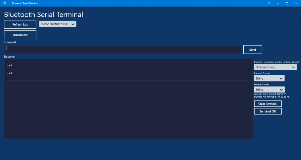
The topic of Bluetooth is also very extensive. I will show a simple example of how to switch LEDs connected to the ESP32 via smartphone or computer. To do this, you first need a Bluetooth terminal program. For the PC I suggest Bluetooth Serial Terminal, for Android smartphones I suggest Bluetooth Terminal.
On the ESP32 side, connect two LEDs on GPIO4 and GPIO13. Of course, you can also choose other pins and expand the example as you like.
Upload the following sketch, then pair the ESP32 with your smartphone or PC. The ESP32 appears under the name you give with espBT.begin("name"). After pairing, you still have to connect the ESP32 in the computer program or in the smartphone app. In the app you click on the three dots, in the PC program it is obvious what to do.
If, for example, you send “+4” to the ESP32, you switch on the LED at GPIO4. With “-4”, on the other hand, you switch it off.
#include "BluetoothSerial.h"

BluetoothSerial espBT;

void setup() {
  Serial.begin(115200);
  pinMode(4, OUTPUT);
  pinMode(13, OUTPUT);
  espBT.begin("ESP32 Bluetooth Example");
  Serial.println("Pair your BT device now");
}

void loop(){
  if(espBT.available()){
    char command = espBT.read();
    int state = LOW;
    int pin = espBT.parseInt();
    Serial.print("Received: ");
    Serial.print(command);
    Serial.println(pin);

    if((command == '+')||(command == '-')){
      if(command == '+'){
        state = HIGH;
      }
      else state = LOW;
      digitalWrite(pin, state);
    }

    espBT.print("Received: ");
    espBT.print(command);
    espBT.println(pin);
  }
}
And this is what the Bluetooth Serial Terminal looks like:
A few more brief explanations:
BluetoothSerial espBTcreates the Bluetooth object.espBT.read()reads the first character, i.e. “+” or “–”.espBT.parseInt()identifies the next sequence of digits in the incoming characters and reads them as an integer (very useful function).
Everything else you should be able to understand. If not, then there is a more detailed tutorial here, for example.
Fash hungry BluetoothSerial – enlarging the flash
After including BluetoothSerial.h, you will see that the remaining flash memory has significantly decreased. If you want to increase the flash, go to Tools → Partition Scheme and select the setting “HugeAPP (3MB NoOTA/1 MB SPIFFS)”.
“Exotic” pin functions
If you go back to the pinout diagram from the beginning, you will see that I have explained most of the pin functions. However, a few are still missing. Most people will probably never use them.
- SENS_VP / SENS_VN: Input for small DC signals, e.g. thermocouples. The pins are also used internally for the Hall sensor.
- VDET1 / VDT2: “they belong to the RTC power domain, which means that the devices that fall under the RTC can control them. It means e.g. that they can be used as ADC pins and that the ULP coprocessor can read them. ” – no idea what that really means, but exactly this wording is quoted quite often.
- xSPI_WP / xSPI_HD: required to control 4-bit SPI transactions; WP = Write Protection, HD = Hold.
- XTAL_P/ XTAL_N: external oscillator input for the ULP (Ultra Low Power) processor.
The APIs (Application Programming Interfaces)
As you have seen, there are some functions such as ledcAttach() that you will not recognize from the standard repertoire of Arduino functions. These belong to the ESP32 APIs, that you can find here. It is well worth taking a look.
Acknowledgement
I have found the cloud in the post image at Clker free vector images on Pixabay.