About this post
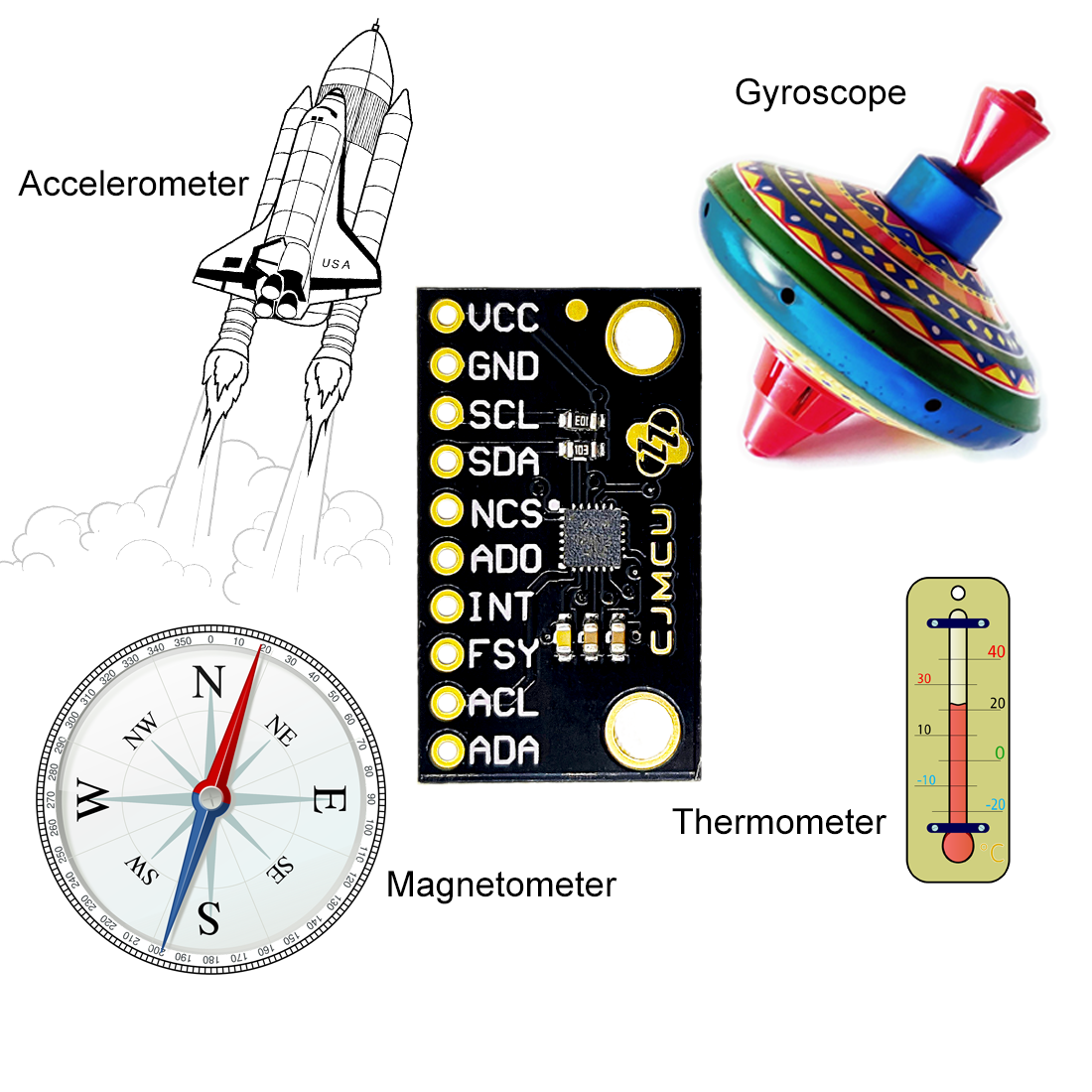
This is the continuation of the first part of my post about the 9-axis sensor ICM-20948. In the first part, I first discussed the technical characteristics. Then I started to introduce my library ICM20948_WE. You can download it here from GitHub or install it via the library manager of the Arduino IDE.
I had shown you how to retrieve data from the accelerometer, gyroscope, magnetometer and thermometer and how to use the calibration functions. In addition, I have introduced functions for measuring tilt angles.
This part deals with the following topics:
- Cycle mode
- Interrupts
- FIFO buffer
As in the first part, I present the functions of my library using example sketches.
ICM20948_08_cycle.ino
In cycle mode, the sensors sleep between measurements. This saves you valuable energy in battery-powered projects. For the following example sketch I have measured a power consumption of 2.3 mA. With the cycle mode deactivated, the current consumption was 4.4 mA.
You activate the cycle mode with enableCycle(parameter). The parameter (see sketch) defines which sensors should go into cycle mode.
#include <Wire.h>
#include <ICM20948_WE.h>
#define ICM20948_ADDR 0x68

/* There are several ways to create your ICM20948 object:
 * ICM20948_WE myIMU = ICM20948_WE()              -> uses Wire / I2C Address = 0x68
 * ICM20948_WE myIMU = ICM20948_WE(ICM20948_ADDR) -> uses Wire / ICM20948_ADDR
 * ICM20948_WE myIMU = ICM20948_WE(&wire2)        -> uses the TwoWire object wire2 / ICM20948_ADDR
 * ICM20948_WE myIMU = ICM20948_WE(&wire2, ICM20948_ADDR) -> all together
 * ICM20948_WE myIMU = ICM20948_WE(CS_PIN, spi);  -> uses SPI, spi is just a flag, see SPI example
 * ICM20948_WE myIMU = ICM20948_WE(&SPI, CS_PIN, spi);  -> uses SPI / passes the SPI object, spi is just a flag, see SPI example
 */
ICM20948_WE myIMU = ICM20948_WE(ICM20948_ADDR);

void setup() {
  //delay(2000); // maybe needed for some MCUs, in particular for startup after power off
  Wire.begin();
  Serial.begin(115200);
  while(!Serial) {}

  if(!myIMU.init()){
    Serial.println("ICM20948 does not respond");
  }
  else{
    Serial.println("ICM20948 is connected");
  }

  if (!myIMU.initMagnetometer()) {
    Serial.println("Magnetometer does not respond");
  }
  else {
    Serial.println("Magnetometer is connected");
  }

  /*  This is a method to calibrate. You have to determine the minimum and maximum
   *  raw acceleration values of the axes determined in the range +/- 2 g.
   *  You call the function as follows: setAccOffsets(xMin,xMax,yMin,yMax,zMin,zMax);
   *  The parameters are floats.
   *  The calibration changes the slope / ratio of raw acceleration vs g. The zero point is
   *  set as (min + max)/2.
   */
//  myIMU.setAccOffsets(-16330.0, 16450.0, -16600.0, 16180.0, -16640.0, 16560.0);

  /*  The starting point, if you position the ICM20948 flat, is not necessarily 0g/0g/1g for x/y/z.
   *  The autoOffset function measures offset. It assumes your ICM20948 is positioned flat with its
   *  x,y-plane. The more you deviate from this, the less accurate will be your results.
   *  It overwrites the zero points of setAccOffsets, but keeps the correction of the slope.
   *  The function also measures the offset of the gyroscope data. The gyroscope offset does not
   *  depend on the positioning.
   *  This function needs to be called after setAccOffsets but before other settings since it will
   *  overwrite settings!
   *  You can query the offsets with the functions:
   *  xyzFloat getAccOffsets() and xyzFloat getGyrOffsets()
   *  You can apply the offsets using:
   *  setAccOffsets(xyzFloat yourOffsets) and setGyrOffsets(xyzFloat yourOffsets)
   */
//  Serial.println("Position your ICM20948 flat and don't move it - calibrating...");
//  delay(1000);
//  myIMU.autoOffsets();
//  Serial.println("Done!");

  /*  The gyroscope data is not zero, even if you don't move the ICM20948.
   *  To start at zero, you can apply offset values. These are the gyroscope raw values you obtain
   *  using the +/- 250 degrees/s range.
   *  Use either autoOffset or setGyrOffsets, not both.
   */
//  myIMU.setGyrOffsets(-115.0, 130.0, 105.0);


  /* enables or disables the acceleration sensor, default: enabled */
  //myIMU.enableAcc(false);

  /*  ICM20948_ACC_RANGE_2G      2 g   (default)
   *  ICM20948_ACC_RANGE_4G      4 g
   *  ICM20948_ACC_RANGE_8G      8 g
   *  ICM20948_ACC_RANGE_16G    16 g
   */
  myIMU.setAccRange(ICM20948_ACC_RANGE_2G);

  /*  Choose a level for the Digital Low Pass Filter or switch it off.
   *  ICM20948_DLPF_0, ICM20948_DLPF_2, ...... ICM20948_DLPF_7, ICM20948_DLPF_OFF
   *
   *  IMPORTANT: This needs to be ICM20948_DLPF_7 if DLPF is used in cycle mode!
   *
   *  DLPF       3dB Bandwidth [Hz]      Output Rate [Hz]
   *    0              246.0               1125/(1+ASRD)
   *    1              246.0               1125/(1+ASRD)
   *    2              111.4               1125/(1+ASRD)
   *    3               50.4               1125/(1+ASRD)
   *    4               23.9               1125/(1+ASRD)
   *    5               11.5               1125/(1+ASRD)
   *    6                5.7               1125/(1+ASRD)
   *    7              473.0               1125/(1+ASRD)
   *    OFF           1209.0               4500
   *
   *    ASRD = Accelerometer Sample Rate Divider (0...4095)
   *    You achieve lowest noise using level 6
   */
  myIMU.setAccDLPF(ICM20948_DLPF_7);

  /*  Acceleration sample rate divider divides the output rate of the accelerometer.
   *  Sample rate = Basic sample rate / (1 + divider)
   *  It can only be applied if the corresponding DLPF is not off!
   *  Divider is a number 0...4095 (different range compared to gyroscope)
   *  If sample rates are set for the accelerometer and the gyroscope, the gyroscope
   *  sample rate has priority.
   */
  myIMU.setAccSampleRateDivider(2048);

  /* enables or disables the gyroscope sensor, default: enabled */
  //myIMU.enableGyr(false);

  /*  ICM20948_GYRO_RANGE_250       250 degrees per second (default)
   *  ICM20948_GYRO_RANGE_500       500 degrees per second
   *  ICM20948_GYRO_RANGE_1000     1000 degrees per second
   *  ICM20948_GYRO_RANGE_2000     2000 degrees per second
   */
 // myIMU.setGyrRange(ICM20948_GYRO_RANGE_250);

  /*  Choose a level for the Digital Low Pass Filter or switch it off.
   *  ICM20948_DLPF_0, ICM20948_DLPF_2, ...... ICM20948_DLPF_7, ICM20948_DLPF_OFF
   *
   *  DLPF       3dB Bandwidth [Hz]      Output Rate [Hz]
   *    0              196.6               1125/(1+GSRD)
   *    1              151.8               1125/(1+GSRD)
   *    2              119.5               1125/(1+GSRD)
   *    3               51.2               1125/(1+GSRD)
   *    4               23.9               1125/(1+GSRD)
   *    5               11.6               1125/(1+GSRD)
   *    6                5.7               1125/(1+GSRD)
   *    7              361.4               1125/(1+GSRD)
   *    OFF          12106.0               9000
   *
   *    GSRD = Gyroscope Sample Rate Divider (0...255)
   *    You achieve lowest noise using level 6
   */
  myIMU.setGyrDLPF(ICM20948_DLPF_6);

  /*  Gyroscope sample rate divider divides the output rate of the gyroscope.
   *  Sample rate = Basic sample rate / (1 + divider)
   *  It can only be applied if the corresponding DLPF is not OFF!
   *  Divider is a number 0...255
   *  If sample rates are set for the accelerometer and the gyroscope, the gyroscope
   *  sample rate has priority.
   */
  myIMU.setGyrSampleRateDivider(255);

  /* In cycle mode the sensors wake up in the frequency of sample rate. You can define
   * which sensors shall work in cycle mode.
   *
   *  ICM20948_NO_CYCLE
   *  ICM20948_GYR_CYCLE
   *  ICM20948_ACC_CYCLE
   *  ICM20948_ACC_GYR_CYCLE
   *  ICM20948_ACC_GYR_I2C_MST_CYCLE
   */
  myIMU.enableCycle(ICM20948_ACC_GYR_I2C_MST_CYCLE);

  /* The Low Power Mode does not work if DLPF is enabled */
  //myIMU.enableLowPower(true);

  /* In cycle mode you need to set the number of measured values for the gyroscope
   * to be averaged. You can select 1,2,4,8,16,32,64 or 128:
   * ICM20948_GYR_AVG_1, ICM20948_GYR_AVG_2, ..... , ICM20948_GYR_AVG_128
   * The on-time for measurements increases with the number of samples to be averaged:
   * 1 -> 1.15 ms, 2 -> 1.59 ms, .... , 128 -> 57.59 ms (see data sheet)
   */
  myIMU.setGyrAverageInCycleMode(ICM20948_GYR_AVG_1);

  /* In cycle mode you need to set the number of measured values for the accelerometer
   * to be averaged. You can select 4,8,16,32:
   * ICM20948_ACC_AVG_4, ICM20948_ACC_AVG_8, ICM20948_ACC_AVG_16, ICM20948_ACC_AVG_32
   * The on-time for measurements increases with the number of samples to be averaged:
   * 4 -> 1.488 ms, 8 -> 2.377 ms, 16 -> 4.154 ms , 32 -> 7.71 ms (see data sheet)
   * If DLPF is OFF, then with ICM20948_ACC_AVG_4 only one sample is taken!
   */
  myIMU.setAccAverageInCycleMode(ICM20948_ACC_AVG_4);

  /* setI2CMstSampleRate sets the rate of the devices controlled by the I2C master,
   * i.e. the magnetometer. It is not the internal sample rate of the magnetometer, but
   * the output rate of the I2C master. Allowed values are x = 0...15. The sample rate is
   * 1.1 kHz / (2^x). Example: x = 13 => Sample rate = 1.1 kHz / 8192 = ~0.1343 Hz,
   * or: data output every ~7.45 seconds.
   */
  myIMU.setI2CMstSampleRate(13);
}

void loop() {
  xyzFloat gValue;
  xyzFloat gyrValue;
  xyzFloat magValue;
  myIMU.readSensor();
  myIMU.getGValues(&gValue);
  myIMU.getGyrValues(&gyrValue);
  myIMU.getMagValues(&magValue);

  Serial.println("g-values (x,y,z):");
  Serial.print(gValue.x);
  Serial.print("   ");
  Serial.print(gValue.y);
  Serial.print("   ");
  Serial.println(gValue.z);

  Serial.println("Gyroscope (x,y,z):");
  Serial.print(gyrValue.x);
  Serial.print("   ");
  Serial.print(gyrValue.y);
  Serial.print("   ");
  Serial.println(gyrValue.z);

  Serial.println("Magnetometer Data in µTesla: ");
  Serial.print(magValue.x);
  Serial.print("   ");
  Serial.print(magValue.y);
  Serial.print("   ");
  Serial.println(magValue.z);

  Serial.println();

  delay(500);
}
setAccAverageInCycleMode() and setGyrAverageInCycleMode() determine the number of individual measurements from which the result is averaged. However, you have to keep in mind that too many individual measurements dilute the energy-saving effect.
There are still a few points to consider:
- When DLPF is activated, the accelerometer measures incorrect values in cycle mode.
- According to the data sheet, the sample rate divider of the accelerometer should not work when DLPF is switched off – but it does!
- In addition to the cycle mode, you can (de-)activate a low-power mode using
enableLowPower(true/false). This resulted in a further 0.2 mA savings in the sketch above. The function only has an effect when the cycle mode is active. I did not find out what the energy-saving mode does exactly, except save power. setI2CSampleMasterRate(x)determines the frequency with which the measured values of the sensors addressed via the I2C auxiliary interface are queried. The frequency is 1100/2x kHz (0.134 Hz in the example sketch). This function also saves you power.
- In my library, it is only relevant for the magnetometer.
Using interrupts of the ICM-20948
I have implemented the following interrupts of the ICM-20948:
- Data ready: triggers when new readings are available.
- Wake-on-motion (“WOM”): triggers when an acceleration value set by you is exceeded.
- FIFO Overflow: triggers when the FIFO buffer is full (512 bytes / 4096 bytes).
- FSYNC: if activated, you choose if it triggers when a HIGH or a LOW level is detected at FSYNC.
ICM20948_09_data_ready_interrupt.ino
In the following sketch, the data ready interrupt controls the output frequency of the measured values. I have enabled the accelerometer only. The sample rate divider is set to 4095 and the DLPF level is 1. This results in an output frequency of 1125 / 4096 = ~0.27 Hz.
#include <Wire.h>
#include <ICM20948_WE.h>
#define ICM20948_ADDR 0x68

/* There are several ways to create your ICM20948 object:
 * ICM20948_WE myIMU = ICM20948_WE()              -> uses Wire / I2C Address = 0x68
 * ICM20948_WE myIMU = ICM20948_WE(ICM20948_ADDR) -> uses Wire / ICM20948_ADDR
 * ICM20948_WE myIMU = ICM20948_WE(&wire2)        -> uses the TwoWire object wire2 / ICM20948_ADDR
 * ICM20948_WE myIMU = ICM20948_WE(&wire2, ICM20948_ADDR) -> all together
 * ICM20948_WE myIMU = ICM20948_WE(CS_PIN, spi);  -> uses SPI, spi is just a flag, see SPI example
 * ICM20948_WE myIMU = ICM20948_WE(&SPI, CS_PIN, spi);  -> uses SPI / passes the SPI object, spi is just a flag, see SPI example
 */
ICM20948_WE myIMU = ICM20948_WE(ICM20948_ADDR);

const int intPin = 2;
volatile bool dataReady = false;

void setup() {
  //delay(2000); // maybe needed for some MCUs, in particular for startup after power off
  Wire.begin();
  Serial.begin(115200);
  while(!Serial) {}

  if(!myIMU.init()){
    Serial.println("ICM20948 does not respond");
  }
  else{
    Serial.println("ICM20948 is connected");
  }

  /*  This is a method to calibrate. You have to determine the minimum and maximum
   *  raw acceleration values of the axes determined in the range +/- 2 g.
   *  You call the function as follows: setAccOffsets(xMin,xMax,yMin,yMax,zMin,zMax);
   *  The parameters are floats.
   *  The calibration changes the slope / ratio of raw acceleration vs g. The zero point is
   *  set as (min + max)/2.
   */
//  myIMU.setAccOffsets(-16330.0, 16450.0, -16600.0, 16180.0, -16520.0, 16690.0);

  /*  The starting point, if you position the ICM20948 flat, is not necessarily 0g/0g/1g for x/y/z.
   *  The autoOffset function measures offset. It assumes your ICM20948 is positioned flat with its
   *  x,y-plane. The more you deviate from this, the less accurate will be your results.
   *  It overwrites the zero points of setAccOffsets, but keeps the correction of the slope.
   *  The function also measures the offset of the gyroscope data. The gyroscope offset does not
   *  depend on the positioning.
   *  This function needs to be called after setAccOffsets but before other settings since it will
   *  overwrite settings!
   *  You can query the offsets with the functions:
   *  xyzFloat getAccOffsets() and xyzFloat getGyrOffsets()
   *  You can apply the offsets using:
   *  setAccOffsets(xyzFloat yourOffsets) and setGyrOffsets(xyzFloat yourOffsets)
   */
//  Serial.println("Position your ICM20948 flat and don't move it - calibrating...");
//  delay(1000);
//  myIMU.autoOffsets();
//  Serial.println("Done!");

  /*  The gyroscope data is not zero, even if you don't move the ICM20948.
   *  To start at zero, you can apply offset values. These are the gyroscope raw values you obtain
   *  using the +/- 250 degrees/s range.
   *  Use either autoOffset or setGyrOffsets, not both.
   */
//  myIMU.setGyrOffsets(-115.0, 130.0, 105.0);


  /* enables or disables the acceleration sensor, default: enabled */
  //myIMU.enableAcc(false);

  /*  ICM20948_ACC_RANGE_2G      2 g   (default)
   *  ICM20948_ACC_RANGE_4G      4 g
   *  ICM20948_ACC_RANGE_8G      8 g
   *  ICM20948_ACC_RANGE_16G    16 g
   */
  myIMU.setAccRange(ICM20948_ACC_RANGE_2G);

  /*  Choose a level for the Digital Low Pass Filter or switch it off.
   *  ICM20948_DLPF_0, ICM20948_DLPF_2, ...... ICM20948_DLPF_7, ICM20948_DLPF_OFF
   *
   *  IMPORTANT: This needs to be ICM20948_DLPF_7 if DLPF is used in cycle mode!
   *
   *  DLPF       3dB Bandwidth [Hz]      Output Rate [Hz]
   *    0              246.0               1125/(1+ASRD)
   *    1              246.0               1125/(1+ASRD)
   *    2              111.4               1125/(1+ASRD)
   *    3               50.4               1125/(1+ASRD)
   *    4               23.9               1125/(1+ASRD)
   *    5               11.5               1125/(1+ASRD)
   *    6                5.7               1125/(1+ASRD)
   *    7              473.0               1125/(1+ASRD)
   *    OFF           1209.0               4500
   *
   *    ASRD = Accelerometer Sample Rate Divider (0...4095)
   *    You achieve lowest noise using level 6
   */
  myIMU.setAccDLPF(ICM20948_DLPF_1);

  /*  Acceleration sample rate divider divides the output rate of the accelerometer.
   *  Sample rate = Basic sample rate / (1 + divider)
   *  It can only be applied if the corresponding DLPF is not off!
   *  Divider is a number 0...4095 (different range compared to gyroscope)
   *  If sample rates are set for the accelerometer and the gyroscope, the gyroscope
   *  sample rate has priority.
   */
  myIMU.setAccSampleRateDivider(4095);

  /* enables or disables the gyroscope sensor, default: enabled */
  myIMU.enableGyr(false);

  /*  ICM20948_GYRO_RANGE_250       250 degrees per second (default)
   *  ICM20948_GYRO_RANGE_500       500 degrees per second
   *  ICM20948_GYRO_RANGE_1000     1000 degrees per second
   *  ICM20948_GYRO_RANGE_2000     2000 degrees per second
   */
 // myIMU.setGyrRange(ICM20948_GYRO_RANGE_250);

  /*  Choose a level for the Digital Low Pass Filter or switch it off.
   *  ICM20948_DLPF_0, ICM20948_DLPF_2, ...... ICM20948_DLPF_7, ICM20948_DLPF_OFF
   *
   *  DLPF       3dB Bandwidth [Hz]      Output Rate [Hz]
   *    0              196.6               1125/(1+GSRD)
   *    1              151.8               1125/(1+GSRD)
   *    2              119.5               1125/(1+GSRD)
   *    3               51.2               1125/(1+GSRD)
   *    4               23.9               1125/(1+GSRD)
   *    5               11.6               1125/(1+GSRD)
   *    6                5.7               1125/(1+GSRD)
   *    7              361.4               1125/(1+GSRD)
   *    OFF          12106.0               9000
   *
   *    GSRD = Gyroscope Sample Rate Divider (0...255)
   *    You achieve lowest noise using level 6
   */
  myIMU.setGyrDLPF(ICM20948_DLPF_1);

  /*  Gyroscope sample rate divider divides the output rate of the gyroscope.
   *  Sample rate = Basic sample rate / (1 + divider)
   *  It can only be applied if the corresponding DLPF is not OFF!
   *  Divider is a number 0...255
   *  If sample rates are set for the accelerometer and the gyroscope, the gyroscope
   *  sample rate has priority.
   */
  myIMU.setGyrSampleRateDivider(255);

  /* Set the interrupt pin:
   * ICM20948_ACT_LOW  = active-low
   * ICM20948_ACT_HIGH = active-high (default)
   */
   //myIMU.setIntPinPolarity(ICM20948_ACT_LOW);

   /*  If latch is enabled the interrupt pin level is held until the interrupt status
   *  is cleared. If latch is disabled the interrupt pulse is ~50µs (default).
   */
   myIMU.enableIntLatch(true);

  /* The interrupts ICM20948_FSYNC_INT, ICM20948_WOM_INT and ICM20948_DMP_INT can be
   * cleared by any read or will only be cleared if the interrupt status register is
   * read (default).
   */
   //myIMU.enableClearIntByAnyRead(true);

  /* Set the FSync interrupt pin:
   *  ICM20948_ACT_LOW  = active-low
   *  ICM20948_ACT_HIGH = active-high (default)
   */
   //myIMU.setFSyncIntPinPolarity(ICM20948_ACT_LOW);

   /* The following interrupts can be enabled or disabled:
    *  ICM20948_FSYNC_INT        FSYNC pin interrupt, can't propagate to the INT pin
    *  ICM20948_WOM_INT          Wake on motion
    *  ICM20948_DATA_READY_INT   New data available
    *  ICM20948_FIFO_OVF_INT     FIFO overflow
    */
    myIMU.enableInterrupt(ICM20948_DATA_READY_INT);
    //myIMU.disableInterrupt(ICM20948_DATA_READY_INT);

  dataReady = false;
  attachInterrupt(digitalPinToInterrupt(intPin), dataReadyISR, RISING);
  myIMU.readAndClearInterrupts();

}

void loop() {
  if(dataReady){
    byte source = myIMU.readAndClearInterrupts();
    if(myIMU.checkInterrupt(source, ICM20948_DATA_READY_INT)){
      Serial.println("Interrupt Type: Data Ready");
      printData();
    }
    dataReady = false;
    myIMU.readAndClearInterrupts(); // if additional interrupts have occured in the meantime
  }
}

void printData(){
  xyzFloat gValue;
  xyzFloat gyrValue;
  myIMU.readSensor();
  myIMU.getGValues(&gValue);
  myIMU.getGyrValues(&gyrValue);

  Serial.println("g-values (x,y,z):");
  Serial.print(gValue.x);
  Serial.print("   ");
  Serial.print(gValue.y);
  Serial.print("   ");
  Serial.println(gValue.z);

//  Uncomment after you have enabled the gyroscope
//  Serial.println("Gyroscope (x,y,z):");
//  Serial.print(gyrValue.x);
//  Serial.print("   ");
//  Serial.print(gyrValue.y);
//  Serial.print("   ");
//  Serial.println(gyrValue.z);

  Serial.println();
}

void dataReadyISR() {
  dataReady = true;
}
I’m using the following new functions for interrupt control:
setIntPinPolarity()sets whether the interrupt pin is active-high or active-low.enableIntLatch(true/false)controls whether the interrupt is output as a short signal at the interrupt pin, or whether the signal remains permanently at interrupt level until the interrupt is cleared.- With
enableClearIntByAnyRead(), you set whether the interrupt is cleared with any read operation or by reading the interrupt status register only. Activation only makes sense in combination withenableLatch(). - With
enableInterrupt(type)you choose which interrupt type you want to activate. If you want to enable multiple interrupts, then just call the function multiple times. disableInterrupt(type)deactivates an interrupt.readAndClearInterrupts()reads the various interrupt status registers and deletes the active interrupt (if latch is activated). The function save the triggered interrupts in a variable (source).checkInterrupt(source, type)can be used to check if a particular interrupt has been triggered. You can also evaluate the value returned byreadAndClearInterrupt(). However, in order to “translate” it, you have to look in ICM20948_WE.h how this is defined. The enum variable ICM20948_INT_TYPE contains the key which bit of the variable source is set for which interrupt.
Output of ICM20948_09_data_ready_interrupt.ino

ICM20948_10_wom_interrupt.ino
“Wake-on-Motion” suggests that the ICM-20948 could wake up from sleep mode using this interrupt. However, this is not the case. Rather, it is a simple acceleration interrupt.
#include <Wire.h>
#include <ICM20948_WE.h>
#define ICM20948_ADDR 0x68

/* There are several ways to create your ICM20948 object:
 * ICM20948_WE myIMU = ICM20948_WE()              -> uses Wire / I2C Address = 0x68
 * ICM20948_WE myIMU = ICM20948_WE(ICM20948_ADDR) -> uses Wire / ICM20948_ADDR
 * ICM20948_WE myIMU = ICM20948_WE(&wire2)        -> uses the TwoWire object wire2 / ICM20948_ADDR
 * ICM20948_WE myIMU = ICM20948_WE(&wire2, ICM20948_ADDR) -> all together
 * ICM20948_WE myIMU = ICM20948_WE(CS_PIN, spi);  -> uses SPI, spi is just a flag, see SPI example
 * ICM20948_WE myIMU = ICM20948_WE(&SPI, CS_PIN, spi);  -> uses SPI / passes the SPI object, spi is just a flag, see SPI example
 */
ICM20948_WE myIMU = ICM20948_WE(ICM20948_ADDR);

const int intPin = 2;
volatile bool motion = false;

void setup() {
  //delay(2000); // maybe needed for some MCUs, in particular for startup after power off
  Wire.begin();
  Serial.begin(115200);
  while(!Serial) {}

  if(!myIMU.init()){
    Serial.println("ICM20948 does not respond");
  }
  else{
    Serial.println("ICM20948 is connected");
  }

  /*  This is a method to calibrate. You have to determine the minimum and maximum
   *  raw acceleration values of the axes determined in the range +/- 2 g.
   *  You call the function as follows: setAccOffsets(xMin,xMax,yMin,yMax,zMin,zMax);
   *  The parameters are floats.
   *  The calibration changes the slope / ratio of raw acceleration vs g. The zero point is
   *  set as (min + max)/2.
   */
  //myIMU.setAccOffsets(-16330.0, 16450.0, -16600.0, 16180.0, -16520.0, 16690.0);

  /* The starting point, if you position the ICM20948 flat, is not necessarily 0g/0g/1g for x/y/z.
   * The autoOffset function measures offset. It assumes your ICM20948 is positioned flat with its
   * x,y-plane. The more you deviate from this, the less accurate will be your results.
   * It overwrites the zero points of setAccOffsets, but keeps the correction of the slope.
   * The function also measures the offset of the gyroscope data. The gyroscope offset does not
   * depend on the positioning.
   * This function needs to be called after setAccOffsets but before other settings since it will
   * overwrite settings!
   * You can query the offsets with the functions:
   * xyzFloat getAccOffsets() and xyzFloat getGyrOffsets()
   * You can apply the offsets using:
   * setAccOffsets(xyzFloat yourOffsets) and setGyrOffsets(xyzFloat yourOffsets)
   */
  Serial.println("Position your ICM20948 flat and don't move it - calibrating...");
  delay(1000);
  myIMU.autoOffsets();
  Serial.println("Done!");

  /* enables or disables the acceleration sensor, default: enabled */
  // myIMU.enableAcc(true);

  /*  ICM20948_ACC_RANGE_2G      2 g   (default)
   *  ICM20948_ACC_RANGE_4G      4 g
   *  ICM20948_ACC_RANGE_8G      8 g
   *  ICM20948_ACC_RANGE_16G    16 g
   */
  myIMU.setAccRange(ICM20948_ACC_RANGE_2G);

  /*  Choose a level for the Digital Low Pass Filter or switch it off.
   *  ICM20948_DLPF_0, ICM20948_DLPF_2, ...... ICM20948_DLPF_7, ICM20948_DLPF_OFF
   *
   *  IMPORTANT: This needs to be ICM20948_DLPF_7 if DLPF is used in cycle mode!
   *
   *  DLPF       3dB Bandwidth [Hz]      Output Rate [Hz]
   *    0              246.0               1125/(1+ASRD)
   *    1              246.0               1125/(1+ASRD)
   *    2              111.4               1125/(1+ASRD)
   *    3               50.4               1125/(1+ASRD)
   *    4               23.9               1125/(1+ASRD)
   *    5               11.5               1125/(1+ASRD)
   *    6                5.7               1125/(1+ASRD)
   *    7              473.0               1125/(1+ASRD)
   *    OFF           1209.0               4500
   *
   *    ASRD = Accelerometer Sample Rate Divider (0...4095)
   *    You achieve lowest noise using level 6
   */
  myIMU.setAccDLPF(ICM20948_DLPF_6);

  /*  Acceleration sample rate divider divides the output rate of the accelerometer.
   *  Sample rate = Basic sample rate / (1 + divider)
   *  It can only be applied if the corresponding DLPF is not off!
   *  Divider is a number 0...4095 (different range compared to gyroscope)
   *  If sample rates are set for the accelerometer and the gyroscope, the gyroscope
   *  sample rate has priority.
   */
  myIMU.setAccSampleRateDivider(10);

  /*  Set the interrupt pin:
   *  ICM20948_ACT_LOW  = active-low
   *  ICM20948_ACT_HIGH = active-high (default)
   */
   //myIMU.setIntPinPolarity(ICM20948_ACT_LOW);

   /*  If latch is enabled the interrupt pin level is held until the interrupt status
   *  is cleared. If latch is disabled the interrupt pulse is ~50µs (default).
   */
  myIMU.enableIntLatch(true);

  /*  The interrupts ICM20948_FSYNC_INT, ICM20948_WOM_INT and ICM20948_DMP_INT can be
   *  cleared by any read or will only be cleared if the interrupt status register is
   *  read (default).
   */
//  myIMU.enableClearIntByAnyRead(true);

  /*  Set the FSync interrupt pin:
   *  ICM20948_ACT_LOW  = active-low
   *  ICM20948_ACT_HIGH = active-high (default)
   */
   //myIMU.setFSyncIntPinPolarity(ICM20948_ACT_LOW);

  /* The following interrupts can be enabled or disabled:
   *  ICM20948_FSYNC_INT        FSYNC pin interrupt, can't propagate to the INT pin
   *  ICM20948_WOM_INT          Wake on motion
   *  ICM20948_DATA_READY_INT   New data available
   *  ICM20948_FIFO_OVF_INT     FIFO overflow
   */
  myIMU.enableInterrupt(ICM20948_WOM_INT);
  //myIMU.disableInterrupt(ICM20948_WOM_INT);

  /* setWakeOnMotionThreshold sets the limit (first argument) for a wake on
   * motion interrupt and defines the WOM mode (second argument). The limit
   * is a number between 1 and 255 with 1 = 4 mg (milli-g) and 255 = 1020 mg.
   * You can choose from two modes:
   * ICM20948_WOM_COMP_DISABLE = compare the sample with the initial sample (default).
   * ICM20948_WOM_COMP_ENABLE = compare the sampe with the previous sample.
   */
  myIMU.setWakeOnMotionThreshold(128, ICM20948_WOM_COMP_DISABLE);
  attachInterrupt(digitalPinToInterrupt(intPin), motionISR, RISING);
  Serial.println("Turn your ICM-20948 and see what happens...");
  myIMU.readAndClearInterrupts();
  motion = false;
 }

void loop() {
  xyzFloat gValue;

  if((millis()%1000) == 0){
    myIMU.readSensor();
    myIMU.getGValues(&gValue);

    Serial.print(gValue.x);
    Serial.print("   ");
    Serial.print(gValue.y);
    Serial.print("   ");
    Serial.println(gValue.z);
  }
  if(motion){
    byte source = myIMU.readAndClearInterrupts();
    Serial.println("Interrupt!");
    if(myIMU.checkInterrupt(source, ICM20948_WOM_INT)){
      Serial.println("Interrupt Type: Motion");
      delay(1000);
    }
    motion = false;
    // if additional interrupts have occured in the meantime:
    myIMU.readAndClearInterrupts();
  }
}

void motionISR() {
  motion = true;
}
Only one new function is used in the sketch. setWakeOnMotionThreshold(value, comp) expects 2 arguments. “value” is the difference between the current measured value and a reference value at which the interrupt is triggered. Strictly speaking, “value” is the absolute value of the difference. This means that both positive and negative accelerations trigger the interrupt. You can choose a value between 1 (= 0.004 g) and 255 (1.02 g). The second argument determines the comparison value. This is either the initial value when activating the interrupt or it is the last reading.
The WOM interrupt is not axis-specific. This means that each axis on which the condition is fulfilled triggers the interrupt.
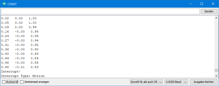
Output of ICM20948_10_wom_interrupt.ino
For the following output, I slowly straightened up the x-axis of the ICM-20948.
ICM20948_11_fsync_interrupt.ino
Here, the FSYNC pin is set up as an interrupt pin, which is triggered either on HIGH or LOW level. Depending on the setting, you must install a pull-up or pull-down resistor on FSYNC. Unlike the other interrupts, the FSYNC interrupt is not output at the interrupt pin. So you need to actively query the status.
#include <Wire.h>
#include <ICM20948_WE.h>
#define ICM20948_ADDR 0x68

/* There are several ways to create your ICM20948 object:
 * ICM20948_WE myIMU = ICM20948_WE()              -> uses Wire / I2C Address = 0x68
 * ICM20948_WE myIMU = ICM20948_WE(ICM20948_ADDR) -> uses Wire / ICM20948_ADDR
 * ICM20948_WE myIMU = ICM20948_WE(&wire2)        -> uses the TwoWire object wire2 / ICM20948_ADDR
 * ICM20948_WE myIMU = ICM20948_WE(&wire2, ICM20948_ADDR) -> all together
 * ICM20948_WE myIMU = ICM20948_WE(CS_PIN, spi);  -> uses SPI, spi is just a flag, see SPI example
 * ICM20948_WE myIMU = ICM20948_WE(&SPI, CS_PIN, spi);  -> uses SPI / passes the SPI object, spi is just a flag, see SPI example
 */
ICM20948_WE myIMU = ICM20948_WE(ICM20948_ADDR);

const int intPin = 2;
volatile bool fsyncEvent = false;

void setup() {
  //delay(2000); // maybe needed for some MCUs, in particular for startup after power off
  Wire.begin();
  Serial.begin(115200);
  while(!Serial) {}

  if(!myIMU.init()){
    Serial.println("ICM20948 does not respond");
  }
  else{
    Serial.println("ICM20948 is connected");
  }

  /* Set the interrupt pin:
   * ICM20948_ACT_LOW  = active-low
   * ICM20948_ACT_HIGH = active-high (default)
   */
   //myIMU.setIntPinPolarity(ICM20948_ACT_LOW);

  /*  If latch is enabled the interrupt pin level is held until the interrupt status
   *  is cleared. If latch is disabled the interrupt pulse is ~50µs (default).
   */
   myIMU.enableIntLatch(true);

  /* The interrupts ICM20948_FSYNC_INT, ICM20948_WOM_INT and ICM20948_DMP_INT can be
   * cleared by any read or will only be cleared if the interrupt status register is
   * read (default).
   */
   //myIMU.enableClearIntByAnyRead(true);

  /* Set the FSync interrupt pin:
   *  ICM20948_ACT_LOW  = interrupt if low
   *  ICM20948_ACT_HIGH = interrupt if high (default)
   */
   //myIMU.setFSyncIntPolarity(ICM20948_ACT_LOW);

  /* The following interrupts can be enabled or disabled:
   *  ICM20948_FSYNC_INT        FSYNC pin interrupt, can't propagate to the INT pin
   *  ICM20948_WOM_INT          Wake on motion
   *  ICM20948_DATA_READY_INT   New data available
   *  ICM20948_FIFO_OVF_INT     FIFO overflow
   */
  myIMU.enableInterrupt(ICM20948_FSYNC_INT);
  //myIMU.disableInterrupt(ICM20948_DATA_READY_INT);

  Serial.println("Pull down the FSYNC pin with a 10kOhm resistor.");
  Serial.println("A HIGH signal to pin FSYNC will then cause an interrupt - try it!");
}

void loop() {
  byte source = myIMU.readAndClearInterrupts();
  if(myIMU.checkInterrupt(source, ICM20948_FSYNC_INT)){
    Serial.println("Interrupt! Type: FSync Pin Interrupt");
  }
}
The sketch uses only one new function, which is setFSyncIntPolarity(). This determines whether the interrupt triggers at HIGH or LOW.
FIFO functions of the ICM-20948
The FIFO (first in, first out) is a kind of recorder for measurement data. The data that the ICM-20948 writes in first, it reads first – hence its name. According to the data sheet, the FIFO has a size of 512 bytes. However, I did not implement the DMP function. As a result, the FIFO grows to a comfortable 4096 bytes.
You define which data is written to the FIFO. This determines how many data records can be stored in the FIFO. An acceleration or gyroscope value is two bytes. It is always the raw data which stored. An x,y,z data triple therefore requires 6 bytes. I have implemented the following options:
- Acceleration values as complete triples – 682 complete triples fit (4096 / 6 = 682, rest 4) in the FIFO.
- Gyroscope values as complete triples – 682 complete triples fit.
- Acceleration and gyroscope values – max. 341 complete data sets (4096 / 12 = 341, rest 4).
- The ICM-20948 can also store gyroscope data from individual axes, temperatures or data from external sensors. However, I did not implement this to keep things simple.
If the FIFO is read, all FIFO data are shifted one after the other into a data register with a width of one byte. From there, the bytes are read one at a time (as when cigarette packs are taken from a cigarette vending machine) and “assembled” into meaningful data. However, for the individual bytes, it is not recognizable whether it is the MSB or LSB of an acceleration or a gyroscope value. So, you have to count and read the data in the right order. This can only be automated to a certain extent. And in order not to make it too complex and thus error-prone for the user, I did not implement all options.
ICM20948_12_FIFO_stop_when_full.ino
In this first FIFO sketch, the ICM-20948 stops data saving when the FIFO is full. This means that you specify the start of the recording. The recording duration depends on the data rate and the recorded data types. By the way, a combination of FIFO and cycle mode does not work.
When the FIFO is full, you can be informed about it by the FIFO overflow interrupt.
When recording acceleration and gyroscope data, the ICM-20948 always writes the acceleration data to the FIFO first. Since it stops in this example when the FIFO is full, the FIFO data begins with an acceleration value. This is different in the next example. For proper reading this is important!
In my example sketch, I record accelerometer and gyroscope data. The data rate of the gyroscope has priority. The sample rate divider is set to 20. Thus, the data rate is 1125/20 = 56.25 Hz. Since 341 records are recorded, the FIFO buffer overflows after about 6 seconds.
#include <Wire.h>
#include <ICM20948_WE.h>
#define ICM20948_ADDR 0x68

/* There are several ways to create your ICM20948 object:
 * ICM20948_WE myIMU = ICM20948_WE()              -> uses Wire / I2C Address = 0x68
 * ICM20948_WE myIMU = ICM20948_WE(ICM20948_ADDR) -> uses Wire / ICM20948_ADDR
 * ICM20948_WE myIMU = ICM20948_WE(&wire2)        -> uses the TwoWire object wire2 / ICM20948_ADDR
 * ICM20948_WE myIMU = ICM20948_WE(&wire2, ICM20948_ADDR) -> all together
 * ICM20948_WE myIMU = ICM20948_WE(CS_PIN, spi);  -> uses SPI, spi is just a flag, see SPI example
 * ICM20948_WE myIMU = ICM20948_WE(&SPI, CS_PIN, spi);  -> uses SPI / passes the SPI object, spi is just a flag, see SPI example
 */
ICM20948_WE myIMU = ICM20948_WE(ICM20948_ADDR);

const int intPin = 2;
volatile bool fifoFull = false;

void setup() {
  //delay(2000); // maybe needed for some MCUs, in particular for startup after power off
  Wire.begin();
  Serial.begin(115200);
  while(!Serial) {}

  if(!myIMU.init()){
    Serial.println("ICM20948 does not respond");
  }
  else{
    Serial.println("ICM20948 is connected");
  }

 //myIMU.setAccOffsets(-16330.0, 16450.0, -16600.0, 16180.0, -16520.0, 16690.0);

  /* The starting point, if you position the ICM20948 flat, is not necessarily 0g/0g/1g for x/y/z.
   * The autoOffset function measures offset. It assumes your ICM20948 is positioned flat with its
   * x,y-plane. The more you deviate from this, the less accurate will be your results.
   * It overwrites the zero points of setAccOffsets, but keeps the correction of the slope.
   * The function also measures the offset of the gyroscope data. The gyroscope offset does not
   * depend on the positioning.
   * This function needs to be called after setAccOffsets but before other settings since it will
   * overwrite settings!
   * You can query the offsets with the functions:
   * xyzFloat getAccOffsets() and xyzFloat getGyrOffsets()
   * You can apply the offsets using:
   * setAccOffsets(xyzFloat yourOffsets) and setGyrOffsets(xyzFloat yourOffsets)
   */
  Serial.println("Position your ICM20948 flat and don't move it - calibrating...");
  delay(1000);
  myIMU.autoOffsets();
  Serial.println("Done!");

  /*  The gyroscope data is not zero, even if you don't move the ICM20948.
   *  To start at zero, you can apply offset values. These are the gyroscope raw values you obtain
   *  using the +/- 250 degrees/s range.
   *  Use either autoOffset or setGyrOffsets, not both.
   */
  //myIMU.setGyrOffsets(-115.0, 130.0, 105.0);

  /* enables or disables the acceleration sensor, default: enabled */
  //myIMU.enableAcc(true);

  /*  ICM20948_ACC_RANGE_2G      2 g   (default)
   *  ICM20948_ACC_RANGE_4G      4 g
   *  ICM20948_ACC_RANGE_8G      8 g
   *  ICM20948_ACC_RANGE_16G    16 g
   */
  myIMU.setAccRange(ICM20948_ACC_RANGE_2G);

  /*  Choose a level for the Digital Low Pass Filter or switch it off.
   *  ICM20948_DLPF_0, ICM20948_DLPF_2, ...... ICM20948_DLPF_7, ICM20948_DLPF_OFF
   *
   *  IMPORTANT: This needs to be ICM20948_DLPF_7 if DLPF is used in cycle mode!
   *
   *  DLPF       3dB Bandwidth [Hz]      Output Rate [Hz]
   *    0              246.0               1125/(1+ASRD)
   *    1              246.0               1125/(1+ASRD)
   *    2              111.4               1125/(1+ASRD)
   *    3               50.4               1125/(1+ASRD)
   *    4               23.9               1125/(1+ASRD)
   *    5               11.5               1125/(1+ASRD)
   *    6                5.7               1125/(1+ASRD)
   *    7              473.0               1125/(1+ASRD)
   *    OFF           1209.0               4500
   *
   *    ASRD = Accelerometer Sample Rate Divider (0...4095)
   *    You achieve lowest noise using level 6
   */
  myIMU.setAccDLPF(ICM20948_DLPF_6);

  /*  Acceleration sample rate divider divides the output rate of the accelerometer.
   *  Sample rate = Basic sample rate / (1 + divider)
   *  It can only be applied if the corresponding DLPF is not off!
   *  Divider is a number 0...4095 (different range compared to gyroscope)
   *  If sample rates are set for the accelerometer and the gyroscope, the gyroscope
   *  sample rate has priority.
   */
  myIMU.setAccSampleRateDivider(20);

  /* enables or disables the gyroscope sensor, default: enabled */
  // myIMU.enableGyr(false);

  /*  ICM20948_GYRO_RANGE_250       250 degrees per second (default)
   *  ICM20948_GYRO_RANGE_500       500 degrees per second
   *  ICM20948_GYRO_RANGE_1000     1000 degrees per second
   *  ICM20948_GYRO_RANGE_2000     2000 degrees per second
   */
  myIMU.setGyrRange(ICM20948_GYRO_RANGE_250);

  /*  Choose a level for the Digital Low Pass Filter or switch it off.
   *  ICM20948_DLPF_0, ICM20948_DLPF_2, ...... ICM20948_DLPF_7, ICM20948_DLPF_OFF
   *
   *  DLPF       3dB Bandwidth [Hz]      Output Rate [Hz]
   *    0              196.6               1125/(1+GSRD)
   *    1              151.8               1125/(1+GSRD)
   *    2              119.5               1125/(1+GSRD)
   *    3               51.2               1125/(1+GSRD)
   *    4               23.9               1125/(1+GSRD)
   *    5               11.6               1125/(1+GSRD)
   *    6                5.7               1125/(1+GSRD)
   *    7              361.4               1125/(1+GSRD)
   *    OFF          12106.0               9000
   *
   *    GSRD = Gyroscope Sample Rate Divider (0...255)
   *    You achieve lowest noise using level 6
   */
  myIMU.setGyrDLPF(ICM20948_DLPF_6);

  /*  Gyroscope sample rate divider divides the output rate of the gyroscope.
   *  Sample rate = Basic sample rate / (1 + divider)
   *  It can only be applied if the corresponding DLPF is not OFF!
   *  Divider is a number 0...255
   *  If sample rates are set for the accelerometer and the gyroscope, the gyroscope
   *  sample rate has priority.
   */
  myIMU.setGyrSampleRateDivider(20);

  /*  Set the interrupt pin:
   *  ICM20948_ACT_LOW  = active-low
   *  ICM20948_ACT_HIGH = active-high (default)
   */
   //myIMU.setIntPinPolarity(ICM20948_ACT_LOW);

  /*  If latch is enabled the interrupt pin level is held until the interrupt status
   *  is cleared. If latch is disabled the interrupt pulse is ~50µs (default).
   */
  myIMU.enableIntLatch(true);

  /*  The interrupts ICM20948_FSYNC_INT, ICM20948_WOM_INT and ICM20948_DMP_INT can be
   *  cleared by any read or will only be cleared if the interrupt status register is
   *  read (default).
   */
  //myIMU.enableClearIntByAnyRead(true);

  /* The following interrupts can be enabled or disabled:
   *  ICM20948_FSYNC_INT        FSYNC pin interrupt, can't propagate to the INT pin
   *  ICM20948_WOM_INT          Wake on motion
   *  ICM20948_DATA_READY_INT   New data available
   *  ICM20948_FIFO_OVF_INT     FIFO overflow
   */
  myIMU.enableInterrupt(ICM20948_FIFO_OVF_INT);
  //myIMU.disableInterrupt(ICM20948_WOM_INT);

  /* enables the FIFO function, default: disabled */
  //myIMU.enableFifo(true);

  /* There are two different FIFO modes:
   *  ICM20948_CONTINUOUS --> samples are continuously stored in FIFO. If FIFO is full
   *  new data will replace the oldest.
   *  ICM20948_STOP_WHEN_FULL --> self-explaining
   */
  //myIMU.setFifoMode(ICM20948_STOP_WHEN_FULL); // used below, but explained here

  /* The argument of startFifo defines the data stored in the FIFO
   * ICM20948_FIFO_ACC --> Acceleration Data ist stored in FIFO
   * ICM20948_FIFO_GYR --> Gyroscope data is stored in FIFO
   * ICM20948_FIFO_ACC_GYR --> Acceleration and Gyroscope Data is stored in FIFO
   * The library does not (yet) support storing single gyroscope axes data, temperature
   * or data from slaves.
   */
  //myIMU.startFifo(ICM20948_FIFO_ACC); // used below, but explained here

  /* stopFifo():
   * - stops additional writes into Fifo
   * - clears the data type written into Fifo (acceleration and/or gyroscope
   */
  //myIMU.stopFifo();

  /* sets the Fifo counter to zero */
  //myIMU.resetFifo();


  attachInterrupt(digitalPinToInterrupt(intPin), eventISR, RISING);
  myIMU.setFifoMode(ICM20948_STOP_WHEN_FULL);
  myIMU.enableFifo(true);
  delay(100); // in some cases a delay after enabling Fifo makes sense
}

void loop() {
  countDown();
  myIMU.readAndClearInterrupts();
  fifoFull = false;
  myIMU.startFifo(ICM20948_FIFO_ACC_GYR);
  while(!fifoFull){}
  myIMU.stopFifo();
  printFifo();
  myIMU.resetFifo();

  Serial.println("For another series of measurements, enter any key and send");

  while(!(Serial.available())){}
  Serial.read();
  Serial.println();
 }

void printFifo(){
  int count = myIMU.getFifoCount();
  int dataSets = myIMU.getNumberOfFifoDataSets();
  Serial.print("Bytes in Fifo: ");
  Serial.println(count);
  Serial.print("Data Sets: ");
  Serial.println(dataSets);

  for(int i=0; i<dataSets; i++){
    xyzFloat gValue;
    xyzFloat gyr;
    myIMU.getGValuesFromFifo(&gValue);
    myIMU.getGyrValuesFromFifo(&gyr);
    Serial.print("Data set ");
    Serial.print(i+1);
    Serial.println(":");

    Serial.print(gValue.x);
    Serial.print("   ");
    Serial.print(gValue.y);
    Serial.print("   ");
    Serial.println(gValue.z);

    Serial.print(gyr.x);
    Serial.print("   ");
    Serial.print(gyr.y);
    Serial.print("   ");
    Serial.println(gyr.z);
  }
}

void countDown(){
  Serial.println("Move/turn your ICM20948 to obtain interesting data");
  Serial.println();
  delay(1000);
  Serial.print("Fifo collection begins in 3, ");
  delay(1000);
  Serial.print("2, ");
  delay(1000);
  Serial.print("1, ");
  delay(1000);
  Serial.println("Now!");
}

void eventISR() {
  fifoFull = true;
}
In my example, a countdown starts the FIFO. You can also choose other triggers, such as a WOM interrupt.
When the FIFO is full, this is indicated by an interrupt. Then the data is read and output. Then you can start a new FIFO recording by sending a character via the serial monitor.
New functions
The following new functions are used:
enableFifo()enables or disables the FIFO.- With
setFifoMode(), you determine whether you use the continuous or the “stop-when-full” mode. - You pass
startFiFo()the data types you want to write to the FIFO. This call of this function also starts the counter. - With
stopFifo(), you prevent that further data is written to the FIFO. This process is stopped anyway when the FIFO is full, but only temporarily. As soon as you start reading, free space is created in the FIFO. And that would be filled immediately with new data if you don’t callstopFifo(). getFifoCount()returns the number of bytes in the FIFO. If the FIFO is full, that’s 4096. But you could theoretically stop writing to the FIFO before it’s full.getNumberOfFifoDataSets()calculates the number of records in the FIFO. In this example, a data record consists of an x,y,z acceleration data triple and an x,y,z gyroscope data triple and that is 12 bytes.getGValuesFromFifo()reads an x,y,z triple of acceleration data and converts it into a g-value triple. Since the FIFO contains raw data, you must not change the parameters (i.e. range or offsets) between recording and reading.getGyrValuesFromFifo()reads an x,y,z gyroscope data triple (raw data) and converts it to rotation values (°/s).resetFifo()sets the FIFO counter to zero.
I need to stress once again that you must follow the order when reading the FIFO. In this example, you’ll alternately read acceleration data and gyroscope data and start with the acceleration data.
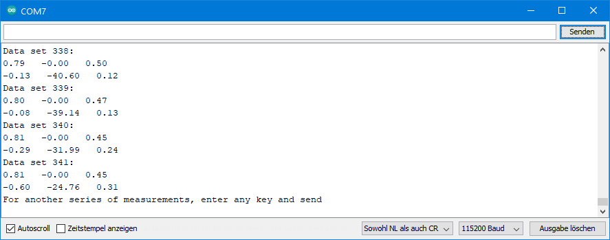
Output of ICM20949_12_FIFO_stop_when_full.ino
This is an excerpt of the output:
ICM20948_13_FIFO_continuous.ino
With this method, the FIFO continuously records the data types you have specified. So, here you do not determine the start, but the end. If the FIFO is full before you stop, it deletes the oldest data in favor of the new data.
The ICM-20948 always writes complete records to the FIFO. This means you have a defined end. The first data record, on the other hand, is incomplete. This is because the FIFO does not delete complete data sets. At 4096 bytes is brutally capped. Therefore, an additional function is needed in this case. It finds the beginning of the first complete data set when reading the FIFO.
The example sketch uses a WOM interrupt as the stop signal for the FIFO. Rotate the ICM-20948 to trigger the interrupt. Here I have set the sample rate divider to 10. This results in a data rate of 1125 / 11 = ~100 Hz. This means that under these conditions the FIFO contains the data of the last 3.4 seconds.
#include <Wire.h>
#include <ICM20948_WE.h>
#define ICM20948_ADDR 0x68
/* There are several ways to create your ICM20948 object:
* ICM20948_WE myIMU = ICM20948_WE() -> uses Wire / I2C Address = 0x68
* ICM20948_WE myIMU = ICM20948_WE(ICM20948_ADDR) -> uses Wire / ICM20948_ADDR
* ICM20948_WE myIMU = ICM20948_WE(&wire2) -> uses the TwoWire object wire2 / ICM20948_ADDR
* ICM20948_WE myIMU = ICM20948_WE(&wire2, ICM20948_ADDR) -> all together
* ICM20948_WE myIMU = ICM20948_WE(CS_PIN, spi); -> uses SPI, spi is just a flag, see SPI example
* ICM20948_WE myIMU = ICM20948_WE(&SPI, CS_PIN, spi); -> uses SPI / passes the SPI object, spi is just a flag, see SPI example
*/
ICM20948_WE myIMU = ICM20948_WE(ICM20948_ADDR);
const int intPin = 2;
volatile bool womEvent = false;
void setup() {
//delay(2000); // maybe needed for some MCUs, in particular for startup after power off
Wire.begin();
Serial.begin(115200);
while(!Serial) {}
if(!myIMU.init()){
Serial.println("ICM20948 does not respond");
}
else{
Serial.println("ICM20948 is connected");
}
/* This is a method to calibrate. You have to determine the minimum and maximum
* raw acceleration values of the axes determined in the range +/- 2 g.
* You call the function as follows: setAccOffsets(xMin,xMax,yMin,yMax,zMin,zMax);
* The parameters are floats.
* The calibration changes the slope / ratio of raw acceleration vs g. The zero point is
* set as (min + max)/2.
*/
//myIMU.setAccOffsets(-16330.0, 16450.0, -16600.0, 16180.0, -16520.0, 16690.0);
/* The starting point, if you position the ICM20948 flat, is not necessarily 0g/0g/1g for x/y/z.
* The autoOffset function measures offset. It assumes your ICM20948 is positioned flat with its
* x,y-plane. The more you deviate from this, the less accurate will be your results.
* It overwrites the zero points of setAccOffsets, but keeps the correction of the slope.
* The function also measures the offset of the gyroscope data. The gyroscope offset does not
* depend on the positioning.
* This function needs to be called after setAccOffsets but before other settings since it will
* overwrite settings!
* You can query the offsets with the functions:
* xyzFloat getAccOffsets() and xyzFloat getGyrOffsets()
* You can apply the offsets using:
* setAccOffsets(xyzFloat yourOffsets) and setGyrOffsets(xyzFloat yourOffsets)
*/
Serial.println("Position your ICM20948 flat and don't move it - calibrating...");
delay(1000);
myIMU.autoOffsets();
Serial.println("Done!");
/* The gyroscope data is not zero, even if you don't move the ICM20948.
* To start at zero, you can apply offset values. These are the gyroscope raw values you obtain
* using the +/- 250 degrees/s range.
* Use either autoOffset or setGyrOffsets, not both.
*/
//myIMU.setGyrOffsets(-115.0, 130.0, 105.0);
/* enables or disables the acceleration sensor, default: enabled */
// myIMU.enableAcc(true);
/* ICM20948_ACC_RANGE_2G 2 g (default)
* ICM20948_ACC_RANGE_4G 4 g
* ICM20948_ACC_RANGE_8G 8 g
* ICM20948_ACC_RANGE_16G 16 g
*/
myIMU.setAccRange(ICM20948_ACC_RANGE_2G);
/* Choose a level for the Digital Low Pass Filter or switch it off.
* ICM20948_DLPF_0, ICM20948_DLPF_2, ...... ICM20948_DLPF_7, ICM20948_DLPF_OFF
*
* IMPORTANT: This needs to be ICM20948_DLPF_7 if DLPF is used in cycle mode!
*
* DLPF 3dB Bandwidth [Hz] Output Rate [Hz]
* 0 246.0 1125/(1+ASRD)
* 1 246.0 1125/(1+ASRD)
* 2 111.4 1125/(1+ASRD)
* 3 50.4 1125/(1+ASRD)
* 4 23.9 1125/(1+ASRD)
* 5 11.5 1125/(1+ASRD)
* 6 5.7 1125/(1+ASRD)
* 7 473.0 1125/(1+ASRD)
* OFF 1209.0 4500
*
* ASRD = Accelerometer Sample Rate Divider (0...4095)
* You achieve lowest noise using level 6
*/
myIMU.setAccDLPF(ICM20948_DLPF_6);
/* Acceleration sample rate divider divides the output rate of the accelerometer.
* Sample rate = Basic sample rate / (1 + divider)
* It can only be applied if the corresponding DLPF is not off!
* Divider is a number 0...4095 (different range compared to gyroscope)
* If sample rates are set for the accelerometer and the gyroscope, the gyroscope
* sample rate has priority.
*/
myIMU.setAccSampleRateDivider(10);
/* enables or disables the gyroscope sensor, default: enabled */
// myIMU.enableGyr(false);
/* ICM20948_GYRO_RANGE_250 250 degrees per second (default)
* ICM20948_GYRO_RANGE_500 500 degrees per second
* ICM20948_GYRO_RANGE_1000 1000 degrees per second
* ICM20948_GYRO_RANGE_2000 2000 degrees per second
*/
//myIMU.setGyrRange(ICM20948_GYRO_RANGE_250);
/* Choose a level for the Digital Low Pass Filter or switch it off.
* ICM20948_DLPF_0, ICM20948_DLPF_2, ...... ICM20948_DLPF_7, ICM20948_DLPF_OFF
*
* DLPF 3dB Bandwidth [Hz] Output Rate [Hz]
* 0 196.6 1125/(1+GSRD)
* 1 151.8 1125/(1+GSRD)
* 2 119.5 1125/(1+GSRD)
* 3 51.2 1125/(1+GSRD)
* 4 23.9 1125/(1+GSRD)
* 5 11.6 1125/(1+GSRD)
* 6 5.7 1125/(1+GSRD)
* 7 361.4 1125/(1+GSRD)
* OFF 12106.0 9000
*
* GSRD = Gyroscope Sample Rate Divider (0...255)
* You achieve lowest noise using level 6
*/
myIMU.setGyrDLPF(ICM20948_DLPF_6);
/* Gyroscope sample rate divider divides the output rate of the gyroscope.
* Sample rate = Basic sample rate / (1 + divider)
* It can only be applied if the corresponding DLPF is not OFF!
* Divider is a number 0...255
* If sample rates are set for the accelerometer and the gyroscope, the gyroscope
* sample rate has priority.
*/
myIMU.setGyrSampleRateDivider(10);
/* Set the interrupt pin:
* ICM20948_ACT_LOW = active-low
* ICM20948_ACT_HIGH = active-high (default)
*/
//myIMU.setIntPinPolarity(ICM20948_ACT_LOW);
/* If latch is enabled the interrupt pin level is held until the interrupt status
* is cleared. If latch is disabled the interrupt pulse is ~50µs (default).
*/
myIMU.enableIntLatch(true);
/* The interrupts ICM20948_FSYNC_INT, ICM20948_WOM_INT and ICM20948_DMP_INT can be
* cleared by any read or will only be cleared if the interrupt status register is
* read (default).
*/
//myIMU.enableClearIntByAnyRead(true);
/* The following interrupts can be enabled or disabled:
* ICM20948_FSYNC_INT FSYNC pin interrupt, can't propagate to the INT pin
* ICM20948_WOM_INT Wake on motion
* ICM20948_DATA_READY_INT New data available
* ICM20948_FIFO_OVF_INT FIFO overflow
*/
myIMU.enableInterrupt(ICM20948_WOM_INT);
//myIMU.disableInterrupt(ICM20948_WOM_INT);
/* setWakeOnMotionThreshold sets the limit (first argument) for a wake on
* motion interrupt and defines the WOM mode (second argument). The limit
* is a number between 1 and 255 with 1 = 4 mg (milli-g) and 255 = 1020 mg.
* You can choose from two modes:
* ICM20948_WOM_COMP_DISABLE = compare the sample with the initial sample (default).
* ICM20948_WOM_COMP_ENABLE = compare the sampe with the previous sample.
*/
myIMU.setWakeOnMotionThreshold(128, ICM20948_WOM_COMP_DISABLE);
/* enables the FIFO function, default: disabled */
// myIMU.enableFifo(true); // explained here, used below
/* There are two different FIFO modes:
* ICM20948_CONTINUOUS --> samples are continuously stored in FIFO. If FIFO is full
* new data will replace the oldest.
* ICM20948_STOP_WHEN_FULL --> self-explaining
*/
//myIMU.setFifoMode(ICM20948_STOP_WHEN_FULL); // used below, but explained here
/* The argument of startFifo defines the data stored in the FIFO
* ICM20948_FIFO_ACC --> Acceleration Data ist stored in FIFO
* ICM20948_FIFO_GYR --> Gyroscope data is stored in FIFO
* ICM20948_FIFO_ACC_GYR --> Acceleration and Gyroscope Data is stored in FIFO
* The library does not (yet) support storing single gyroscope axes data, temperature
* or data from slaves.
*/
//myIMU.startFifo(ICM20948_FIFO_ACC); // used below, but explained here
/* stopFifo():
* - stops additional writes into Fifo
* - clears the data type written into Fifo (acceleration and/or gyroscope)
*/
//myIMU.stopFifo(); // explained here, used below
/* sets the Fifo counter to zero */
//myIMU.resetFifo(); // explained here, used below
attachInterrupt(digitalPinToInterrupt(intPin), eventISR, RISING);
myIMU.readAndClearInterrupts();
womEvent = false;
myIMU.setFifoMode(ICM20948_CONTINUOUS);
myIMU.enableFifo(true);
delay(100); // in some cases a delay after enabling Fifo makes sense
myIMU.startFifo(ICM20948_FIFO_ACC_GYR);
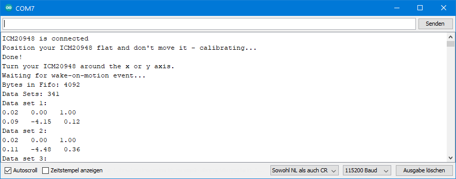
Serial.println("Turn your ICM20948 around the x or y axis.");
Serial.println("Waiting for wake-on-motion event...");
}
void loop() {
if(womEvent){
myIMU.stopFifo();
printFifo();
myIMU.resetFifo();
myIMU.startFifo(ICM20948_FIFO_ACC_GYR);
Serial.println("For another series of measurements, enter any key and send");
while(!(Serial.available())){}
Serial.read();
Serial.println();
myIMU.readAndClearInterrupts();
womEvent = false;
}
}
void printFifo(){
myIMU.findFifoBegin(); /* this is needed for continuous Fifo mode. The Fifo buffer ends with a
complete data set, but it starts is within a data set. */
int count = myIMU.getFifoCount();
int dataSets = myIMU.getNumberOfFifoDataSets();
Serial.print("Bytes in Fifo: ");
Serial.println(count);
Serial.print("Data Sets: ");
Serial.println(dataSets);
for(int i=0; i<dataSets; i++){
/* if you read acceleration (g) and gyroscope values you need to start with g values */
xyzFloat gValue;
xyzFloat gyr;
myIMU.getGValuesFromFifo(&gValue);
myIMU.getGyrValuesFromFifo(&gyr);
Serial.print("Data set ");
Serial.print(i+1);
Serial.println(":");
Serial.print(gValue.x);
Serial.print(" ");
Serial.print(gValue.y);
Serial.print(" ");
Serial.println(gValue.z);
Serial.print(gyr.x);
Serial.print(" ");
Serial.print(gyr.y);
Serial.print(" ");
Serial.println(gyr.z);
}
}
void eventISR() {
womEvent = true;
}
The sketch uses only one new function, which is findFifoBegin(). It calculates where the first complete record begins in the FIFO. Then it reads the data up to that point and discards it. Therefore, getFifoCount() – after calling findFifoBegin() – won’t return 4096. Just try and call getFifoCount() before findFifoBegin() and see what happens.
Output of ICM20948_13_FIFO_continuous.ino
This is an excerpt of the output on the serial monitor:
If you feel like it, play around a bit with the FIFO parameters. For example, you could select a different sample rate or stop the FIFO before it’s full. For the latter, you will see that reading still works. Or try to only write acceleration or gyroscope data to the FIFO.
ICM20948_14_blank_all_settings
This is not a finished sketch that does anything special. Here I have just listed all the functions for setting the ICM-20948. I thought this could be a good basis for your sketches.
Hi Wolfgang, is there any way to have the gyro (x) to generate an interrupt ? I’m sharing the i2c with another device so having an interrupt configured just to an gyro axis would be great. I know i can use this port to communicate with several devices, nevertheless in a certain moment I am using my other device in a continuous mode.
Hi Pablo, I am sorry, but there is no interrupt for the gyroscope. There is only the WOM (wake-on-motion) interrupt for the accelerometer.
Hi Wolfgang !
First, thank you for your ICM-20498 library – it is the only one I have found that works perfectly and reliably – I am using it with an Adafruit QT PY ESP32 S3.
Second, I notice you have exposed Pitch and Roll in the library, but not Yaw. Is there a reason for this? Would you be able to include this in a future update?
Best
Andy
Hi Andy,
thanks for the kind feedback! The problem with the Yaw angle is that you can’t calculate it from the acceleration sensors. When the sensor is positioned flat, the x and the y accleration is 0 and z is 1g. If rotate the z-axis (change the Yaw angle) nothing will change. In theory you could calibrate the magnetometer to determine the Yaw angle. This is not too difficult if the module is positioned flat, but if you change the z-angle things become difficult. Another option would be to measure the gyroscope values with high frequency to estimate the Yaw angle. Another option is to combine all values and use quaternions but I have not found the time to go into this complex topic. So, sorry, in the near future I won’t implement Yaw angle calculation.
Cheers, Wolfgang
I have edited the library Locally- spent good amount of times and got yaw values as well. Maybe you can contact me on telegram @nafizali153 for any help.
Hi,I appreciate contributions. But I am not using Telegramm. You could use GitHub or you just send me your code via e-mail: wolfgang.ewald@wolles-elektronikkiste.de
Hi Nafiz
Great news !
I don’t have Telegram I’m afraid and for various reasons I’d like to stay on this platform – are you able to share your work?
Best
Andy
Hallo Herr Ewald,
ich Rahmen meiner Bachelorarbeit benutze ich diesen Sensor und Ihr Code war äußerst hilfreich zum Verständnis.
Wissen Sie, in welcher Sample Rate ohne andere Einstellungen die Daten aktualisiert werden? Also wenn ich jede Millisekunde die Register abfrage, kann ich mir dann sicher sein, dass neue Daten vorhanden sind?
Wo erfährt man die genaue Aktualisierungsrate?
Hi Timon, schau al in den ersten Teil des Beitrages und/oder in den Beispielsketch ICM20948_14_blank_all_settings.ino. Dort findest du, dass die Ausgabegeschwindigkeit über den Sample Rate Divider, also setGyrSampleRateDivider(); bzw. setAccSampleRateDivider(); im Zusammenspiel mit dem Digital Low Pass Filter, also setGyrDLPF() bzw. setAccDLPF() eingestellt wird. Die schnellste Datenrate bekommst du, wenn der DLPF abgeschaltet ist, allerdings hast du dann auch das höchste Rauschen. Wenn der DLPF an ist, dann ist die Ausgaberate 1125 Hz / (1+SampleRateDivider). D.h. nur bei DLPF Stufe 0 bekommst du jede Millisekunde einen neuen Wert. Viel Spaß und Erfolg bei der Bachelorarbeit!
VG, Wolfgang
Hi,
First of all thank you for the helpful tutorial!
Do you know the time interval for the whole FIFO (4096B) to be read
when I2C speed is 400kHz? Theoretically if my calculations are right
Byte Read Time = 2.5usec/bit * 8 bits/byte = 20usec/byte. Then for FIFO 4096 Bytes
FIFO Read Time = 20usec/byte * 4096 bytes = 82 msec
In that case if the sensor’s sample rate is set to 50Hz the FIFO will miss 5 samples every time until the whole FIFO is read so that to start storing samples again
Thank you for your time
Hi, it’s a bit more complex. There is more time needed to read data via I2C. This is because before you can read anything you also need query the data. This means the I2C address needs to be sent as well as the register. This is additional two bytes. In theory you could read all 4096 bytes in one go and then this effect would be diluted. But how could you handle 4096 bytes in one variable?
You also need to consider that you will not only query the FIFO data, but you will also do something with the data like saving it somewhere or displaying it. In my example sketches I display the value on the serial monitor this is a very slow process which takes even more time than requesting the data.
Your question suggests that you want to continuously use the FIFO, i.e. fill it, read it, fill it , read etc.. Wouldn’t it be better to not use the FIFO in that case and directly read the measured values?
And last comment: You can measure how long things take with millis().
Hope this helps!?
Yes, the reason I want to continuously use the FIFO is because I can put my uController to sleep and not polling for sensor data. That way the uController would be awake every 6.8sec save the data to a storage device and go back to sleep for another 6.8sec.
“But how could you handle 4096 bytes in one variable?”. I was thinking of using a burst read function.
If would write a function that burst reads 4096 the function would require a return value of 4096. The complete RAM of an Atmega328P is 2 kbytes. That is what I mean with “how to handle 4096 byte in one variable”.
I have improved the efficiency of reading the FIFO. Now 6 bytes are read in one go. This is not yet what you would like to have, I know.
But I had a closer look and for implementig the burst read I would have to change many functions. The burst read itself is no problem. It’s related with the way I calculate the corrected data from the raw data which would make a change quite complex.
The new version is available on GitHub now. If you use the Arduino IDE it can take few days until the library will be updated.
What I will do is implement SPI as an alternative to I2C. That will be much faster. But this takes a bit more time than my quick improvement, so I am careful with promising a date. Will try it within the next few weeks.
I found time and implemented SPI. With an Arduino Nano (SPI clock 4 MHz) it now takes 38 ms to read a full FIFO of 4096 bytes. The new version is available on GitHub.