Über den Beitrag

Dieses ist die Fortsetzung des ersten Teils meines Beitrages über den 9-Achsensensor ICM-20948. Im ersten Teil bin ich zunächst auf die technischen Eigenschaften eingegangen. Dann habe ich angefangen, meine Bibliothek ICM20948_WE vorzustellen. Diese könnt ihr hier von GitHub herunterladen oder über den Bibliotheksmanager der Arduino IDE installieren.
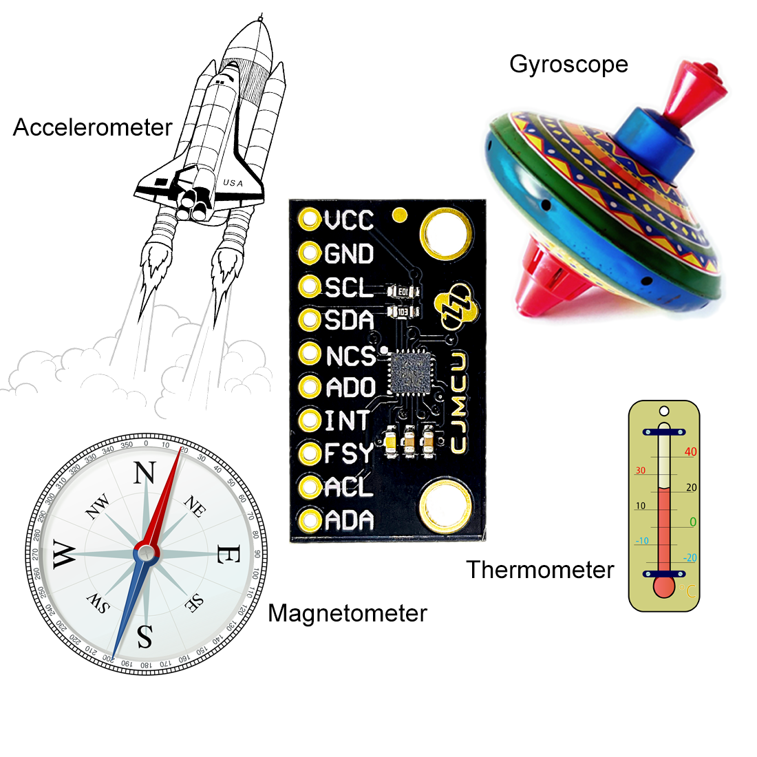
Ich hatte gezeigt, wie ihr die Daten des Beschleunigungssensors, des Gyroskops, des Magnetometers und des Thermometers abruft und wie die Kalibrierung funktioniert. Darüber hinaus habe ich Funktionen zur Messung von Neigungswinkeln vorgestellt.
In diesem Teil geht es um die folgenden Themen:
- Cycle Modus
- Interrupts
- FIFO Puffer
Wie im ersten Teil stelle ich die Funktionen anhand von Beispielsketchen vor.
ICM20948_08_cycle.ino
Im Cycle Modus schlafen die Sensoren zwischen den Messungen. Dadurch spart ihr wertvollen Strom bei batteriebetriebenen Projekten. Für den folgenden Beispielsketch habe ich einen Stromverbrauch von 2.3 mA ermittelt. Mit deaktiviertem Cycle Modus lag der Stromverbrauch hingegen bei 4.4 mA.
Ihr aktiviert den Cycle Modus mit enableCycle(parameter). Über den Parameter (siehe Sketch) legt ihr fest, welche Sensoren in den Cycle Modus gehen sollen.
#include <Wire.h>
#include <ICM20948_WE.h>
#define ICM20948_ADDR 0x68

/* There are several ways to create your ICM20948 object:
 * ICM20948_WE myIMU = ICM20948_WE()              -> uses Wire / I2C Address = 0x68
 * ICM20948_WE myIMU = ICM20948_WE(ICM20948_ADDR) -> uses Wire / ICM20948_ADDR
 * ICM20948_WE myIMU = ICM20948_WE(&wire2)        -> uses the TwoWire object wire2 / ICM20948_ADDR
 * ICM20948_WE myIMU = ICM20948_WE(&wire2, ICM20948_ADDR) -> all together
 * ICM20948_WE myIMU = ICM20948_WE(CS_PIN, spi);  -> uses SPI, spi is just a flag, see SPI example
 * ICM20948_WE myIMU = ICM20948_WE(&SPI, CS_PIN, spi);  -> uses SPI / passes the SPI object, spi is just a flag, see SPI example
 */
ICM20948_WE myIMU = ICM20948_WE(ICM20948_ADDR);

void setup() {
  //delay(2000); // maybe needed for some MCUs, in particular for startup after power off
  Wire.begin();
  Serial.begin(115200);
  while(!Serial) {}

  if(!myIMU.init()){
    Serial.println("ICM20948 does not respond");
  }
  else{
    Serial.println("ICM20948 is connected");
  }

  if (!myIMU.initMagnetometer()) {
    Serial.println("Magnetometer does not respond");
  }
  else {
    Serial.println("Magnetometer is connected");
  }

  /*  This is a method to calibrate. You have to determine the minimum and maximum
   *  raw acceleration values of the axes determined in the range +/- 2 g.
   *  You call the function as follows: setAccOffsets(xMin,xMax,yMin,yMax,zMin,zMax);
   *  The parameters are floats.
   *  The calibration changes the slope / ratio of raw acceleration vs g. The zero point is
   *  set as (min + max)/2.
   */
//  myIMU.setAccOffsets(-16330.0, 16450.0, -16600.0, 16180.0, -16640.0, 16560.0);

  /*  The starting point, if you position the ICM20948 flat, is not necessarily 0g/0g/1g for x/y/z.
   *  The autoOffset function measures offset. It assumes your ICM20948 is positioned flat with its
   *  x,y-plane. The more you deviate from this, the less accurate will be your results.
   *  It overwrites the zero points of setAccOffsets, but keeps the correction of the slope.
   *  The function also measures the offset of the gyroscope data. The gyroscope offset does not
   *  depend on the positioning.
   *  This function needs to be called after setAccOffsets but before other settings since it will
   *  overwrite settings!
   *  You can query the offsets with the functions:
   *  xyzFloat getAccOffsets() and xyzFloat getGyrOffsets()
   *  You can apply the offsets using:
   *  setAccOffsets(xyzFloat yourOffsets) and setGyrOffsets(xyzFloat yourOffsets)
   */
//  Serial.println("Position your ICM20948 flat and don't move it - calibrating...");
//  delay(1000);
//  myIMU.autoOffsets();
//  Serial.println("Done!");

  /*  The gyroscope data is not zero, even if you don't move the ICM20948.
   *  To start at zero, you can apply offset values. These are the gyroscope raw values you obtain
   *  using the +/- 250 degrees/s range.
   *  Use either autoOffset or setGyrOffsets, not both.
   */
//  myIMU.setGyrOffsets(-115.0, 130.0, 105.0);


  /* enables or disables the acceleration sensor, default: enabled */
  //myIMU.enableAcc(false);

  /*  ICM20948_ACC_RANGE_2G      2 g   (default)
   *  ICM20948_ACC_RANGE_4G      4 g
   *  ICM20948_ACC_RANGE_8G      8 g
   *  ICM20948_ACC_RANGE_16G    16 g
   */
  myIMU.setAccRange(ICM20948_ACC_RANGE_2G);

  /*  Choose a level for the Digital Low Pass Filter or switch it off.
   *  ICM20948_DLPF_0, ICM20948_DLPF_2, ...... ICM20948_DLPF_7, ICM20948_DLPF_OFF
   *
   *  IMPORTANT: This needs to be ICM20948_DLPF_7 if DLPF is used in cycle mode!
   *
   *  DLPF       3dB Bandwidth [Hz]      Output Rate [Hz]
   *    0              246.0               1125/(1+ASRD)
   *    1              246.0               1125/(1+ASRD)
   *    2              111.4               1125/(1+ASRD)
   *    3               50.4               1125/(1+ASRD)
   *    4               23.9               1125/(1+ASRD)
   *    5               11.5               1125/(1+ASRD)
   *    6                5.7               1125/(1+ASRD)
   *    7              473.0               1125/(1+ASRD)
   *    OFF           1209.0               4500
   *
   *    ASRD = Accelerometer Sample Rate Divider (0...4095)
   *    You achieve lowest noise using level 6
   */
  myIMU.setAccDLPF(ICM20948_DLPF_7);

  /*  Acceleration sample rate divider divides the output rate of the accelerometer.
   *  Sample rate = Basic sample rate / (1 + divider)
   *  It can only be applied if the corresponding DLPF is not off!
   *  Divider is a number 0...4095 (different range compared to gyroscope)
   *  If sample rates are set for the accelerometer and the gyroscope, the gyroscope
   *  sample rate has priority.
   */
  myIMU.setAccSampleRateDivider(2048);

  /* enables or disables the gyroscope sensor, default: enabled */
  //myIMU.enableGyr(false);

  /*  ICM20948_GYRO_RANGE_250       250 degrees per second (default)
   *  ICM20948_GYRO_RANGE_500       500 degrees per second
   *  ICM20948_GYRO_RANGE_1000     1000 degrees per second
   *  ICM20948_GYRO_RANGE_2000     2000 degrees per second
   */
 // myIMU.setGyrRange(ICM20948_GYRO_RANGE_250);

  /*  Choose a level for the Digital Low Pass Filter or switch it off.
   *  ICM20948_DLPF_0, ICM20948_DLPF_2, ...... ICM20948_DLPF_7, ICM20948_DLPF_OFF
   *
   *  DLPF       3dB Bandwidth [Hz]      Output Rate [Hz]
   *    0              196.6               1125/(1+GSRD)
   *    1              151.8               1125/(1+GSRD)
   *    2              119.5               1125/(1+GSRD)
   *    3               51.2               1125/(1+GSRD)
   *    4               23.9               1125/(1+GSRD)
   *    5               11.6               1125/(1+GSRD)
   *    6                5.7               1125/(1+GSRD)
   *    7              361.4               1125/(1+GSRD)
   *    OFF          12106.0               9000
   *
   *    GSRD = Gyroscope Sample Rate Divider (0...255)
   *    You achieve lowest noise using level 6
   */
  myIMU.setGyrDLPF(ICM20948_DLPF_6);

  /*  Gyroscope sample rate divider divides the output rate of the gyroscope.
   *  Sample rate = Basic sample rate / (1 + divider)
   *  It can only be applied if the corresponding DLPF is not OFF!
   *  Divider is a number 0...255
   *  If sample rates are set for the accelerometer and the gyroscope, the gyroscope
   *  sample rate has priority.
   */
  myIMU.setGyrSampleRateDivider(255);

  /* In cycle mode the sensors wake up in the frequency of sample rate. You can define
   * which sensors shall work in cycle mode.
   *
   *  ICM20948_NO_CYCLE
   *  ICM20948_GYR_CYCLE
   *  ICM20948_ACC_CYCLE
   *  ICM20948_ACC_GYR_CYCLE
   *  ICM20948_ACC_GYR_I2C_MST_CYCLE
   */
  myIMU.enableCycle(ICM20948_ACC_GYR_I2C_MST_CYCLE);

  /* The Low Power Mode does not work if DLPF is enabled */
  //myIMU.enableLowPower(true);

  /* In cycle mode you need to set the number of measured values for the gyroscope
   * to be averaged. You can select 1,2,4,8,16,32,64 or 128:
   * ICM20948_GYR_AVG_1, ICM20948_GYR_AVG_2, ..... , ICM20948_GYR_AVG_128
   * The on-time for measurements increases with the number of samples to be averaged:
   * 1 -> 1.15 ms, 2 -> 1.59 ms, .... , 128 -> 57.59 ms (see data sheet)
   */
  myIMU.setGyrAverageInCycleMode(ICM20948_GYR_AVG_1);

  /* In cycle mode you need to set the number of measured values for the accelerometer
   * to be averaged. You can select 4,8,16,32:
   * ICM20948_ACC_AVG_4, ICM20948_ACC_AVG_8, ICM20948_ACC_AVG_16, ICM20948_ACC_AVG_32
   * The on-time for measurements increases with the number of samples to be averaged:
   * 4 -> 1.488 ms, 8 -> 2.377 ms, 16 -> 4.154 ms , 32 -> 7.71 ms (see data sheet)
   * If DLPF is OFF, then with ICM20948_ACC_AVG_4 only one sample is taken!
   */
  myIMU.setAccAverageInCycleMode(ICM20948_ACC_AVG_4);

  /* setI2CMstSampleRate sets the rate of the devices controlled by the I2C master,
   * i.e. the magnetometer. It is not the internal sample rate of the magnetometer, but
   * the output rate of the I2C master. Allowed values are x = 0...15. The sample rate is
   * 1.1 kHz / (2^x). Example: x = 13 => Sample rate = 1.1 kHz / 8192 = ~0.1343 Hz,
   * or: data output every ~7.45 seconds.
   */
  myIMU.setI2CMstSampleRate(13);
}

void loop() {
  xyzFloat gValue;
  xyzFloat gyrValue;
  xyzFloat magValue;
  myIMU.readSensor();
  myIMU.getGValues(&gValue);
  myIMU.getGyrValues(&gyrValue);
  myIMU.getMagValues(&magValue);

  Serial.println("g-values (x,y,z):");
  Serial.print(gValue.x);
  Serial.print("   ");
  Serial.print(gValue.y);
  Serial.print("   ");
  Serial.println(gValue.z);

  Serial.println("Gyroscope (x,y,z):");
  Serial.print(gyrValue.x);
  Serial.print("   ");
  Serial.print(gyrValue.y);
  Serial.print("   ");
  Serial.println(gyrValue.z);

  Serial.println("Magnetometer Data in µTesla: ");
  Serial.print(magValue.x);
  Serial.print("   ");
  Serial.print(magValue.y);
  Serial.print("   ");
  Serial.println(magValue.z);

  Serial.println();

  delay(500);
}
Mit den Funktionen setAccAverageInCycleMode() und setGyrAverageInCycleMode() legt ihr die Anzahl an Einzelmessungen fest, aus denen das Ergebnis gemittelt wird. Jedoch müsst ihr bedenken, dass zu viele Einzelmessungen den Energiespareffekt verwässern.
Es gibt noch ein paar Punkte zu beachten:
- Bei aktiviertem DLPF misst der Beschleunigungssensor im Cycle Modus falsche Werte.
- Der Sample Rate Divider des Beschleunigungssensors sollte bei ausgeschaltetem DLPF laut Datenblatt nicht funktionieren – tut er aber!
- Zusätzlich zum Cycle Modus könnt ihr mit
enableLowPower(true/false)einen Low Power Modus an- beziehungsweise abschalten. Das lieferte bei obigem Sketch weitere 0.2 mA Ersparnis. Die Funktion zeigt nur einen Effekt, wenn der Cycle Modus aktiv ist. Was der Low Power Modus außer Strom zu sparen genau bewirkt, das habe ich nicht herausgefunden. setI2CSampleMasterRate(x)bestimmt die Frequenz, in der die Messwerte der Sensoren abgefragt werden, die über die I2C Hilfsschnittstelle angesprochen werden. Die Frequenz ist 1100/2x kHz (0.134 Hz im Beispielsketch). Auch mit dieser Funktion spart ihr Strom.
- In meiner Bibliothek ist die Funktion nur für das Magnetometer relevant.
Interrupts des ICM-20948 nutzen
Die folgenden Interrupts des ICM-20948 habe ich implementiert:
- Data Ready: löst aus, wenn neue Messwerte vorliegen.
- Wake on Motion („WOM“): löst aus, wenn ein von euch festgelegter Beschleunigungswert überschritten wird.
- FIFO Overflow: löst aus, wenn der FIFO Speicher voll ist (512 Bytes / 4096 Bytes).
- FSYNC: löst aus, wenn ein HIGH oder LOW an FSYNC anliegt.
ICM20948_09_data_ready_interrupt.ino
Im folgenden Sketch steuert der Data Ready Interrupt die Ausgabe der Messwerte. Ich habe nur den Beschleunigungssensor aktiviert. Den Sample Rate Divider habe ich auf 4095 eingestellt und den DLPF 1 gewählt. Daraus ergibt sich eine Ausgabefrequenz von 1125 / 4096 = ~0.27 Hz.
#include <Wire.h>
#include <ICM20948_WE.h>
#define ICM20948_ADDR 0x68

/* There are several ways to create your ICM20948 object:
 * ICM20948_WE myIMU = ICM20948_WE()              -> uses Wire / I2C Address = 0x68
 * ICM20948_WE myIMU = ICM20948_WE(ICM20948_ADDR) -> uses Wire / ICM20948_ADDR
 * ICM20948_WE myIMU = ICM20948_WE(&wire2)        -> uses the TwoWire object wire2 / ICM20948_ADDR
 * ICM20948_WE myIMU = ICM20948_WE(&wire2, ICM20948_ADDR) -> all together
 * ICM20948_WE myIMU = ICM20948_WE(CS_PIN, spi);  -> uses SPI, spi is just a flag, see SPI example
 * ICM20948_WE myIMU = ICM20948_WE(&SPI, CS_PIN, spi);  -> uses SPI / passes the SPI object, spi is just a flag, see SPI example
 */
ICM20948_WE myIMU = ICM20948_WE(ICM20948_ADDR);

const int intPin = 2;
volatile bool dataReady = false;

void setup() {
  //delay(2000); // maybe needed for some MCUs, in particular for startup after power off
  Wire.begin();
  Serial.begin(115200);
  while(!Serial) {}

  if(!myIMU.init()){
    Serial.println("ICM20948 does not respond");
  }
  else{
    Serial.println("ICM20948 is connected");
  }

  /*  This is a method to calibrate. You have to determine the minimum and maximum
   *  raw acceleration values of the axes determined in the range +/- 2 g.
   *  You call the function as follows: setAccOffsets(xMin,xMax,yMin,yMax,zMin,zMax);
   *  The parameters are floats.
   *  The calibration changes the slope / ratio of raw acceleration vs g. The zero point is
   *  set as (min + max)/2.
   */
//  myIMU.setAccOffsets(-16330.0, 16450.0, -16600.0, 16180.0, -16520.0, 16690.0);

  /*  The starting point, if you position the ICM20948 flat, is not necessarily 0g/0g/1g for x/y/z.
   *  The autoOffset function measures offset. It assumes your ICM20948 is positioned flat with its
   *  x,y-plane. The more you deviate from this, the less accurate will be your results.
   *  It overwrites the zero points of setAccOffsets, but keeps the correction of the slope.
   *  The function also measures the offset of the gyroscope data. The gyroscope offset does not
   *  depend on the positioning.
   *  This function needs to be called after setAccOffsets but before other settings since it will
   *  overwrite settings!
   *  You can query the offsets with the functions:
   *  xyzFloat getAccOffsets() and xyzFloat getGyrOffsets()
   *  You can apply the offsets using:
   *  setAccOffsets(xyzFloat yourOffsets) and setGyrOffsets(xyzFloat yourOffsets)
   */
//  Serial.println("Position your ICM20948 flat and don't move it - calibrating...");
//  delay(1000);
//  myIMU.autoOffsets();
//  Serial.println("Done!");

  /*  The gyroscope data is not zero, even if you don't move the ICM20948.
   *  To start at zero, you can apply offset values. These are the gyroscope raw values you obtain
   *  using the +/- 250 degrees/s range.
   *  Use either autoOffset or setGyrOffsets, not both.
   */
//  myIMU.setGyrOffsets(-115.0, 130.0, 105.0);


  /* enables or disables the acceleration sensor, default: enabled */
  //myIMU.enableAcc(false);

  /*  ICM20948_ACC_RANGE_2G      2 g   (default)
   *  ICM20948_ACC_RANGE_4G      4 g
   *  ICM20948_ACC_RANGE_8G      8 g
   *  ICM20948_ACC_RANGE_16G    16 g
   */
  myIMU.setAccRange(ICM20948_ACC_RANGE_2G);

  /*  Choose a level for the Digital Low Pass Filter or switch it off.
   *  ICM20948_DLPF_0, ICM20948_DLPF_2, ...... ICM20948_DLPF_7, ICM20948_DLPF_OFF
   *
   *  IMPORTANT: This needs to be ICM20948_DLPF_7 if DLPF is used in cycle mode!
   *
   *  DLPF       3dB Bandwidth [Hz]      Output Rate [Hz]
   *    0              246.0               1125/(1+ASRD)
   *    1              246.0               1125/(1+ASRD)
   *    2              111.4               1125/(1+ASRD)
   *    3               50.4               1125/(1+ASRD)
   *    4               23.9               1125/(1+ASRD)
   *    5               11.5               1125/(1+ASRD)
   *    6                5.7               1125/(1+ASRD)
   *    7              473.0               1125/(1+ASRD)
   *    OFF           1209.0               4500
   *
   *    ASRD = Accelerometer Sample Rate Divider (0...4095)
   *    You achieve lowest noise using level 6
   */
  myIMU.setAccDLPF(ICM20948_DLPF_1);

  /*  Acceleration sample rate divider divides the output rate of the accelerometer.
   *  Sample rate = Basic sample rate / (1 + divider)
   *  It can only be applied if the corresponding DLPF is not off!
   *  Divider is a number 0...4095 (different range compared to gyroscope)
   *  If sample rates are set for the accelerometer and the gyroscope, the gyroscope
   *  sample rate has priority.
   */
  myIMU.setAccSampleRateDivider(4095);

  /* enables or disables the gyroscope sensor, default: enabled */
  myIMU.enableGyr(false);

  /*  ICM20948_GYRO_RANGE_250       250 degrees per second (default)
   *  ICM20948_GYRO_RANGE_500       500 degrees per second
   *  ICM20948_GYRO_RANGE_1000     1000 degrees per second
   *  ICM20948_GYRO_RANGE_2000     2000 degrees per second
   */
 // myIMU.setGyrRange(ICM20948_GYRO_RANGE_250);

  /*  Choose a level for the Digital Low Pass Filter or switch it off.
   *  ICM20948_DLPF_0, ICM20948_DLPF_2, ...... ICM20948_DLPF_7, ICM20948_DLPF_OFF
   *
   *  DLPF       3dB Bandwidth [Hz]      Output Rate [Hz]
   *    0              196.6               1125/(1+GSRD)
   *    1              151.8               1125/(1+GSRD)
   *    2              119.5               1125/(1+GSRD)
   *    3               51.2               1125/(1+GSRD)
   *    4               23.9               1125/(1+GSRD)
   *    5               11.6               1125/(1+GSRD)
   *    6                5.7               1125/(1+GSRD)
   *    7              361.4               1125/(1+GSRD)
   *    OFF          12106.0               9000
   *
   *    GSRD = Gyroscope Sample Rate Divider (0...255)
   *    You achieve lowest noise using level 6
   */
  myIMU.setGyrDLPF(ICM20948_DLPF_1);

  /*  Gyroscope sample rate divider divides the output rate of the gyroscope.
   *  Sample rate = Basic sample rate / (1 + divider)
   *  It can only be applied if the corresponding DLPF is not OFF!
   *  Divider is a number 0...255
   *  If sample rates are set for the accelerometer and the gyroscope, the gyroscope
   *  sample rate has priority.
   */
  myIMU.setGyrSampleRateDivider(255);

  /* Set the interrupt pin:
   * ICM20948_ACT_LOW  = active-low
   * ICM20948_ACT_HIGH = active-high (default)
   */
   //myIMU.setIntPinPolarity(ICM20948_ACT_LOW);

   /*  If latch is enabled the interrupt pin level is held until the interrupt status
   *  is cleared. If latch is disabled the interrupt pulse is ~50µs (default).
   */
   myIMU.enableIntLatch(true);

  /* The interrupts ICM20948_FSYNC_INT, ICM20948_WOM_INT and ICM20948_DMP_INT can be
   * cleared by any read or will only be cleared if the interrupt status register is
   * read (default).
   */
   //myIMU.enableClearIntByAnyRead(true);

  /* Set the FSync interrupt pin:
   *  ICM20948_ACT_LOW  = active-low
   *  ICM20948_ACT_HIGH = active-high (default)
   */
   //myIMU.setFSyncIntPinPolarity(ICM20948_ACT_LOW);

   /* The following interrupts can be enabled or disabled:
    *  ICM20948_FSYNC_INT        FSYNC pin interrupt, can't propagate to the INT pin
    *  ICM20948_WOM_INT          Wake on motion
    *  ICM20948_DATA_READY_INT   New data available
    *  ICM20948_FIFO_OVF_INT     FIFO overflow
    */
    myIMU.enableInterrupt(ICM20948_DATA_READY_INT);
    //myIMU.disableInterrupt(ICM20948_DATA_READY_INT);

  dataReady = false;
  attachInterrupt(digitalPinToInterrupt(intPin), dataReadyISR, RISING);
  myIMU.readAndClearInterrupts();

}

void loop() {
  if(dataReady){
    byte source = myIMU.readAndClearInterrupts();
    if(myIMU.checkInterrupt(source, ICM20948_DATA_READY_INT)){
      Serial.println("Interrupt Type: Data Ready");
      printData();
    }
    dataReady = false;
    myIMU.readAndClearInterrupts(); // if additional interrupts have occured in the meantime
  }
}

void printData(){
  xyzFloat gValue;
  xyzFloat gyrValue;
  myIMU.readSensor();
  myIMU.getGValues(&gValue);
  myIMU.getGyrValues(&gyrValue);

  Serial.println("g-values (x,y,z):");
  Serial.print(gValue.x);
  Serial.print("   ");
  Serial.print(gValue.y);
  Serial.print("   ");
  Serial.println(gValue.z);

//  Uncomment after you have enabled the gyroscope
//  Serial.println("Gyroscope (x,y,z):");
//  Serial.print(gyrValue.x);
//  Serial.print("   ");
//  Serial.print(gyrValue.y);
//  Serial.print("   ");
//  Serial.println(gyrValue.z);

  Serial.println();
}

void dataReadyISR() {
  dataReady = true;
}
Ich verwende hier die folgenden neuen Funktionen für die Interruptsteuerung:
setIntPinPolarity()legt fest, ob der Interrupt Pin active-high oder active-low ist.enableIntLatch(true/false)steuert, ob der Interrupt als kurzes Signal am Interrupt Pin ausgegeben wird, oder ob das Signal dauerhaft auf Interrupt Level bleibt, bis der Interrupt gelöscht wird (latch = Verriegelung).- Mit
enableClearIntByAnyRead()stellt ihr ein, ob der Interrupt mit einem beliebigen Lesevorgang oder mit dem Lesen des Interrupt Statusregisters gelöscht wird. Die Aktivierung macht nur Sinn in Kombination mitenableLatch(). - Ihr wählt mit
enableInterrupt(type), welchen Interrupt Typ ihr aktivieren wollt. Wenn ihr mehrere Interrupt Typen aktivieren möchtet, dann ruft die Funktion mehrfach auf. disableInterrupt(type)deaktiviert einen Interrupt.readAndClearInterrupts()liest die verschiedenen Interrupt Statusregister und löscht auf diesem Wege den aktiven Interrupt (wenn „latch“ aktiviert ist). Die Funktion speichert in einer Variablen (source), welche Interrupts ausgelöst haben.- Mithilfe
checkInterrupt(source, type)könnt ihr prüfen, ob ein bestimmter Interrupt ausgelöst wurde. Ihr könnt den Rückgabewert vonreadAndClearInterrupt()auch direkt auswerten. Jedoch müsst ihr dazu in ICM20948_WE.h schauen, wie dieser definiert ist. Die enum Variable ICM20948_INT_TYPE enthält den Schlüssel, welches Bit für welchen Interrupt in source gesetzt wird.
Ausgabe von ICM20948_09_data_ready_interrupt.ino

ICM20948_10_wom_interrupt.ino
Der Name „Wake on Motion“ suggeriert, dass der ICM-20948 mithilfe dieses Interrupts aus dem Schlafmodus aufwachen könnte. Das ist jedoch nicht der Fall. Es handelt sich vielmehr um einen schlichten Beschleunigungsinterrupt.
#include <Wire.h>
#include <ICM20948_WE.h>
#define ICM20948_ADDR 0x68

/* There are several ways to create your ICM20948 object:
 * ICM20948_WE myIMU = ICM20948_WE()              -> uses Wire / I2C Address = 0x68
 * ICM20948_WE myIMU = ICM20948_WE(ICM20948_ADDR) -> uses Wire / ICM20948_ADDR
 * ICM20948_WE myIMU = ICM20948_WE(&wire2)        -> uses the TwoWire object wire2 / ICM20948_ADDR
 * ICM20948_WE myIMU = ICM20948_WE(&wire2, ICM20948_ADDR) -> all together
 * ICM20948_WE myIMU = ICM20948_WE(CS_PIN, spi);  -> uses SPI, spi is just a flag, see SPI example
 * ICM20948_WE myIMU = ICM20948_WE(&SPI, CS_PIN, spi);  -> uses SPI / passes the SPI object, spi is just a flag, see SPI example
 */
ICM20948_WE myIMU = ICM20948_WE(ICM20948_ADDR);

const int intPin = 2;
volatile bool motion = false;

void setup() {
  //delay(2000); // maybe needed for some MCUs, in particular for startup after power off
  Wire.begin();
  Serial.begin(115200);
  while(!Serial) {}

  if(!myIMU.init()){
    Serial.println("ICM20948 does not respond");
  }
  else{
    Serial.println("ICM20948 is connected");
  }

  /*  This is a method to calibrate. You have to determine the minimum and maximum
   *  raw acceleration values of the axes determined in the range +/- 2 g.
   *  You call the function as follows: setAccOffsets(xMin,xMax,yMin,yMax,zMin,zMax);
   *  The parameters are floats.
   *  The calibration changes the slope / ratio of raw acceleration vs g. The zero point is
   *  set as (min + max)/2.
   */
  //myIMU.setAccOffsets(-16330.0, 16450.0, -16600.0, 16180.0, -16520.0, 16690.0);

  /* The starting point, if you position the ICM20948 flat, is not necessarily 0g/0g/1g for x/y/z.
   * The autoOffset function measures offset. It assumes your ICM20948 is positioned flat with its
   * x,y-plane. The more you deviate from this, the less accurate will be your results.
   * It overwrites the zero points of setAccOffsets, but keeps the correction of the slope.
   * The function also measures the offset of the gyroscope data. The gyroscope offset does not
   * depend on the positioning.
   * This function needs to be called after setAccOffsets but before other settings since it will
   * overwrite settings!
   * You can query the offsets with the functions:
   * xyzFloat getAccOffsets() and xyzFloat getGyrOffsets()
   * You can apply the offsets using:
   * setAccOffsets(xyzFloat yourOffsets) and setGyrOffsets(xyzFloat yourOffsets)
   */
  Serial.println("Position your ICM20948 flat and don't move it - calibrating...");
  delay(1000);
  myIMU.autoOffsets();
  Serial.println("Done!");

  /* enables or disables the acceleration sensor, default: enabled */
  // myIMU.enableAcc(true);

  /*  ICM20948_ACC_RANGE_2G      2 g   (default)
   *  ICM20948_ACC_RANGE_4G      4 g
   *  ICM20948_ACC_RANGE_8G      8 g
   *  ICM20948_ACC_RANGE_16G    16 g
   */
  myIMU.setAccRange(ICM20948_ACC_RANGE_2G);

  /*  Choose a level for the Digital Low Pass Filter or switch it off.
   *  ICM20948_DLPF_0, ICM20948_DLPF_2, ...... ICM20948_DLPF_7, ICM20948_DLPF_OFF
   *
   *  IMPORTANT: This needs to be ICM20948_DLPF_7 if DLPF is used in cycle mode!
   *
   *  DLPF       3dB Bandwidth [Hz]      Output Rate [Hz]
   *    0              246.0               1125/(1+ASRD)
   *    1              246.0               1125/(1+ASRD)
   *    2              111.4               1125/(1+ASRD)
   *    3               50.4               1125/(1+ASRD)
   *    4               23.9               1125/(1+ASRD)
   *    5               11.5               1125/(1+ASRD)
   *    6                5.7               1125/(1+ASRD)
   *    7              473.0               1125/(1+ASRD)
   *    OFF           1209.0               4500
   *
   *    ASRD = Accelerometer Sample Rate Divider (0...4095)
   *    You achieve lowest noise using level 6
   */
  myIMU.setAccDLPF(ICM20948_DLPF_6);

  /*  Acceleration sample rate divider divides the output rate of the accelerometer.
   *  Sample rate = Basic sample rate / (1 + divider)
   *  It can only be applied if the corresponding DLPF is not off!
   *  Divider is a number 0...4095 (different range compared to gyroscope)
   *  If sample rates are set for the accelerometer and the gyroscope, the gyroscope
   *  sample rate has priority.
   */
  myIMU.setAccSampleRateDivider(10);

  /*  Set the interrupt pin:
   *  ICM20948_ACT_LOW  = active-low
   *  ICM20948_ACT_HIGH = active-high (default)
   */
   //myIMU.setIntPinPolarity(ICM20948_ACT_LOW);

   /*  If latch is enabled the interrupt pin level is held until the interrupt status
   *  is cleared. If latch is disabled the interrupt pulse is ~50µs (default).
   */
  myIMU.enableIntLatch(true);

  /*  The interrupts ICM20948_FSYNC_INT, ICM20948_WOM_INT and ICM20948_DMP_INT can be
   *  cleared by any read or will only be cleared if the interrupt status register is
   *  read (default).
   */
//  myIMU.enableClearIntByAnyRead(true);

  /*  Set the FSync interrupt pin:
   *  ICM20948_ACT_LOW  = active-low
   *  ICM20948_ACT_HIGH = active-high (default)
   */
   //myIMU.setFSyncIntPinPolarity(ICM20948_ACT_LOW);

  /* The following interrupts can be enabled or disabled:
   *  ICM20948_FSYNC_INT        FSYNC pin interrupt, can't propagate to the INT pin
   *  ICM20948_WOM_INT          Wake on motion
   *  ICM20948_DATA_READY_INT   New data available
   *  ICM20948_FIFO_OVF_INT     FIFO overflow
   */
  myIMU.enableInterrupt(ICM20948_WOM_INT);
  //myIMU.disableInterrupt(ICM20948_WOM_INT);

  /* setWakeOnMotionThreshold sets the limit (first argument) for a wake on
   * motion interrupt and defines the WOM mode (second argument). The limit
   * is a number between 1 and 255 with 1 = 4 mg (milli-g) and 255 = 1020 mg.
   * You can choose from two modes:
   * ICM20948_WOM_COMP_DISABLE = compare the sample with the initial sample (default).
   * ICM20948_WOM_COMP_ENABLE = compare the sampe with the previous sample.
   */
  myIMU.setWakeOnMotionThreshold(128, ICM20948_WOM_COMP_DISABLE);
  attachInterrupt(digitalPinToInterrupt(intPin), motionISR, RISING);
  Serial.println("Turn your ICM-20948 and see what happens...");
  myIMU.readAndClearInterrupts();
  motion = false;
 }

void loop() {
  xyzFloat gValue;

  if((millis()%1000) == 0){
    myIMU.readSensor();
    myIMU.getGValues(&gValue);

    Serial.print(gValue.x);
    Serial.print("   ");
    Serial.print(gValue.y);
    Serial.print("   ");
    Serial.println(gValue.z);
  }
  if(motion){
    byte source = myIMU.readAndClearInterrupts();
    Serial.println("Interrupt!");
    if(myIMU.checkInterrupt(source, ICM20948_WOM_INT)){
      Serial.println("Interrupt Type: Motion");
      delay(1000);
    }
    motion = false;
    // if additional interrupts have occured in the meantime:
    myIMU.readAndClearInterrupts();
  }
}

void motionISR() {
  motion = true;
}
Im Sketch wird nur eine neue Funktion verwendet. setWakeOnMotionThreshold(value, comp) erwartet 2 Argumente. „value“ ist die Differenz zwischen dem aktuellen Messwert und einem Vergleichswert, bei der der Interrupt auslöst. Genau genommen ist „value“ der Betrag der Differenz. Das heißt, dass sowohl positive wie auch negative Beschleunigungen den Interrupt auslösen. Ihr könnt einen Wert zwischen 1 (= 0.004 g) und 255 (1.02 g) wählen. Mit dem zweiten Argument legt ihr den Vergleichswert fest. Das ist entweder der Ausgangswert bei der Aktivierung des Interrupts oder der letzte Messwert.
Der WOM Interrupt ist nicht Achsen-spezifisch. D.h. jede Achse, an der die Bedingung erfüllt wird, löst den Interrupt aus.
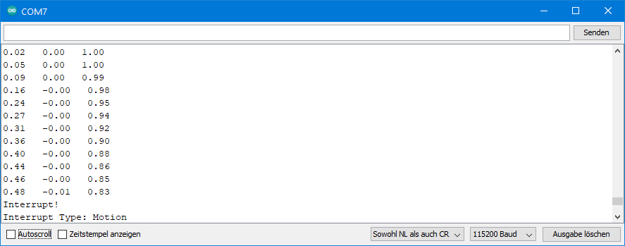
Ausgabe von ICM20948_10_wom_interrupt.ino
Für die folgende Ausgabe habe ich die x-Achse des ICM-20948 langsam aufgerichtet.
ICM20948_11_fsync_interrupt.ino
Hier wird der FSYNC Pin als Interruptpin eingerichtet, der wahlweise auf HIGH oder LOW auslöst. Ihr müsst, je nach Einstellung, einen Pull-Up oder Pull-Down Widerstand an FSYNC installieren. Im Gegensatz zu den anderen Interrupts wird der FSYNC-Interrupt nicht am Interruptpin ausgegeben. Ihr müsst den Status deshalb aktiv abfragen.
#include <Wire.h>
#include <ICM20948_WE.h>
#define ICM20948_ADDR 0x68

/* There are several ways to create your ICM20948 object:
 * ICM20948_WE myIMU = ICM20948_WE()              -> uses Wire / I2C Address = 0x68
 * ICM20948_WE myIMU = ICM20948_WE(ICM20948_ADDR) -> uses Wire / ICM20948_ADDR
 * ICM20948_WE myIMU = ICM20948_WE(&wire2)        -> uses the TwoWire object wire2 / ICM20948_ADDR
 * ICM20948_WE myIMU = ICM20948_WE(&wire2, ICM20948_ADDR) -> all together
 * ICM20948_WE myIMU = ICM20948_WE(CS_PIN, spi);  -> uses SPI, spi is just a flag, see SPI example
 * ICM20948_WE myIMU = ICM20948_WE(&SPI, CS_PIN, spi);  -> uses SPI / passes the SPI object, spi is just a flag, see SPI example
 */
ICM20948_WE myIMU = ICM20948_WE(ICM20948_ADDR);

const int intPin = 2;
volatile bool fsyncEvent = false;

void setup() {
  //delay(2000); // maybe needed for some MCUs, in particular for startup after power off
  Wire.begin();
  Serial.begin(115200);
  while(!Serial) {}

  if(!myIMU.init()){
    Serial.println("ICM20948 does not respond");
  }
  else{
    Serial.println("ICM20948 is connected");
  }

  /* Set the interrupt pin:
   * ICM20948_ACT_LOW  = active-low
   * ICM20948_ACT_HIGH = active-high (default)
   */
   //myIMU.setIntPinPolarity(ICM20948_ACT_LOW);

  /*  If latch is enabled the interrupt pin level is held until the interrupt status
   *  is cleared. If latch is disabled the interrupt pulse is ~50µs (default).
   */
   myIMU.enableIntLatch(true);

  /* The interrupts ICM20948_FSYNC_INT, ICM20948_WOM_INT and ICM20948_DMP_INT can be
   * cleared by any read or will only be cleared if the interrupt status register is
   * read (default).
   */
   //myIMU.enableClearIntByAnyRead(true);

  /* Set the FSync interrupt pin:
   *  ICM20948_ACT_LOW  = interrupt if low
   *  ICM20948_ACT_HIGH = interrupt if high (default)
   */
   //myIMU.setFSyncIntPolarity(ICM20948_ACT_LOW);

  /* The following interrupts can be enabled or disabled:
   *  ICM20948_FSYNC_INT        FSYNC pin interrupt, can't propagate to the INT pin
   *  ICM20948_WOM_INT          Wake on motion
   *  ICM20948_DATA_READY_INT   New data available
   *  ICM20948_FIFO_OVF_INT     FIFO overflow
   */
  myIMU.enableInterrupt(ICM20948_FSYNC_INT);
  //myIMU.disableInterrupt(ICM20948_DATA_READY_INT);

  Serial.println("Pull down the FSYNC pin with a 10kOhm resistor.");
  Serial.println("A HIGH signal to pin FSYNC will then cause an interrupt - try it!");
}

void loop() {
  byte source = myIMU.readAndClearInterrupts();
  if(myIMU.checkInterrupt(source, ICM20948_FSYNC_INT)){
    Serial.println("Interrupt! Type: FSync Pin Interrupt");
  }
}
Der Sketch verwendet nur eine neue Funktion, nämlich setFSyncIntPolarity(). Damit legt ihr fest, ob der Interrupt bei HIGH oder LOW auslöst.
FIFO Funktionen des ICM-20948
Der FIFO (first in, first out) Speicher ist eine Art Rekorder für Messdaten. Die Daten, die der ICM-20948 zuerst hineinschreibt, liest er auch zuerst aus – daher sein Name. Der FIFO hat laut Datenblatt eine Größe von 512 Bytes. Allerdings habe ich die DMP Funktion nicht implementiert. Dadurch wächst der FIFO auf komfortable 4096 Bytes.
Ihr bestimmt, welche Daten in den FIFO geschrieben werden. Damit legt ihr auch fest, wie viele Datensätze in den FIFO passen. Ein Beschleunigungs- oder Gyroskopwert benötigt zwei Bytes. Dabei werden immer die Rohdaten gespeichert. Ein x,y,z-Triple benötigt dementsprechend 6 Byte. Ich habe folgende Auswahloptionen implementiert:
- Beschleunigungswerte als vollständige Triple – 682 vollständige Triple passen (4096 / 6 = 682, Rest 4) in den FIFO.
- Gyroskopwerte als vollständige Triple – 682 vollständige Triple passen.
- Beschleunigungs- und Gyroskopwerte – 341 vollständige Datensätze möglich (4096 / 12 = 341, Rest 4).
- Der ICM-20948 kann darüber hinaus auch Gyroskopdaten einzelner Achsen, Temperaturen oder Daten externer Sensoren aufnehmen. Das habe ich allerdings nicht implementiert, sondern mich auf die o.a. Optionen beschränkt.
Zum Auslesen des FIFO Registers werden die FIFO Daten nacheinander in ein Datenregister mit einer Breite von einem Byte geschoben. Von dort liest man die Bytes einzeln aus und setzt sie wieder zu sinnvollen Daten zusammen. Allerdings ist den einzelnen Bytes sozusagen nicht anzusehen, ob es sich um das MSB oder LSB eines Beschleunigungs- oder Gyroskopwertes handelt. Man muss also mitzählen und in der richtigen Reihenfolge auslesen. Das lässt sich aber nur zu einem gewissen Grad automatisieren. Und um es für den Benutzer nicht zu komplex und damit fehleranfällig werden zu lassen, habe ich nicht alle Optionen implementiert.
ICM20948_12_FIFO_stop_when_full.ino
In diesem ersten FIFO Sketch stoppt der ICM-20948 die Datenaufnahme, wenn der FIFO voll ist. Das heißt, dass ihr den Startschuss gebt und die Aufnahmezeit von der Datenrate und den aufgenommenen Datentypen abhängt. Eine Kombination aus FIFO und dem Cycle Modus funktioniert übrigens nicht.
Wenn der FIFO voll ist, könnt ihr euch darüber mithilfe des FIFO Overflow Interrupts informieren lassen.
Bei Aufnahme von Beschleunigungs- und Gyroskopdaten schreibt der ICM-20948 immer zuerst die Beschleunigungsdaten in den FIFO. Da er in diesem Beispiel stoppt, wenn der FIFO voll ist, beginnt der FIFO mit einem Beschleunigungswert. Das ist wichtig für das korrekte Auslesen!
In meinem Beispielsketch nehme ich Daten für den Beschleunigungssensor und das Gyroskop auf. Die Datenrate des Gyroskopes hat Priorität. Der Sample Rate Divider ist auf 20 eingestellt. Damit ist die Datenrate 1125/20 = 56.25 Hz. Da 341 Datensätze aufgenommen werden, läuft der FIFO Puffer nach ca. 6 Sekunden über.
#include <Wire.h>
#include <ICM20948_WE.h>
#define ICM20948_ADDR 0x68

/* There are several ways to create your ICM20948 object:
 * ICM20948_WE myIMU = ICM20948_WE()              -> uses Wire / I2C Address = 0x68
 * ICM20948_WE myIMU = ICM20948_WE(ICM20948_ADDR) -> uses Wire / ICM20948_ADDR
 * ICM20948_WE myIMU = ICM20948_WE(&wire2)        -> uses the TwoWire object wire2 / ICM20948_ADDR
 * ICM20948_WE myIMU = ICM20948_WE(&wire2, ICM20948_ADDR) -> all together
 * ICM20948_WE myIMU = ICM20948_WE(CS_PIN, spi);  -> uses SPI, spi is just a flag, see SPI example
 * ICM20948_WE myIMU = ICM20948_WE(&SPI, CS_PIN, spi);  -> uses SPI / passes the SPI object, spi is just a flag, see SPI example
 */
ICM20948_WE myIMU = ICM20948_WE(ICM20948_ADDR);

const int intPin = 2;
volatile bool fifoFull = false;

void setup() {
  //delay(2000); // maybe needed for some MCUs, in particular for startup after power off
  Wire.begin();
  Serial.begin(115200);
  while(!Serial) {}

  if(!myIMU.init()){
    Serial.println("ICM20948 does not respond");
  }
  else{
    Serial.println("ICM20948 is connected");
  }

 //myIMU.setAccOffsets(-16330.0, 16450.0, -16600.0, 16180.0, -16520.0, 16690.0);

  /* The starting point, if you position the ICM20948 flat, is not necessarily 0g/0g/1g for x/y/z.
   * The autoOffset function measures offset. It assumes your ICM20948 is positioned flat with its
   * x,y-plane. The more you deviate from this, the less accurate will be your results.
   * It overwrites the zero points of setAccOffsets, but keeps the correction of the slope.
   * The function also measures the offset of the gyroscope data. The gyroscope offset does not
   * depend on the positioning.
   * This function needs to be called after setAccOffsets but before other settings since it will
   * overwrite settings!
   * You can query the offsets with the functions:
   * xyzFloat getAccOffsets() and xyzFloat getGyrOffsets()
   * You can apply the offsets using:
   * setAccOffsets(xyzFloat yourOffsets) and setGyrOffsets(xyzFloat yourOffsets)
   */
  Serial.println("Position your ICM20948 flat and don't move it - calibrating...");
  delay(1000);
  myIMU.autoOffsets();
  Serial.println("Done!");

  /*  The gyroscope data is not zero, even if you don't move the ICM20948.
   *  To start at zero, you can apply offset values. These are the gyroscope raw values you obtain
   *  using the +/- 250 degrees/s range.
   *  Use either autoOffset or setGyrOffsets, not both.
   */
  //myIMU.setGyrOffsets(-115.0, 130.0, 105.0);

  /* enables or disables the acceleration sensor, default: enabled */
  //myIMU.enableAcc(true);

  /*  ICM20948_ACC_RANGE_2G      2 g   (default)
   *  ICM20948_ACC_RANGE_4G      4 g
   *  ICM20948_ACC_RANGE_8G      8 g
   *  ICM20948_ACC_RANGE_16G    16 g
   */
  myIMU.setAccRange(ICM20948_ACC_RANGE_2G);

  /*  Choose a level for the Digital Low Pass Filter or switch it off.
   *  ICM20948_DLPF_0, ICM20948_DLPF_2, ...... ICM20948_DLPF_7, ICM20948_DLPF_OFF
   *
   *  IMPORTANT: This needs to be ICM20948_DLPF_7 if DLPF is used in cycle mode!
   *
   *  DLPF       3dB Bandwidth [Hz]      Output Rate [Hz]
   *    0              246.0               1125/(1+ASRD)
   *    1              246.0               1125/(1+ASRD)
   *    2              111.4               1125/(1+ASRD)
   *    3               50.4               1125/(1+ASRD)
   *    4               23.9               1125/(1+ASRD)
   *    5               11.5               1125/(1+ASRD)
   *    6                5.7               1125/(1+ASRD)
   *    7              473.0               1125/(1+ASRD)
   *    OFF           1209.0               4500
   *
   *    ASRD = Accelerometer Sample Rate Divider (0...4095)
   *    You achieve lowest noise using level 6
   */
  myIMU.setAccDLPF(ICM20948_DLPF_6);

  /*  Acceleration sample rate divider divides the output rate of the accelerometer.
   *  Sample rate = Basic sample rate / (1 + divider)
   *  It can only be applied if the corresponding DLPF is not off!
   *  Divider is a number 0...4095 (different range compared to gyroscope)
   *  If sample rates are set for the accelerometer and the gyroscope, the gyroscope
   *  sample rate has priority.
   */
  myIMU.setAccSampleRateDivider(20);

  /* enables or disables the gyroscope sensor, default: enabled */
  // myIMU.enableGyr(false);

  /*  ICM20948_GYRO_RANGE_250       250 degrees per second (default)
   *  ICM20948_GYRO_RANGE_500       500 degrees per second
   *  ICM20948_GYRO_RANGE_1000     1000 degrees per second
   *  ICM20948_GYRO_RANGE_2000     2000 degrees per second
   */
  myIMU.setGyrRange(ICM20948_GYRO_RANGE_250);

  /*  Choose a level for the Digital Low Pass Filter or switch it off.
   *  ICM20948_DLPF_0, ICM20948_DLPF_2, ...... ICM20948_DLPF_7, ICM20948_DLPF_OFF
   *
   *  DLPF       3dB Bandwidth [Hz]      Output Rate [Hz]
   *    0              196.6               1125/(1+GSRD)
   *    1              151.8               1125/(1+GSRD)
   *    2              119.5               1125/(1+GSRD)
   *    3               51.2               1125/(1+GSRD)
   *    4               23.9               1125/(1+GSRD)
   *    5               11.6               1125/(1+GSRD)
   *    6                5.7               1125/(1+GSRD)
   *    7              361.4               1125/(1+GSRD)
   *    OFF          12106.0               9000
   *
   *    GSRD = Gyroscope Sample Rate Divider (0...255)
   *    You achieve lowest noise using level 6
   */
  myIMU.setGyrDLPF(ICM20948_DLPF_6);

  /*  Gyroscope sample rate divider divides the output rate of the gyroscope.
   *  Sample rate = Basic sample rate / (1 + divider)
   *  It can only be applied if the corresponding DLPF is not OFF!
   *  Divider is a number 0...255
   *  If sample rates are set for the accelerometer and the gyroscope, the gyroscope
   *  sample rate has priority.
   */
  myIMU.setGyrSampleRateDivider(20);

  /*  Set the interrupt pin:
   *  ICM20948_ACT_LOW  = active-low
   *  ICM20948_ACT_HIGH = active-high (default)
   */
   //myIMU.setIntPinPolarity(ICM20948_ACT_LOW);

  /*  If latch is enabled the interrupt pin level is held until the interrupt status
   *  is cleared. If latch is disabled the interrupt pulse is ~50µs (default).
   */
  myIMU.enableIntLatch(true);

  /*  The interrupts ICM20948_FSYNC_INT, ICM20948_WOM_INT and ICM20948_DMP_INT can be
   *  cleared by any read or will only be cleared if the interrupt status register is
   *  read (default).
   */
  //myIMU.enableClearIntByAnyRead(true);

  /* The following interrupts can be enabled or disabled:
   *  ICM20948_FSYNC_INT        FSYNC pin interrupt, can't propagate to the INT pin
   *  ICM20948_WOM_INT          Wake on motion
   *  ICM20948_DATA_READY_INT   New data available
   *  ICM20948_FIFO_OVF_INT     FIFO overflow
   */
  myIMU.enableInterrupt(ICM20948_FIFO_OVF_INT);
  //myIMU.disableInterrupt(ICM20948_WOM_INT);

  /* enables the FIFO function, default: disabled */
  //myIMU.enableFifo(true);

  /* There are two different FIFO modes:
   *  ICM20948_CONTINUOUS --> samples are continuously stored in FIFO. If FIFO is full
   *  new data will replace the oldest.
   *  ICM20948_STOP_WHEN_FULL --> self-explaining
   */
  //myIMU.setFifoMode(ICM20948_STOP_WHEN_FULL); // used below, but explained here

  /* The argument of startFifo defines the data stored in the FIFO
   * ICM20948_FIFO_ACC --> Acceleration Data ist stored in FIFO
   * ICM20948_FIFO_GYR --> Gyroscope data is stored in FIFO
   * ICM20948_FIFO_ACC_GYR --> Acceleration and Gyroscope Data is stored in FIFO
   * The library does not (yet) support storing single gyroscope axes data, temperature
   * or data from slaves.
   */
  //myIMU.startFifo(ICM20948_FIFO_ACC); // used below, but explained here

  /* stopFifo():
   * - stops additional writes into Fifo
   * - clears the data type written into Fifo (acceleration and/or gyroscope
   */
  //myIMU.stopFifo();

  /* sets the Fifo counter to zero */
  //myIMU.resetFifo();


  attachInterrupt(digitalPinToInterrupt(intPin), eventISR, RISING);
  myIMU.setFifoMode(ICM20948_STOP_WHEN_FULL);
  myIMU.enableFifo(true);
  delay(100); // in some cases a delay after enabling Fifo makes sense
}

void loop() {
  countDown();
  myIMU.readAndClearInterrupts();
  fifoFull = false;
  myIMU.startFifo(ICM20948_FIFO_ACC_GYR);
  while(!fifoFull){}
  myIMU.stopFifo();
  printFifo();
  myIMU.resetFifo();

  Serial.println("For another series of measurements, enter any key and send");

  while(!(Serial.available())){}
  Serial.read();
  Serial.println();
 }

void printFifo(){
  int count = myIMU.getFifoCount();
  int dataSets = myIMU.getNumberOfFifoDataSets();
  Serial.print("Bytes in Fifo: ");
  Serial.println(count);
  Serial.print("Data Sets: ");
  Serial.println(dataSets);

  for(int i=0; i<dataSets; i++){
    xyzFloat gValue;
    xyzFloat gyr;
    myIMU.getGValuesFromFifo(&gValue);
    myIMU.getGyrValuesFromFifo(&gyr);
    Serial.print("Data set ");
    Serial.print(i+1);
    Serial.println(":");

    Serial.print(gValue.x);
    Serial.print("   ");
    Serial.print(gValue.y);
    Serial.print("   ");
    Serial.println(gValue.z);

    Serial.print(gyr.x);
    Serial.print("   ");
    Serial.print(gyr.y);
    Serial.print("   ");
    Serial.println(gyr.z);
  }
}

void countDown(){
  Serial.println("Move/turn your ICM20948 to obtain interesting data");
  Serial.println();
  delay(1000);
  Serial.print("Fifo collection begins in 3, ");
  delay(1000);
  Serial.print("2, ");
  delay(1000);
  Serial.print("1, ");
  delay(1000);
  Serial.println("Now!");
}

void eventISR() {
  fifoFull = true;
}
In meinem Beispiel startet ein Countdown den FIFO. Ihr könnt aber auch andere Auslöser wählen, z.B. einen WOM Interrupt.
Ist der FIFO voll, wird das durch einen Interrupt angezeigt. Dann erfolgt das Auslesen und die Ausgabe der Daten. Danach könnt ihr durch Senden eines Zeichens über den seriellen Monitor eine erneute FIFO Aufnahme starten.
Neue Funktionen
Folgende neue Funktionen kommen zum Einsatz:
enableFifo()aktiviert oder deaktiviert den FIFO.- Mit
setFifoMode()legt ihr fest, ob ihr den kontinuierlichen oder den „stop-when-full“ Modus einsetzt. - Ihr übergebt
startFiFo()die aufzunehmenden Datentypen. Mit dieser Funktion wird auch der Zähler gestartet. - Mit
stopFifo()verhindert ihr, dass weitere Messwerte in den FIFO geschoben werden. Dieser Vorgang ist zwar sowieso gestoppt, wenn der FIFO voll ist, allerdings nur vorerst. Wenn ihr mit dem Auslesen beginnt, wird wieder Platz geschaffen. Und der würde ohnestopFifo()sofort mit neuen Werten gefüllt. getFifoCount()liefert euch den FIFO Zählerstand in Bytes. Wenn der FIFO voll ist, sind das 4096. Aber ihr könntet theoretisch auch abbrechen, bevor der FIFO voll ist.getNumberOfFifoDataSets()berechnet die Anzahl von Datensätzen im FIFO. In diesem Beispiel besteht ein Datensatz aus einem x,y,z-Tripel Beschleunigungsdaten und einem x,y,z-Tripel Gyroskopdaten, also 12 Bytes.getGValuesFromFifo()liest ein x,y,z-Tripel Beschleunigungsdaten aus und rechnet dieses in ein g-Wertetripel um. Da der FIFO Rohdaten enthält, dürft ihr zwischen Aufnahme und Auslesen nicht die Parameter ändern (also z.B. Range oder Offsets).getGyrValuesFromFifo()liest ein x,y,z-Tripel Gyroskopdaten (Rohdaten) aus und rechnet dieses in Rotationswerte (°/s) um.resetFifo()setzt den FIFO Zähler auf null.
Ich möchte noch einmal betonen, dass ihr beim Auslesen die Reihenfolge einhalten müsst. In diesem Beispiel lest ihr Beschleunigungsdaten und Gyroskopdaten im Wechsel und beginnt mit den Beschleunigungsdaten.
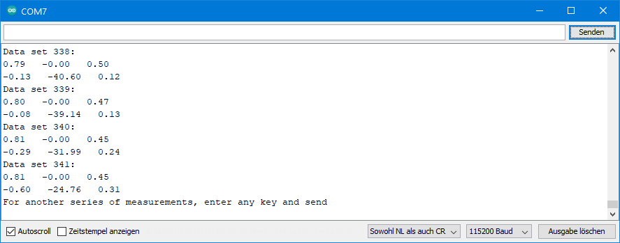
Ausgabe von ICM20949_12_FIFO_stop_when_full.ino
So sieht dann ein Ausschnitt der Ausgabe aus:
ICM20948_13_FIFO_continuous.ino
Bei dieser Methode nimmt der FIFO kontinuierlich die von euch festgelegten Datentypen auf. Hier legt ihr also nicht den Start, sondern das Ende fest. Wenn der FIFO voll ist, bevor ihr stoppt, schmeißt er die ältesten Daten zugunsten der neuen Daten raus.
Der ICM-20948 schreibt immer vollständige Datensätze in den FIFO. Das bedeutet, ihr habt ein definiertes Ende. Der Anfang hingegen befindet sich irgendwo in einem Datensatz. Das liegt daran, der FIFO keine vollständigen Datensätze hinausschmeißt. Bei 4096 Bytes wird brutal gekappt. Deswegen gibt es hier eine zusätzliche Funktion, die beim Auslesen den Anfang des ersten vollständigen Datensatzes findet.
Der Beispielsketch benutzt einen WOM Interrupt als Stopp-Signal für den FIFO. Dreht den ICM-20948, um den Interrupt auszulösen. Hier habe ich den Sample Rate Divider auf 10 eingestellt. Daraus ergibt sich eine Datenrate von 1125 / 11 = ~100 Hz. Das heißt, der FIFO enthält unter diesen Bedingungen die Daten der letzten 3.4 Sekunden.
#include <Wire.h>
#include <ICM20948_WE.h>
#define ICM20948_ADDR 0x68

/* There are several ways to create your ICM20948 object:
 * ICM20948_WE myIMU = ICM20948_WE()              -> uses Wire / I2C Address = 0x68
 * ICM20948_WE myIMU = ICM20948_WE(ICM20948_ADDR) -> uses Wire / ICM20948_ADDR
 * ICM20948_WE myIMU = ICM20948_WE(&wire2)        -> uses the TwoWire object wire2 / ICM20948_ADDR
 * ICM20948_WE myIMU = ICM20948_WE(&wire2, ICM20948_ADDR) -> all together
 * ICM20948_WE myIMU = ICM20948_WE(CS_PIN, spi);  -> uses SPI, spi is just a flag, see SPI example
 * ICM20948_WE myIMU = ICM20948_WE(&SPI, CS_PIN, spi);  -> uses SPI / passes the SPI object, spi is just a flag, see SPI example
 */
ICM20948_WE myIMU = ICM20948_WE(ICM20948_ADDR);

const int intPin = 2;
volatile bool womEvent = false;

void setup() {
  //delay(2000); // maybe needed for some MCUs, in particular for startup after power off
  Wire.begin();
  Serial.begin(115200);
  while(!Serial) {}

  if(!myIMU.init()){
    Serial.println("ICM20948 does not respond");
  }
  else{
    Serial.println("ICM20948 is connected");
  }

  /*  This is a method to calibrate. You have to determine the minimum and maximum
   *  raw acceleration values of the axes determined in the range +/- 2 g.
   *  You call the function as follows: setAccOffsets(xMin,xMax,yMin,yMax,zMin,zMax);
   *  The parameters are floats.
   *  The calibration changes the slope / ratio of raw acceleration vs g. The zero point is
   *  set as (min + max)/2.
   */
  //myIMU.setAccOffsets(-16330.0, 16450.0, -16600.0, 16180.0, -16520.0, 16690.0);

  /* The starting point, if you position the ICM20948 flat, is not necessarily 0g/0g/1g for x/y/z.
   * The autoOffset function measures offset. It assumes your ICM20948 is positioned flat with its
   * x,y-plane. The more you deviate from this, the less accurate will be your results.
   * It overwrites the zero points of setAccOffsets, but keeps the correction of the slope.
   * The function also measures the offset of the gyroscope data. The gyroscope offset does not
   * depend on the positioning.
   * This function needs to be called after setAccOffsets but before other settings since it will
   * overwrite settings!
   * You can query the offsets with the functions:
   * xyzFloat getAccOffsets() and xyzFloat getGyrOffsets()
   * You can apply the offsets using:
   * setAccOffsets(xyzFloat yourOffsets) and setGyrOffsets(xyzFloat yourOffsets)
   */
  Serial.println("Position your ICM20948 flat and don't move it - calibrating...");
  delay(1000);
  myIMU.autoOffsets();
  Serial.println("Done!");

  /*  The gyroscope data is not zero, even if you don't move the ICM20948.
   *  To start at zero, you can apply offset values. These are the gyroscope raw values you obtain
   *  using the +/- 250 degrees/s range.
   *  Use either autoOffset or setGyrOffsets, not both.
   */
  //myIMU.setGyrOffsets(-115.0, 130.0, 105.0);

  /* enables or disables the acceleration sensor, default: enabled */
  // myIMU.enableAcc(true);

  /*  ICM20948_ACC_RANGE_2G      2 g   (default)
   *  ICM20948_ACC_RANGE_4G      4 g
   *  ICM20948_ACC_RANGE_8G      8 g
   *  ICM20948_ACC_RANGE_16G    16 g
   */
  myIMU.setAccRange(ICM20948_ACC_RANGE_2G);

  /*  Choose a level for the Digital Low Pass Filter or switch it off.
   *  ICM20948_DLPF_0, ICM20948_DLPF_2, ...... ICM20948_DLPF_7, ICM20948_DLPF_OFF
   *
   *  IMPORTANT: This needs to be ICM20948_DLPF_7 if DLPF is used in cycle mode!
   *
   *  DLPF       3dB Bandwidth [Hz]      Output Rate [Hz]
   *    0              246.0               1125/(1+ASRD)
   *    1              246.0               1125/(1+ASRD)
   *    2              111.4               1125/(1+ASRD)
   *    3               50.4               1125/(1+ASRD)
   *    4               23.9               1125/(1+ASRD)
   *    5               11.5               1125/(1+ASRD)
   *    6                5.7               1125/(1+ASRD)
   *    7              473.0               1125/(1+ASRD)
   *    OFF           1209.0               4500
   *
   *    ASRD = Accelerometer Sample Rate Divider (0...4095)
   *    You achieve lowest noise using level 6
   */
  myIMU.setAccDLPF(ICM20948_DLPF_6);

  /*  Acceleration sample rate divider divides the output rate of the accelerometer.
   *  Sample rate = Basic sample rate / (1 + divider)
   *  It can only be applied if the corresponding DLPF is not off!
   *  Divider is a number 0...4095 (different range compared to gyroscope)
   *  If sample rates are set for the accelerometer and the gyroscope, the gyroscope
   *  sample rate has priority.
   */
  myIMU.setAccSampleRateDivider(10);

  /* enables or disables the gyroscope sensor, default: enabled */
  // myIMU.enableGyr(false);

  /*  ICM20948_GYRO_RANGE_250       250 degrees per second (default)
   *  ICM20948_GYRO_RANGE_500       500 degrees per second
   *  ICM20948_GYRO_RANGE_1000     1000 degrees per second
   *  ICM20948_GYRO_RANGE_2000     2000 degrees per second
   */
  //myIMU.setGyrRange(ICM20948_GYRO_RANGE_250);

  /*  Choose a level for the Digital Low Pass Filter or switch it off.
   *  ICM20948_DLPF_0, ICM20948_DLPF_2, ...... ICM20948_DLPF_7, ICM20948_DLPF_OFF
   *
   *  DLPF       3dB Bandwidth [Hz]      Output Rate [Hz]
   *    0              196.6               1125/(1+GSRD)
   *    1              151.8               1125/(1+GSRD)
   *    2              119.5               1125/(1+GSRD)
   *    3               51.2               1125/(1+GSRD)
   *    4               23.9               1125/(1+GSRD)
   *    5               11.6               1125/(1+GSRD)
   *    6                5.7               1125/(1+GSRD)
   *    7              361.4               1125/(1+GSRD)
   *    OFF          12106.0               9000
   *
   *    GSRD = Gyroscope Sample Rate Divider (0...255)
   *    You achieve lowest noise using level 6
   */
  myIMU.setGyrDLPF(ICM20948_DLPF_6);

  /*  Gyroscope sample rate divider divides the output rate of the gyroscope.
   *  Sample rate = Basic sample rate / (1 + divider)
   *  It can only be applied if the corresponding DLPF is not OFF!
   *  Divider is a number 0...255
   *  If sample rates are set for the accelerometer and the gyroscope, the gyroscope
   *  sample rate has priority.
   */
  myIMU.setGyrSampleRateDivider(10);

  /*  Set the interrupt pin:
   *  ICM20948_ACT_LOW  = active-low
   *  ICM20948_ACT_HIGH = active-high (default)
   */
  //myIMU.setIntPinPolarity(ICM20948_ACT_LOW);

  /*  If latch is enabled the interrupt pin level is held until the interrupt status
   *  is cleared. If latch is disabled the interrupt pulse is ~50µs (default).
   */
  myIMU.enableIntLatch(true);

  /*  The interrupts ICM20948_FSYNC_INT, ICM20948_WOM_INT and ICM20948_DMP_INT can be
   *  cleared by any read or will only be cleared if the interrupt status register is
   *  read (default).
   */
  //myIMU.enableClearIntByAnyRead(true);

  /* The following interrupts can be enabled or disabled:
   *  ICM20948_FSYNC_INT        FSYNC pin interrupt, can't propagate to the INT pin
   *  ICM20948_WOM_INT          Wake on motion
   *  ICM20948_DATA_READY_INT   New data available
   *  ICM20948_FIFO_OVF_INT     FIFO overflow
   */
  myIMU.enableInterrupt(ICM20948_WOM_INT);
  //myIMU.disableInterrupt(ICM20948_WOM_INT);

  /* setWakeOnMotionThreshold sets the limit (first argument) for a wake on
   * motion interrupt and defines the WOM mode (second argument). The limit
   * is a number between 1 and 255 with 1 = 4 mg (milli-g) and 255 = 1020 mg.
   * You can choose from two modes:
   * ICM20948_WOM_COMP_DISABLE = compare the sample with the initial sample (default).
   * ICM20948_WOM_COMP_ENABLE = compare the sampe with the previous sample.
   */
  myIMU.setWakeOnMotionThreshold(128, ICM20948_WOM_COMP_DISABLE);

  /* enables the FIFO function, default: disabled */
  // myIMU.enableFifo(true); // explained here, used below

  /* There are two different FIFO modes:
   *  ICM20948_CONTINUOUS --> samples are continuously stored in FIFO. If FIFO is full
   *  new data will replace the oldest.
   *  ICM20948_STOP_WHEN_FULL --> self-explaining
   */
  //myIMU.setFifoMode(ICM20948_STOP_WHEN_FULL); // used below, but explained here

  /* The argument of startFifo defines the data stored in the FIFO
   * ICM20948_FIFO_ACC --> Acceleration Data ist stored in FIFO
   * ICM20948_FIFO_GYR --> Gyroscope data is stored in FIFO
   * ICM20948_FIFO_ACC_GYR --> Acceleration and Gyroscope Data is stored in FIFO
   * The library does not (yet) support storing single gyroscope axes data, temperature
   * or data from slaves.
   */
  //myIMU.startFifo(ICM20948_FIFO_ACC); // used below, but explained here

  /* stopFifo():
   * - stops additional writes into Fifo
   * - clears the data type written into Fifo (acceleration and/or gyroscope)
   */
  //myIMU.stopFifo(); // explained here, used below

  /* sets the Fifo counter to zero */
  //myIMU.resetFifo(); // explained here, used below

  attachInterrupt(digitalPinToInterrupt(intPin), eventISR, RISING);
  myIMU.readAndClearInterrupts();
  womEvent = false;
  myIMU.setFifoMode(ICM20948_CONTINUOUS);
  myIMU.enableFifo(true);
  delay(100); // in some cases a delay after enabling Fifo makes sense
  myIMU.startFifo(ICM20948_FIFO_ACC_GYR);
  Serial.println("Turn your ICM20948 around the x or y axis.");
  Serial.println("Waiting for wake-on-motion event...");
}

void loop() {
  if(womEvent){
    myIMU.stopFifo();
    printFifo();
    myIMU.resetFifo();
    myIMU.startFifo(ICM20948_FIFO_ACC_GYR);

    Serial.println("For another series of measurements, enter any key and send");

    while(!(Serial.available())){}
    Serial.read();
    Serial.println();
    myIMU.readAndClearInterrupts();
    womEvent = false;
  }
}

void printFifo(){
  myIMU.findFifoBegin(); /* this is needed for continuous Fifo mode. The Fifo buffer ends with a
  complete data set, but it starts is within a data set. */
  int count = myIMU.getFifoCount();
  int dataSets = myIMU.getNumberOfFifoDataSets();
  Serial.print("Bytes in Fifo: ");
  Serial.println(count);
  Serial.print("Data Sets: ");
  Serial.println(dataSets);

  for(int i=0; i<dataSets; i++){
    /* if you read acceleration (g) and gyroscope values you need to start with g values */
    xyzFloat gValue;
    xyzFloat gyr;
    myIMU.getGValuesFromFifo(&gValue);
    myIMU.getGyrValuesFromFifo(&gyr);
    Serial.print("Data set ");
    Serial.print(i+1);
    Serial.println(":");

    Serial.print(gValue.x);
    Serial.print("   ");
    Serial.print(gValue.y);
    Serial.print("   ");
    Serial.println(gValue.z);

    Serial.print(gyr.x);
    Serial.print("   ");
    Serial.print(gyr.y);
    Serial.print("   ");
    Serial.println(gyr.z);
  }
}

void eventISR() {
  womEvent = true;
}
Der Sketch verwendet nur eine neue Funktion, und zwar ist das findFifoBegin(). Sie berechnet, wo der erste vollständige Datensatz beginnt. Dann liest sie die Daten bis zu diesem Beginn und verwirft sie. Deshalb gibt getFifoCount() nach Aufruf von findFifoBegin() keine 4096 zurück. Ihr könntet mal ausprobieren, getFifoCount() vor findFifoBegin() aufzurufen.
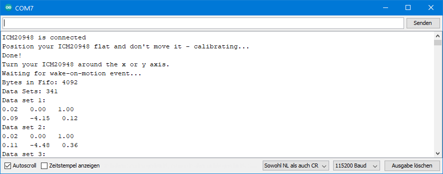
Ausgabe von ICM20948_13_FIFO_continuous.ino
So sieht ein Ausschnitt der Ausgabe auf dem seriellen Monitor aus (hier mal der Anfang):
Wenn ihr Lust habt, spielt ein wenig mit den FIFO Parametern herum. Wählt z.B. mal einen anderen Sample Rate Divider, ein anderes Stopp-Ereignis oder lasst den FIFO mal nicht volllaufen. Im letzteren Fall werdet ihr sehen, dass das Auslesen trotzdem klappt. Oder probiert mal aus, nur Beschleunigungs- oder Gyroskopdaten aufzunehmen.
ICM20948_14_blank_all_settings
Das ist kein fertiger Sketch, der irgendetwas Besonderes macht. Hier habe ich alle Funktionen aufgeführt, mit denen ihr Einstellungen vornehmt. Ich dachte mir, das könnte vielleicht eine gute Grundlage für eigene Sketche sein.
Toll, solche Beiträge geniessen ein ausgesprochenes Alleinstellungsmerkmal…
Herzlichen Dank, freut mich!
Hallo Wolfgang,
finde ich toll, dass jemand so ausführliche und verständliche Tutorials zur Verfügung stellt !!
Wie kann man dir, als kleine Anerkennung eine Spende zukommen lassen ?
Hallo Andreas,
Vielen Dank für das Angebot! Mein Lohn ist positives Feedback. Das freut mich immer sehr. Oder ein Stern für meine Bibliothek auf GitHub (da muss man sich allerdings für anmelden). Oder du lädst mich auf einen schönen Grünen Veltliner ein, falls ich mal in Österreich bin 😉 . VG, Wolfgang
Bun wieder begeistert, den Sensor habe ich schon….nur keine Zeit.
Vielen Dank
Ich danke – und das mit der Zeit kenne ich. Es soll ja Leute geben, die manchmal Langeweile haben. Mein Tag könnte gerne 12 Stunden länger sein und ich hätte trotzdem keine!