About this post
In this article, I would like to present various options for voltage regulation. Above all, it is about how you can provide defined voltages with given electrical supply sources. In detail, I will discuss the following topics:
Supply voltage from or via boards
Anyone who enters the world of microcontrollers via Arduino boards will use their existing, convenient infrastructure, especially at the beginning. The power for the board is supplied via the USB interface. For the supply of other elements, such as sensors or LEDs there is a 3.3 and a 5 volts output. The latter is at least the case for the AVR-based Arduino boards.
The voltage regulators used on the boards also allow operation with supply voltages between 7 and 12 volts. To do this, one uses the “VIN” pin or, e.g. on the Arduino UNO, the power supply socket.
So far, so convenient. However, at the latest, if you
- want to use the bare microcontroller (as in this article about the ATmega328P or in this one about ATtinys), or
- you need more power than the board can deliver (we’ll get to how much that is in a moment),
you need to think again about the appropriate power supply.
Supply voltage with linear voltage regulators
Linear voltage regulators (short: linear regulators) are DC/DC converters that typically provide voltages between 3 and 24 volts. The linear regulator compares the output voltage with a reference value. If the output voltage deviates, it is amplified accordingly. A distinction is made between fixed linear regulators, which output a fixed voltage value and adjustable linear regulators.
For most linear regulators, the input voltage must be 2 to 3 volts above the desired output voltage.
Efficiency of linear voltage regulators
In a linear regulator, the input current I is equal to the output current. Only the voltage U changes. For performance P, this means:
![\[ P_{in}=U_{in}\cdot I\;\;\;\text{and}\;\;\; P_{out} = U_{out}\cdot I \]](https://wolles-elektronikkiste.de/wp-content/ql-cache/quicklatex.com-7a884cbadf5b6cc97bc44f04a81dac86_l3.png "Rendered by QuickLaTeX.com")
![\[ P_{dissipation} = P_{in} - P_{out}=(U_{in}-U_{out})\cdot I \]](https://wolles-elektronikkiste.de/wp-content/ql-cache/quicklatex.com-dffbdbd078adace814a79241fcee173d_l3.png "Rendered by QuickLaTeX.com")
For the efficiency η:
![\[ \eta=\frac{U_{out}}{U_{in}}\cdot100\% \]](https://wolles-elektronikkiste.de/wp-content/ql-cache/quicklatex.com-756e2f4f38bd8aadc869f02df30d0b23_l3.png "Rendered by QuickLaTeX.com")
In other words, the greater the voltage difference, the worse the efficiency. And since the power dissipation is converted into heat, it may be necessary to provide the voltage regulator with a heat sink.
With a transformer, it’s different. There, the current also changes, so that the product of U and I remains constant. At least this applies to the ideal transformer.
How much power can Arduino UNO, Nano and Pro Mini supply at the 5 V pin?
The question was still open. When powered by USB, the limit is about 500 milliamperes, which is due to the USB interface and not to the Arduino. When powered by VIN or the current socket, the power dissipation of the voltage converter on the board is the limiting factor. 1 watt should not be exceeded. This means, for example, with 9 volt power supply:
![\[ 1000\, [\text{mW}]=(9\,[\text{V}]-5\,[\text{V}])\cdot I_{max}\,[\text{mA}] \]](https://wolles-elektronikkiste.de/wp-content/ql-cache/quicklatex.com-9d00ebbe83c8b93578814041e14fa46c_l3.png "Rendered by QuickLaTeX.com")
![\[ I_{max}=\frac{1000}{4}=250\,[\text{mA}] \]](https://wolles-elektronikkiste.de/wp-content/ql-cache/quicklatex.com-baf58e477b146b4bb0451a6a7ba010b4_l3.png "Rendered by QuickLaTeX.com")
Power supply with the L78xx series
The L78xx series is probably the most well-known series of fixed linear regulators. You can also sometimes find them under the name LM78xx, MC78xx or similar. “xx” stands for the output voltage, which is typically 5, 6, 8, 9, 12, 15, 18 or 24 volts. An L7805 thus provides 5 volts, an L7824 provides 24 volts.
The representatives of the L78xx series usually deliver 1 to 1.5 amperes. The L78Sxx series delivers currents up to 2 amperes. In addition, there is also the L78Mxx series for currents up to 500 mA and the L78Lxx series up to 100 mA.
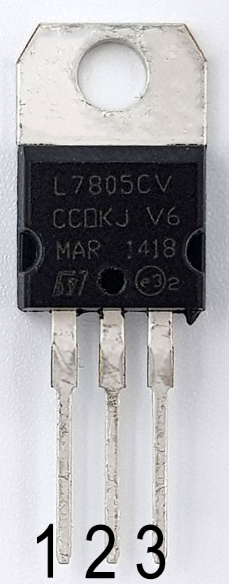
L78xx voltage regulators are available in various designs, such as the TO-220 model shown here. Pin 1 is the input, pin 2 is GND and pin 3 is output. You can find a data sheet for the L78xx series here.
Wiring the L78xx voltage regulators
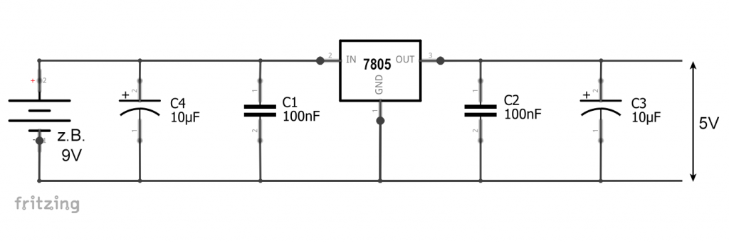
Wiring the L78xx voltage regulators is easy. You only need a few capacitors. Depending on the type of voltage source and the load, different sizes are recommended. Very often you will find the combination of 330 nF and 100 nF.

To make the circuit even more robust against fluctuations, you can add larger capacitors:
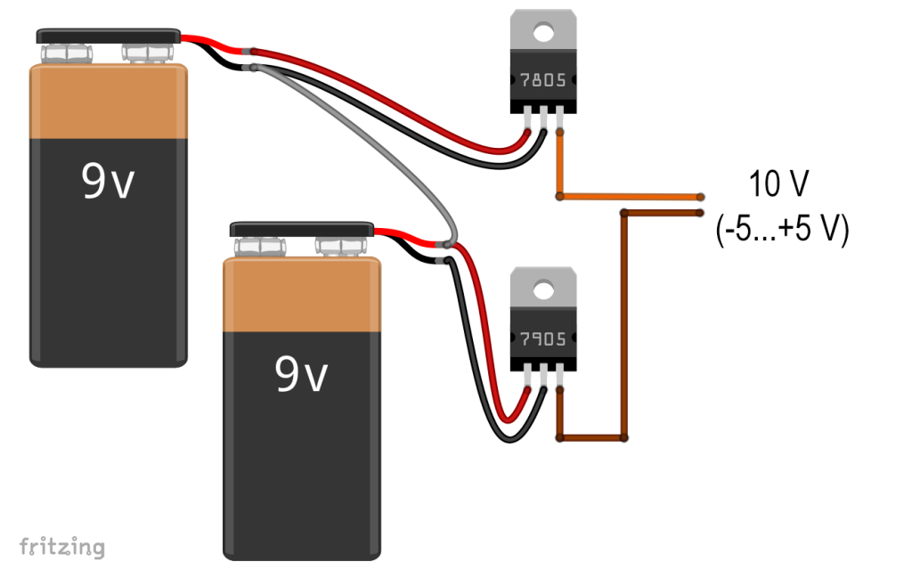
Symmetrical power supply with L78xx and L79xx
For some applications, such as certain operational amplifier circuits, you need a symmetrical power supply. For providing the negative voltage, you can select the L79xx series. For example, to generate +/-5 volts, you could use the following circuit (I omitted the capacitors for clarity!):
Other fixed linear fixed voltage regulators
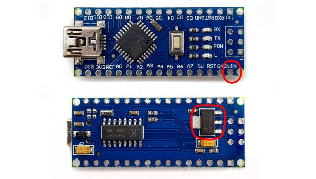
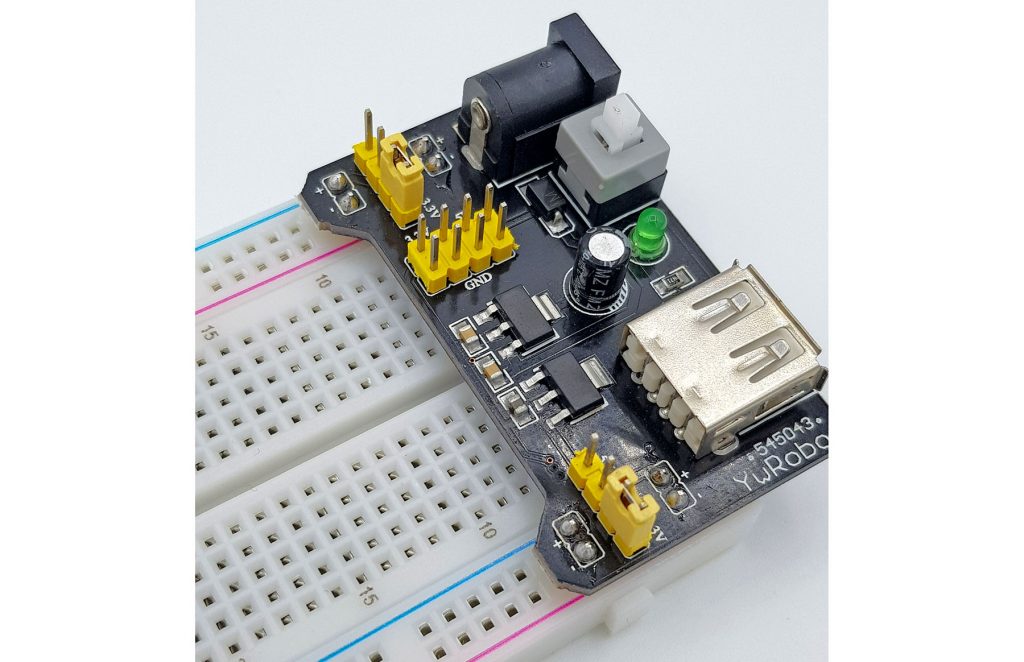
The L78xx series is certainly the most popular, but there are numerous other fixed voltage regulators. The Arduino Nano shown above uses the AMS1117-5.0 (data sheet here), which – as the name suggests – delivers 5 volts. A combination of an AMS1117-5.0 and an AMS1117-3.3 is used on these useful breadboard adapters:
If it is a problem for you that the input voltage of most linear regulators must be about 2.5 volts higher than the output voltage, you can resort to low dropout voltage regulators (LDO). For these, the minimum voltage difference is one volt or less. By the way, the AMS1117 is also an LDO and therefore well suited if you have to supply individual components with 3.3 volts in a 5 volt project.
If the 2 amperes of the L78Sxx series are not enough, you can switch to more powerful types such as the LT108x series. The LT1083, for example, can provide up to 7.5 amperes.
However, the more special the wishes are, the faster the price rises. If the L7805 is still available for 20 to 30 cents, you have to pay an incredible 10 to 20 Euros for an LT1083CP.
Power supply with the LM317
The classic among the adjustable linear voltage regulators is the LM317. With it, you can generate voltages between 1.25 and 37 volts. The input voltage must be at least three volts higher than the output voltage. The maximum current is specified as at least 1.5 amps (see data sheet).
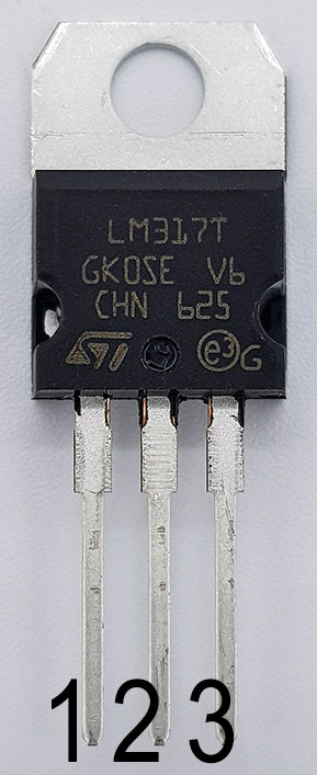
The LM317 has the three pins Adjust (1), Output (2) and Input (3).
The TO-220 design is shown here, but the LM317 is also available as an SMD.
Wiring the LM317
The output voltage of the LM317 is adjusted by two resistors. Here, for example, a circuit that generates 5 volts:
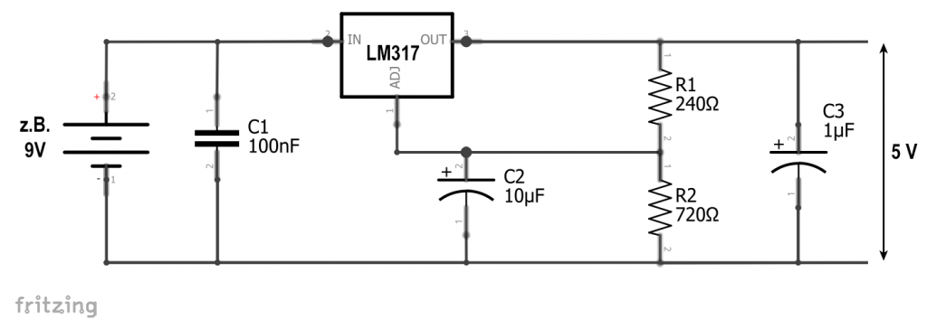
The LM317 sets a fixed voltage of 1.25 volts between OUT and ADJ, which drops across R1. The resistors R1 and R2 serve as a voltage divider across which the output voltage Uout drops. Therefore:
![\[ \frac{U_A}{R_1+R_2}=\frac{1,25}{R_1} \]](https://wolles-elektronikkiste.de/wp-content/ql-cache/quicklatex.com-422c344d12a9c45bc2cdc363aa95935e_l3.png "Rendered by QuickLaTeX.com")
![\[ U_A=1.25\cdot \frac{R_1+R_2}{R_1}=1.25\cdot \left( 1+\frac{R_2}{R_1}\right) \]](https://wolles-elektronikkiste.de/wp-content/ql-cache/quicklatex.com-e0b23df04e9bee9d4406b7bc93dcfc61_l3.png "Rendered by QuickLaTeX.com")
A resistance value of 240 ohms is recommended for R1.
If you use an adjustable resistor as R2, then you are flexible in terms of output voltage. However, make sure that you do not damage anything just because the resistance may have just been unfavorable. Better measure the output voltage before connecting anything.
The capacitors selected in the circuit diagram follow the recommendations of the data sheet.
The LM317 as current limiter
I do not want to make this article too long. Therefore, here is only the hint without further explanations that you can also use the LM317 as a current limiter. If you follow this link, you will get a compact description, including an online calculator.
Quiescent current of linear voltage regulators
Unfortunately, the voltage regulators consume current even when no current is drawn from the output side. For the L7805 I measured 3 mA at an input voltage of 9 volts, with the LM317 it was even 5 mA. This may be a killer criterion battery-based projects.
Power supply with switching regulators
The major disadvantage of the linear voltage regulators is the potentially high power dissipation. Last but not least, this has led to the development of switching regulators that operate much more efficiently in comparison, especially with large differences from input to output voltage.
With the switching regulation technology, it is possible not only to decrease but also to increase the output voltage compared to the input voltage. Modules that decrease the input voltage are called step-down converters (“Tiefsetzsteller” in German). It is no surprise that the modules that increase the input voltage are called step-up converters (“Hochsetzsteller”).
Step-down converter
Principle
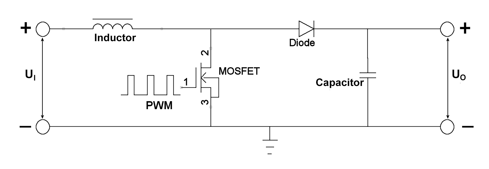
I will try to describe compactly in my words how a down converter works in principle (I hope it’s somehow understandable in my English). Here is a schematic:
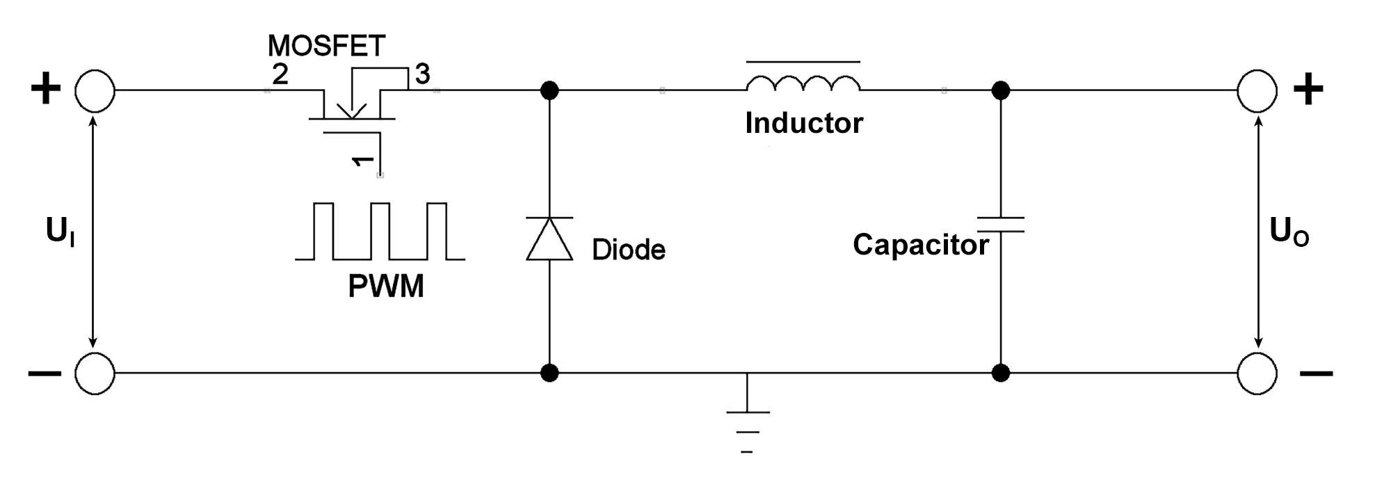
The mosfet is the controlling part in this scheme. It opens and closes at high frequency. The controlling parameter is the pulse width. If the mosfet is conductive (open), the diode locks and the current flows into the inductor. A magnetic field is induced, which counteracts the current flow. Current and voltage therefore increase at a reduced rate. If the mosfet is locked, the magnetic field in the inductor is degraded, inducing a current (a nice animation can be found here). The electricity wants to continue flowing, so to speak. The inductor draws the current and in this direction the diode is conductive, so that a circuit is formed via the diode, the inductor and the load at the output. In the interaction of inductor and capacitor, the current or voltage is smoothed.
The inductor is a kind of energy storage, which is filled only as much as it is needed on the output side. It is also important that the mosfet switches at high frequency. If it were to switch slowly, a triangle voltage would result on the output side, which would drop to zero again in between. Due to the high frequency and a controlled pulse width, the voltage is kept at an adjustable level. Nevertheless, the oscilloscope still shows a certain degree of triangle voltage (ripple). You will see this below with an example.
If you want to hear it explained again in different words without being bombarded with formulas, I recommend this YouTube video.
What about P = U x I?
In contrast to the linear voltage regulators, the output current is greater than the input current, since the current continues to flow even if the mosfet is blocked.
The voltage U decreases, but the current I increases and thus the power P remains constant. But of course there are losses here as well, but they are much smaller compared to the linear regulators.
An example, the LM2596
Below you see an LM2596 step-down module with a potentiometer for adjusting the output voltage. If you don’t want to deal with the calculation of the components (inductor, capacitor), such a module is a good solution.
The actual LM2596 is the IC with the 5 pins. It is available as version for fixed 3.3, 5 or 12 volts (LM2596xx), or adjustable as shown here.(LM2596-ADJ).
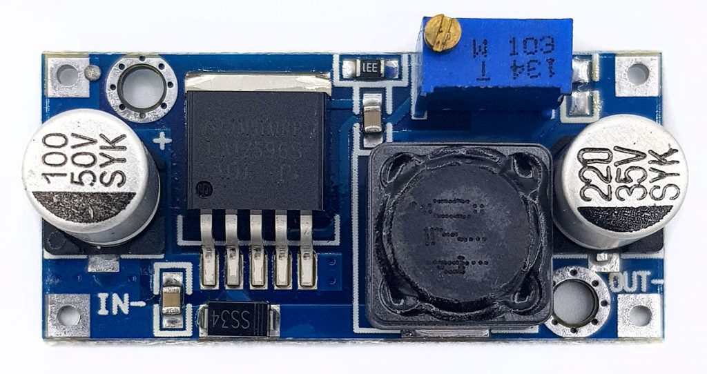
According to the supplier, this model can provide 4 to 34 volts and can be operated without heat sinks for up to 1 ampere. The input voltage should be at least 2 volts higher than the output voltage for the LM2596 to work efficiently. According to the supplier, the loss is a maximum of 8%.
The LM2596 IC itself would correspond to the mosfet with its control in the diagram shown above. Using a “feedback” pin, it checks the output voltage and adjusts the PWM signal accordingly. The clock of the LM2596 is 150 kHz, which corresponds to a period of 6.66 microseconds.
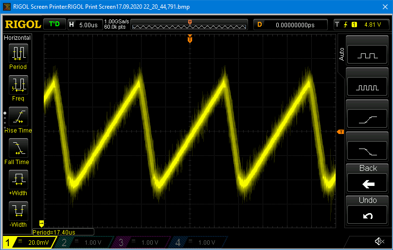
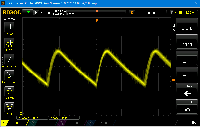
A few measurements on the LM2596 module
I set the LM2596 to 5 volts output and ran a light load (some LEDs). I then used the oscilloscope to look at the voltage signal. The characteristic fluctuation (“ripple”) was just over 60 mV. To my astonishment, however, the period (peak to peak) was rather close to 20 µs instead of the expected 6.6 µs, which corresponds to a frequency of 50 kHz. Whether an original LM2596 was actually installed here?

At higher load, it is interesting to see how the duty cycle of the PWM signal, i.e. the ratio of “on” or “high” to the period, increases. The ripple also rises, here to almost 100 mV. For most purposes, however, this will not be an issue.
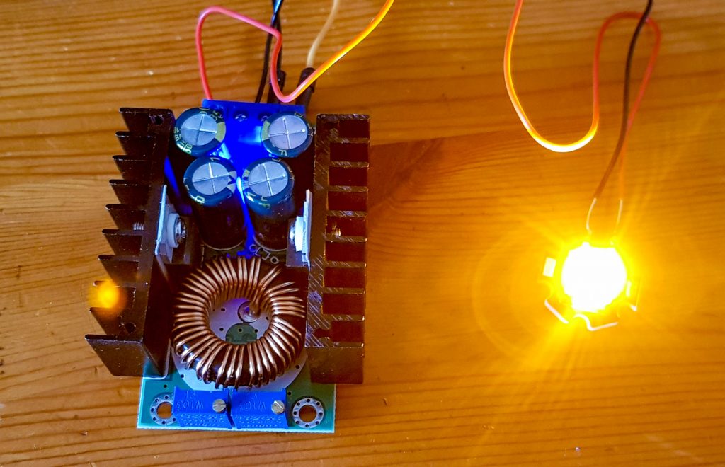
Step-down converter for high currents
If you need really high currents, e.g. 5 to 10 amps, then even the relatively low losses of the step-down converters will result in significant heat generation. In these cases you can use such “monsters” as shown below. By the way, you can find everything on Amazon or other online stores if you search for “step down converter”.
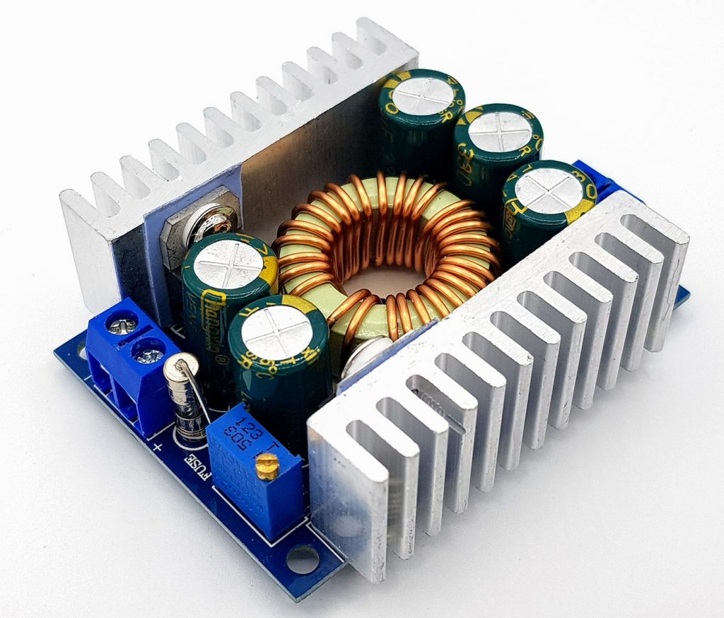
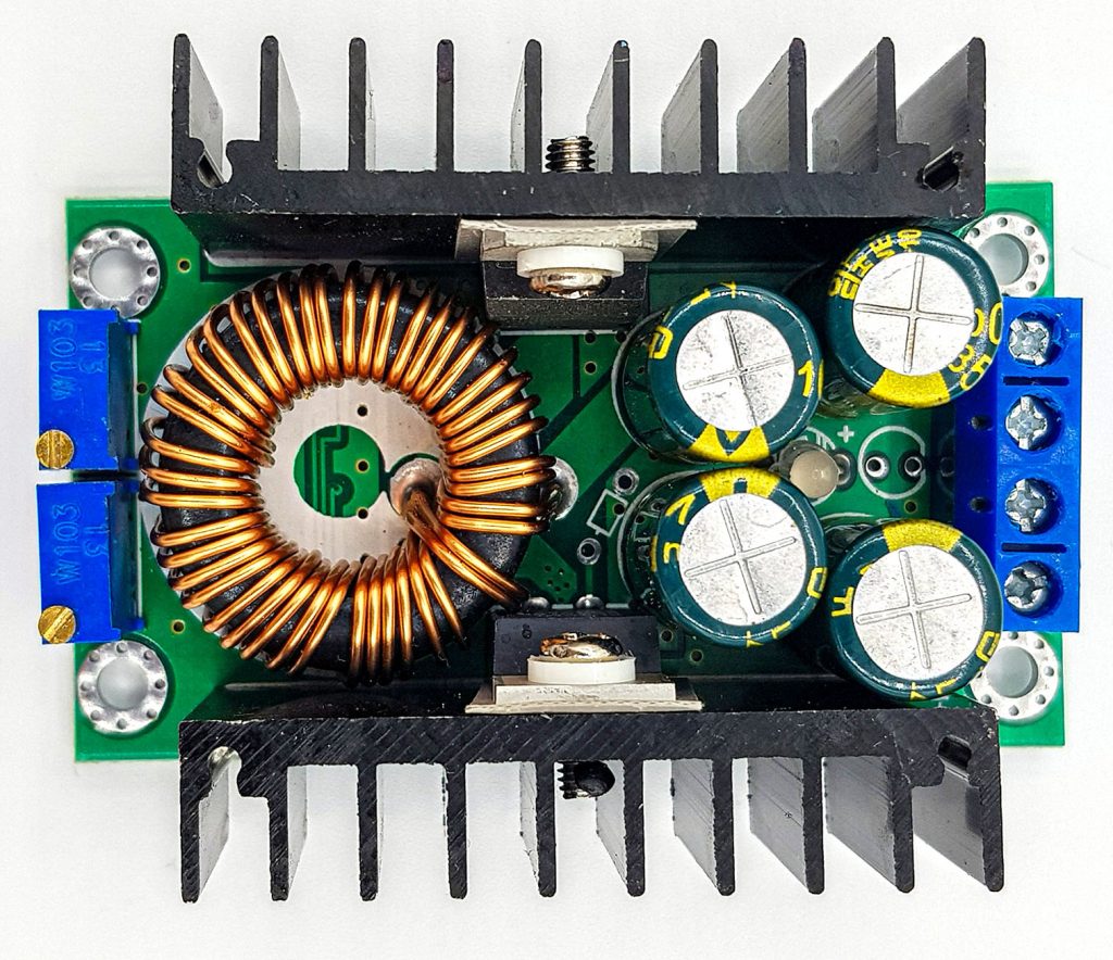
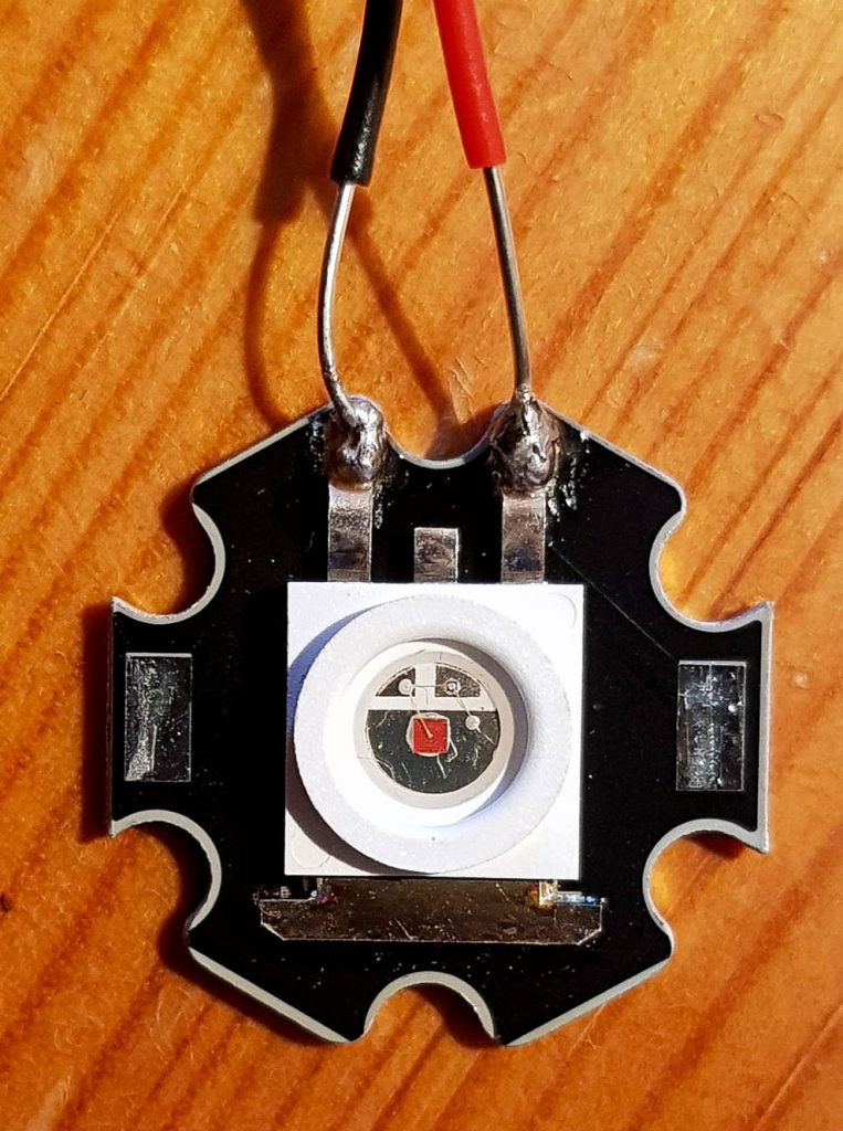
By the way, the converter on the top right is also interesting because you can set the output current in addition to the output voltage. This can then be used, for example, to operate power LEDs.
More compact switching regulators
You don’t necessarily have to buy switching controllers as a module. They are also available in a very compact design for various voltages and currents.
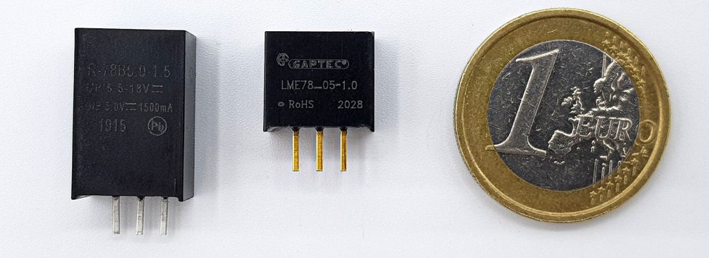
However, such parts are not entirely cheap. Up to 500 mA they are still available for less than 5 euros, for 1.5 or 2 amps 10 to 20 euros are due. Conrad has a well-structured range in this respect. Search for DC DC converters.
Quiescent current consumption of the step-down converters
The step-down converters, like the linear voltage regulators, also have a significant quiescent current consumption. For the LM2596 module, I measured a quiescent current of 7 mA at an input voltage of 9 volts and an output voltage of 5 volts.
The bare LM2596 IC has an on/off pin. In the off-state, the power consumption is in the microampere range. Unfortunately, the on/pff pin is not used on the module.
Step-up converter
A step-up converter consists of the same parts as a step-down converter, only the arrangement is different. And it may be a little harder to understand. Here again a schematic:
If the mosfet is open (conducting), UI drops completely across the inductor. The magnetic field that builds up and counteracts the current charges the inductor as a kind of energy storage. If the mosfet is closed, the inductor releases its energy. The current now flows through the diode and the consumer on the output side. Of course, the inductor charges even when the mosfet is locked. It is important to note that the inductor can store more energy when the Mosfet is open than when it is blocked, since in the latter case only part of UI falls across the inductor.
Examples
I have tested two step-up converter modules. One is based on an IC “E50D”. The other is based on the MT3608 IC. I only found a data sheet for the MT3608 IC (here the link).
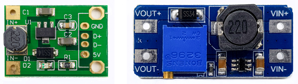
The E50D-based module delivers a fixed voltage of 5 volts. It is, for example, well suited to provide a voltage of 5 volts with a lithium battery (3.7 volts).
The MT3608 module provides adjustable output voltages up to 28 volts at input voltages from 2 to 24 volts. The maximum current is given as 2 amperes. I haven’t tried it, but I dare to doubt that it is actually possible to pull up a 2 volt power source to 28 volts and draw 2 amps at the same time with this module. Here you will certainly have to test how far you can really get. According to the supplier, the efficiency is 93%.
With the oscilloscope, I could see again the typical ripple (here on the E50D module):
Application: Operate a microcontroller with a steam engine
Still motivated? A bit I still have to report. To lighten the mood, let’s continue with an application that is not entirely serious. I borrowed my son’s steam engine and operated an ATtiny85, which in turn flashed 2 LEDs.
The generator at the steam engine supplies a rather fluctuating DC voltage, which also depends on the speed. I could reach a maximum of about 4 volts. With capacitors, I smoothed the voltage and then brought it to 5 volts with the step-up converter. Here is a video:
The power of esbit! The elders remember the fishy-smelling dry fuel. By the way: already knew what Itbit means? “Erich Schumm’s Brennstoff in Tablettenform” – that would be a nice quiz show question (at least for the Germans) But now I have revealed it…
Power supply with switching power supply units
Finally, a few words about switching power supply units. These convert the 230-volt alternating current into low-voltage direct current. Due to the switching technology, you don’t need large transformers because the required current is converted in small portions, so to speak. This is how it looks schematically:

I found a good explanation of switching power supply units here. The short version is:
- The rectifier converts the AC voltage into a “humped” DC voltage.
- The inductor and capacitor smooth the voltage
- The switch (e.g. a Mosfet) chops the DC voltage into a pulse voltage.
- The transformer converts the level of the voltage pulses.
- The inductor and capacitor smooth the pulse voltage
You can buy switching power supplies that you connect to the 230-volt grid yourself. Personally, I am reluctant to work with 230 volts and would also strongly advise anyone who does not know exactly what they are doing not to do so! I tried it anyway:
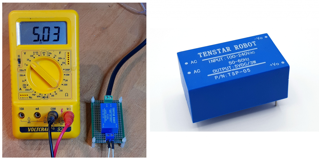
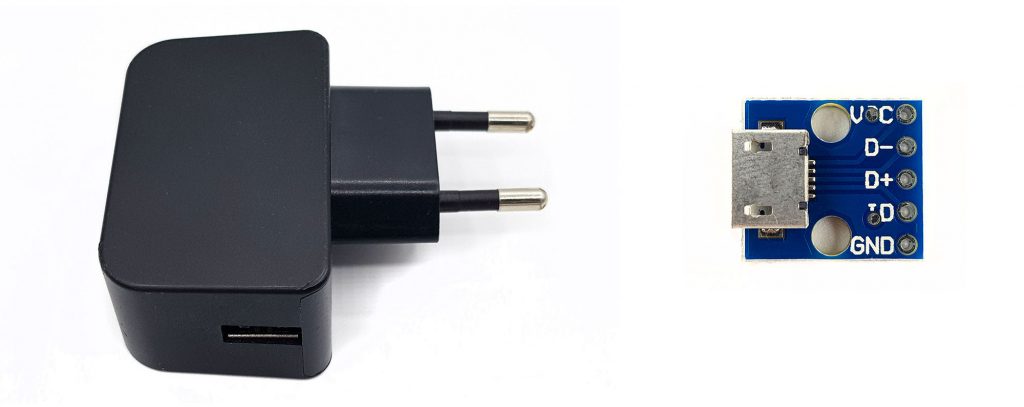
If you want to operate from the power grid and need 5 volts, I would rather recommend such power supplies with USB output. With a small adapter board for < 1 Euro the voltage can then be used comfortably on the breadboard.
Acknowledgement
I found the post picture on Pixabay. I thank the photographer Jonas Manske.