About this post
In this last (yes, really!) article about current sensors I will report on the INA282. In terms of its characteristics, the INA282 can be classified as follows in the series of current sensors discussed so far:
| Sensor | INA282 | INA219 | INA226 | Self-built | ACS712 | MAX471 |
| Measuring principle | external shunt | external shunt | external shunt | external shunt | Hall- effect | internal shunt |
| Signal | analog | digital (I2C) | digital (I2C) | analog | analog | analog |
“External” shunt means that the shunt is not on the IC, but on the modules.
As with previous articles on this topic, I will first discuss the technical characteristics of INA282. Then I show how you operate it with an Arduino (UNO), create a calibration line and finally how you measure the power in addition to the current. I have already shown the latter with other modules, but each post should be understandable on its own if possible.
Technical characteristics
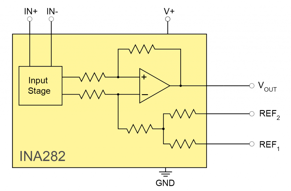
The INA282 determines the current by amplifying the voltage drop across a shunt (low-impedance resistor for measuring currents) and outputting it at pin OUT. To do this, it uses a gain factor of 50 V/V. The INA282 also has a few siblings with higher gain factors:
- INA286: 100 V/V
- INA283: 200 V/V
- INA284: 400 V/V
- INA285: 1000 V/V
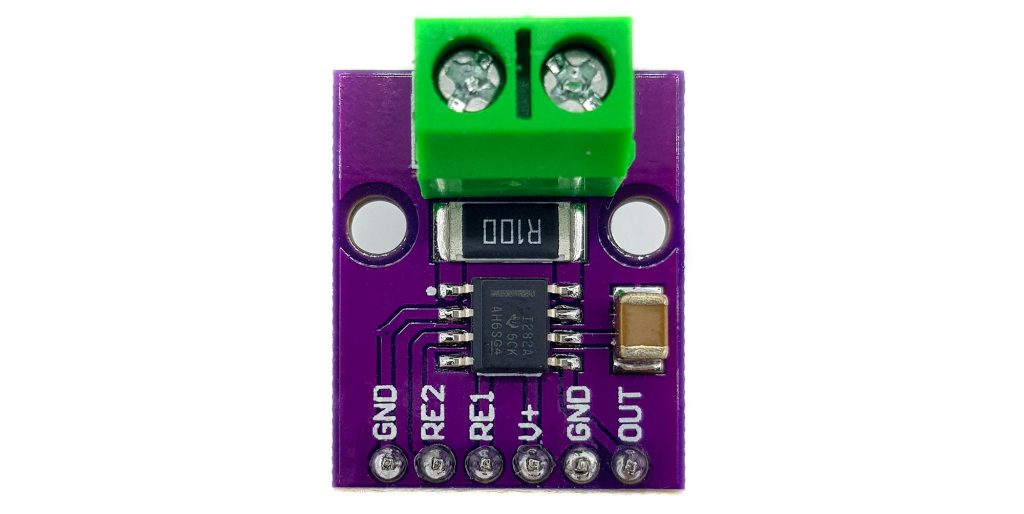
As a module, I found only the INA282 and also only with a shunt of 0.1 Ohm. This means that e.g. 1 ampere causes a voltage drop of 100 millivolts at the shunt. Due to the gain factor of 50, you get a signal voltage of 5 volts in this case. With the bare ICs, on the other hand, you are more flexible and can adjust the range of the signal voltage by choosing the shunt. Or you switch between different shunts and have different measurement ranges in this way.
The INA282 requires a supply voltage of 2.7 to 18 volts and has a maximum current consumption of 900 microamperes. The voltage at its inputs IN+ and IN- can from -14 to +80 volts.
From the internal design, the INA282 is very similar to the op amp variant of the self-built current sensor, which I discussed here.
Further details about the INA282 can be found in the data sheet.
Operating modes
In addition to the current I, the size of the shunt and the amplification factor, the operating voltage VCC and the type of wiring of REF1 and REF2 (RE1/RE2 on the module) determine the voltage level at OUT:
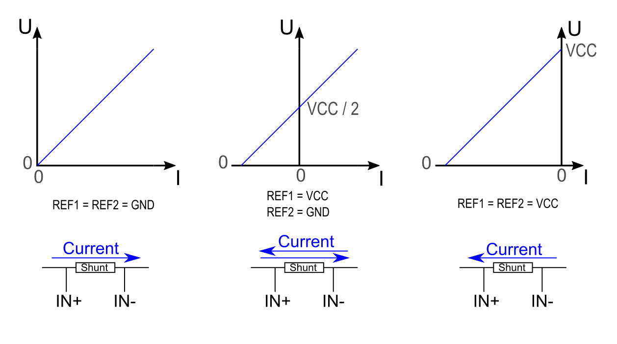
- REF1 and REF2 to GND: at zero ampere, the voltage at OUT is zero. When a current flows from the IN+ connected side of the shunt to the side connected to IN- you measure a positive voltage. With this setup, you can therefore only measure unidirectionally.
- REF1 to VCC, REF2 to GND (or vice versa): at zero ampere you get a voltage of VCC/2. Depending on the current direction, the voltage decreases or increases (bidirectional).
- REF1 and REF2 to VCC: At zero amperes, the voltage at OUT is equal to VCC. With a current flow IN- –> IN+ (via the shunt), the voltage decreases with increasing current. With this setup, you can therefore only measure unidirectionally again.
Further settings are possible by attaching REF1 and REF2 to other reference voltages. More information can be found in the data sheet.
Connection to the Arduino UNO
Since the INA282 only draws a maximum of 900 µA, you can power it via the Arduino. However, you should not have too many other devices attached to the power supply in order not to affect the current measurement. Of course, this is especially true if you select operating modes 2 or 3. Because if the supply voltage fluctuates, your zero point fluctuates.
I’ll only look at operating mode 1. Here’s what your circuit might look like if you use an Arduino UNO:
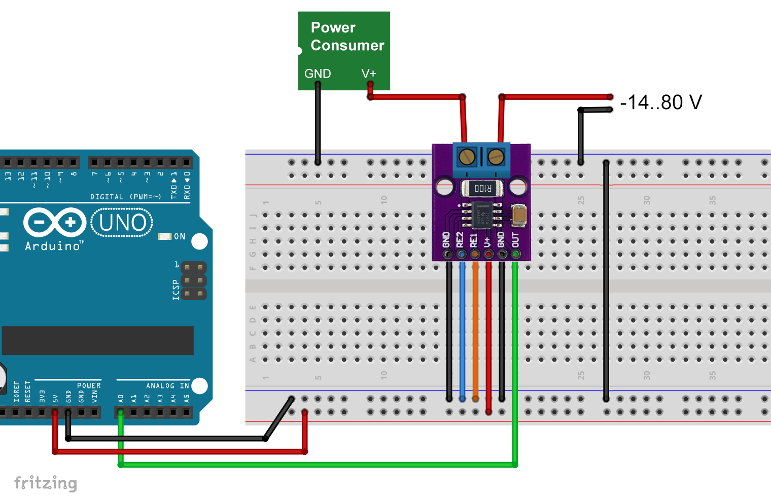
This is the high-side configuration, i.e. the INA282 is placed on the V+ side of the consumer. Alternatively, you can also put it on the GND side, i.e. behind the consumer (low-side configuration).
I could only achieve stable values if I ensured a common mass of consumer circuit and the Arduino.
The consumer current to be determined is usually referred to as bus current. That is why I will continue to use this term.
Creating of a calibration line
For the creation of the calibration line, I measured the bus current with a multimeter, used different consumers and measured the raw values at the analog input A0. However, the Arduino A/D converter tends to fluctuate by +/-2 units. That’s why I averaged 25 individual values each.
void setup() {
  Serial.begin(9600);
}

void loop() {
  unsigned long rawVal = 0;

  for(int i=0; i<25; i++){
    rawVal += analogRead(A0);
    delay(5);
  }

  float meanRawVal = (rawVal / 25.0);
  Serial.println(meanRawVal);
  delay(1000);
}
I then converted the raw values into the voltage U:
![\[ U\;[\text{mV}]=rawV\!al\cdot\frac{5000}{1024} \]](https://wolles-elektronikkiste.de/wp-content/ql-cache/quicklatex.com-4b50f18af04d632cb1ffffb5708dea5d_l3.png "Rendered by QuickLaTeX.com")
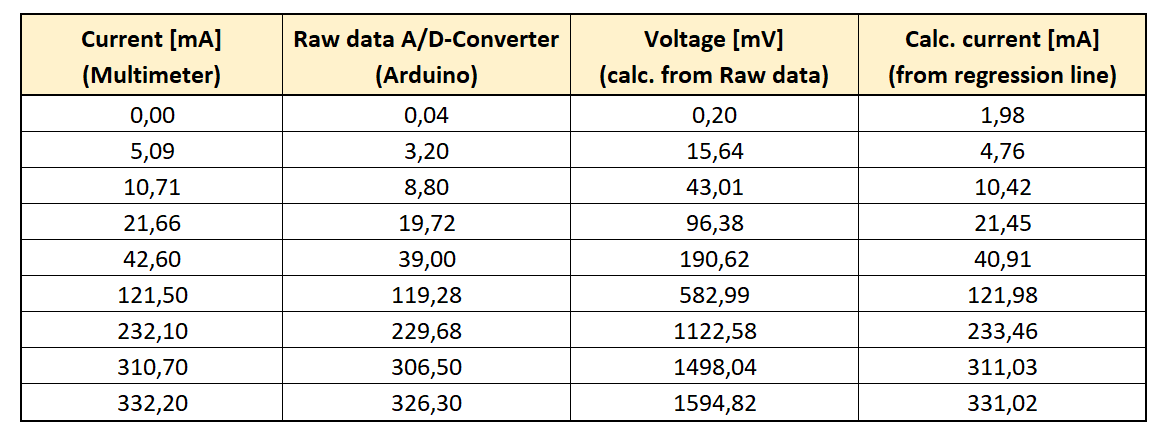
Here’s what the data looked like:
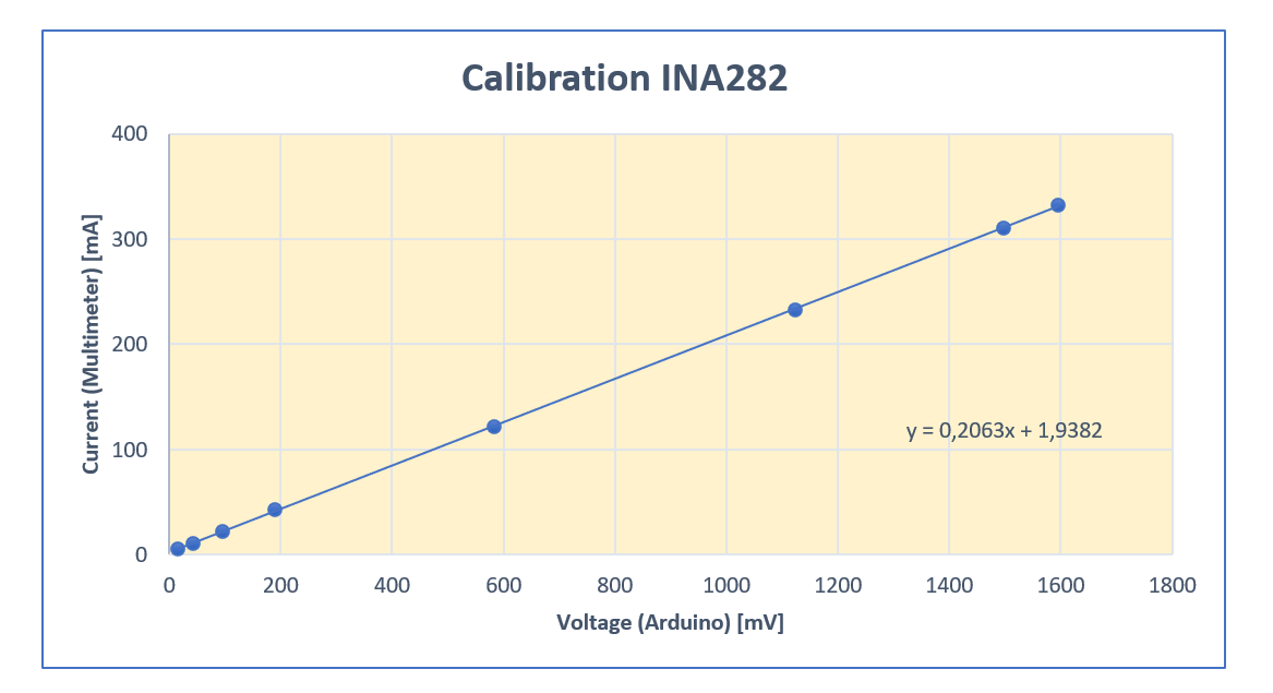
… and the regression (calibration) line created via Excel:
I then inserted the raw values into the formula for the calibration line (see last column of Table 2). The calculated values are fairly consistent with the multimeter values. Only at the zero point the real values deviate a bit from the regression line. That’s why I didn’t include the value at 0 milliamperes.
Further above I had calculated that at 50 times gain and a shunt of 0.1 ohms, a current of 1 ampere should give a signal voltage of 5 volts. The regression line should therefore have a slope of 0.2 mA/mV. Instead, the slope is 0.2063, which is about 3 percent deviation. The measurement fluctuations are below this deviation, at least at currents higher than 10 milliamperes. For accurate measurements, it is therefore worthwhile to do this calibration exercise.
The INA282 as current and power sensor
Once you have applied the calibration procedure, you can now measure unknown currents. In addition, you can also easily add a power measurement feature to your project.
Since you know the bus current, you only need to measure the voltage at V+ of the consumer (bus voltage) and can calculate the power P:
![\[ P = U_{\text{Bus}}\cdot I_{\text{Bus}} \]](https://wolles-elektronikkiste.de/wp-content/ql-cache/quicklatex.com-dfcc2c0792a06b1e24ba163ef31e8e6b_l3.png "Rendered by QuickLaTeX.com")
Here’s what your circuit might look like:
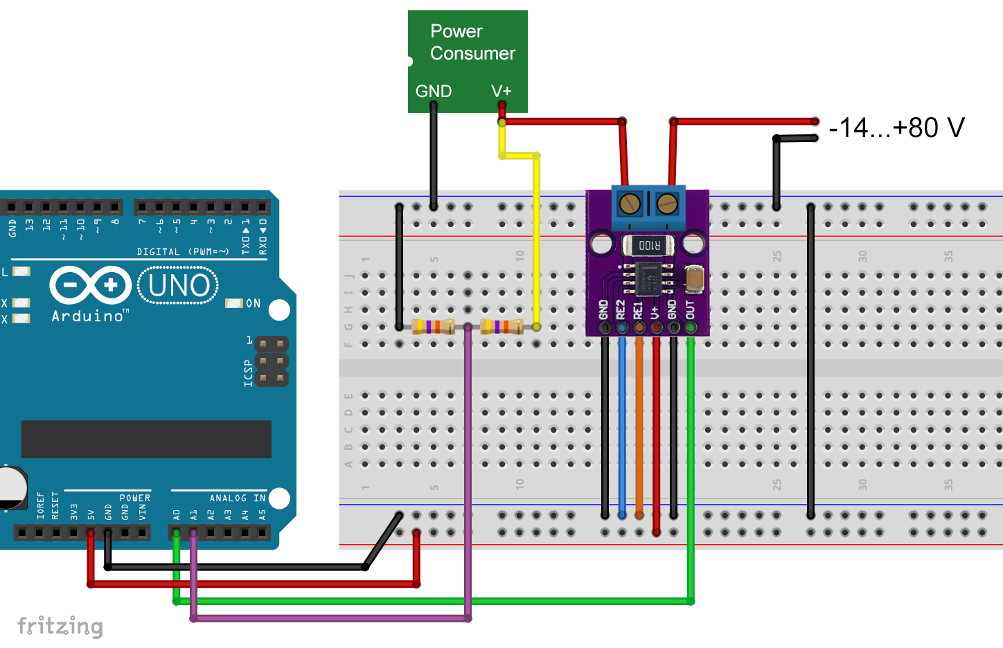
Of course, you have to be careful that there are no more than 5 volts at the analog inputs. Otherwise you can destroy your Arduino. Therefore, use a suitable voltage divider. However, if your power source for the bus only delivers 5 volts, you can, of course, do without it.
Here’s what the full sketch looks like:
const int outPin = A0;
const int busVoltagePin = A1;

void setup() {
  Serial.begin(9600);
  Serial.println("INA282 Current Sensor");
  Serial.println();
}

void loop() {
  float voltage = 0.0;
  unsigned long rawVal = 0;

  for(int i=0; i<25; i++){
    rawVal += analogRead(outPin);
  }

  voltage = (rawVal/25.0) * 5000 / 1024.0;
  Serial.print("V Out         [mV]: ");
  Serial.println(voltage);

  float current_mA = voltage * 0.2063 + 1.9382; // Kalibrierfaktoren
  Serial.print("Busstrom      [mA]: ");
  Serial.println(current_mA);

  voltage = analogRead(busVoltagePin) * 5.0 / 1024.0;
  Serial.print("Busspannung    [V]: ");
  Serial.println(voltage);

  float power_mW = (voltage * current_mA);
  Serial.print("Leistung      [mW]: ");
  Serial.println(power_mW);

  Serial.println("-------------------------------");
  delay(2000);
}
Here’s what it looks like on the serial monitor:
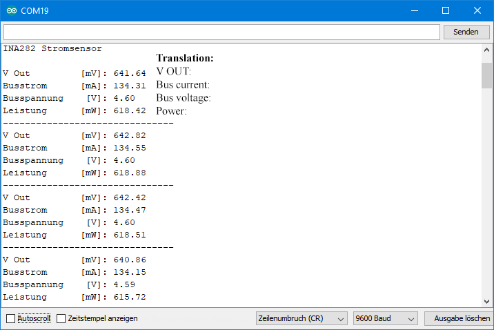
Using the bare INA282 IC
You can also use the bare INA282 (or one of its siblings). There are small adapter boards available (e.g. here) on which you can solder such SMDs. Then you are free in the choice of the shunt.
The pinout of the INA282 looks like this:
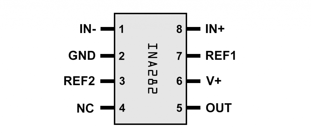
This looks very similar to the outputs of the module. You only have to worry about a shunt between IN+ and IN- and can take everything else from the circuits above.
In my article about the self-built current sensor I have already explained the use of shunts. But I want to point out again that when using “normal” resistors as shunts, the contact resistance on a breadboard can lead to inaccurate values (probably because of the thin connecting wires of the resistor, which are not tight enough in the breadboard). For this reason, the connection to the shunt should be soldered.
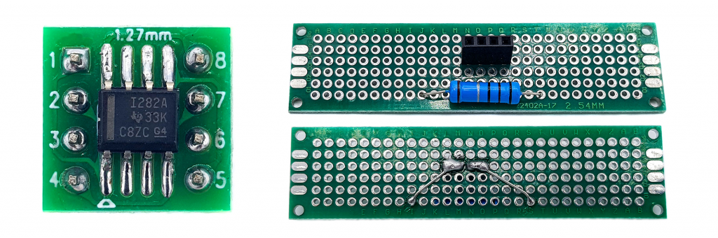
In this way, I was able to determine the same stable values as with the INA282 module.
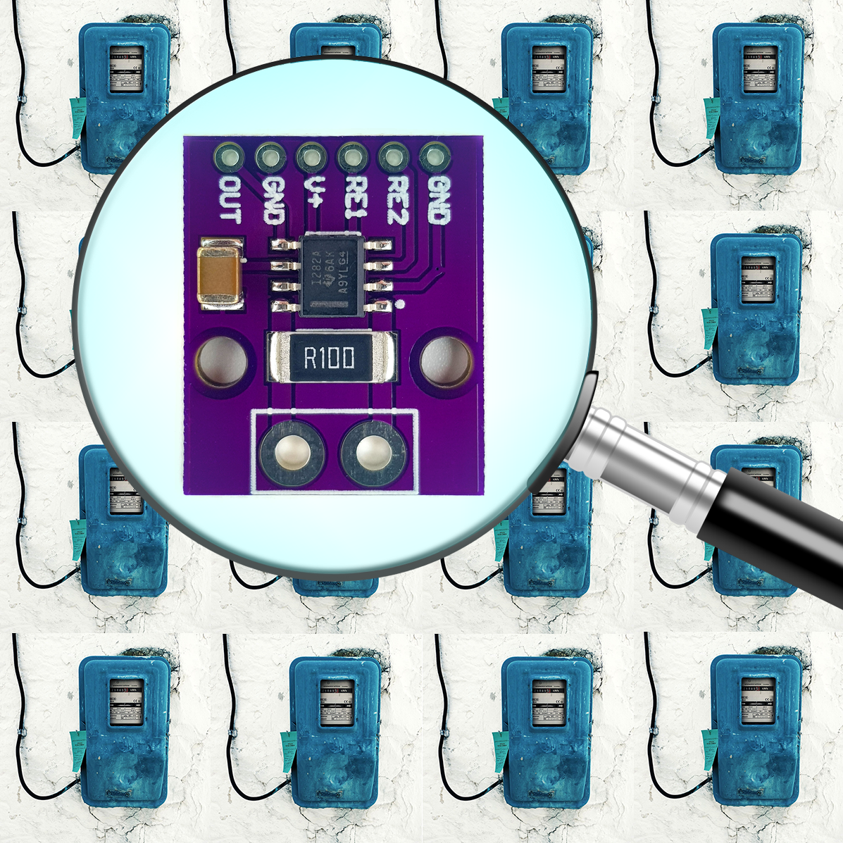
Acknowledgement
As usual, I used Pixabay for parts of my post image. I would therefore like to thank you:
- I took the magnifying glass from OpenClipart-Vectors.
- The already frequently used electricity meter is from the free-photos.
Hi,
Congratulations!
This article help me a lot!
My hobby is build tube amplifiers and this circuit help me to measure quiescent current of exit tubes.
Hugs,
Marcio from Brazil
Hi Marcio, thank you for your kind comment and greetings to Brazil! Have fun and stay healthy!