
About this Post
After reporting on the INA219 in my last post, I would like to introduce the INA226 and my associated library INA226_WE in this article.
In a first approximation, the INA226 is an INA219 with alarm function, which is particularly well suited for monitoring currents. In addition, the INA226 can be used on both the high-side and the low-side. I will come back to other differences to the INA219 in the course of this article.
First of all, I will deal with the measuring principle and the technical data. Then I present the library with its numerous example sketches. Finally, the last part is for those who want to go deeper. It deals with the inner details of the INA226 and the library.
The measuring principle
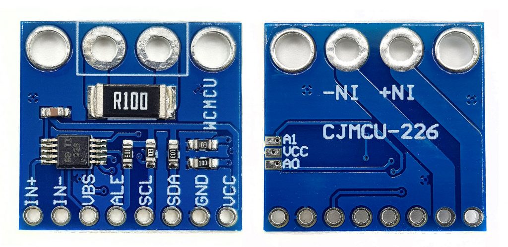
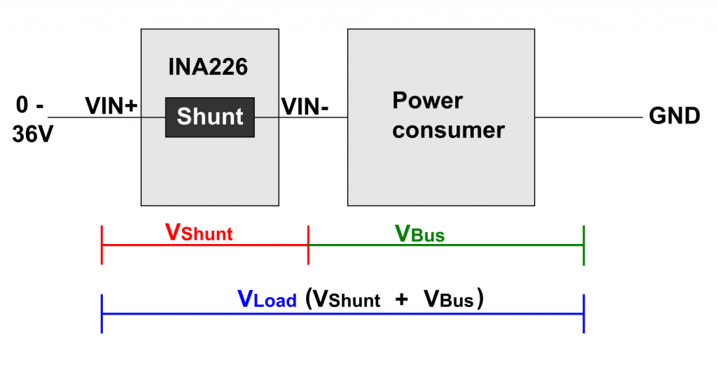
Basically, the INA226 works the same way as the INA219. You conduct the current to be measured via the terminals IN+ and IN- through a shunt (current resistor). An A/D converter measures the voltage drop across the shunt and the INA226 calculates the current from this.
If you use the bare INA226 (the eight-pin IC on the module), then you are free to choose the size of the shunt. The modules have a shunt of 0.1 ohms. In any case, this applies to all models that I have dealt with.
In addition, the INA226 measures the bus voltage, i.e. the voltage drop across consumer. This happens between VBUS and GND. The INA219, on the other hand, measures the bus voltage between IN and GND. That’s why you have to place the INA219 before the consumer (high-side). With the INA226 you are more flexible; you can use it on the high-side as well as on the low-side.
The INA226 calculates the power from the current and the voltage drop across the consumer. It writes the measured values to its data registers, from where you can query them via I²C.
Typical circuit
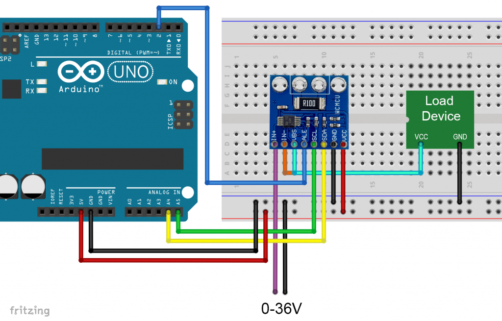
I used the above (high-side) circuit for all example sketches. It is important that the INA226 and the consumer have a common GND, otherwise the measurement of the bus voltage will not work. If you swap IN+ and IN- you will get negative values for the shunt voltage and current.
Some technical data of the INA226 module
- Bus voltage: 0 – 36 volts
- Maximum bus current: 800 milliampere
- Supply voltage: 3 – 5.5 volts
- Power consumption (self-determined):
- Continuous mode: 0.35 mA
- Power-Down Mode: 2.3.µA
- Measurement modes: continuous or on-demand (“triggered”);
- Averaging of 1, 4, 64, 128, 256, 512 or 1024 individual measurements
- A/D conversion time adjustable in eight levels: 0.14 to 8.2 ms
- Data registers:
- Shunt voltage register
- Bus voltage register
- Current register
- Power register
- Communication via I²C, 4 addresses can be set (back of module):
- 0x40: A0, A1 open
- 0x41: A0 closed, A1 open
- 0x44: A0 open, A1 closed
- 0x45: A0, A1 closed
- Programmable alarm pin for limit violations and available data
Further technical data can be found in the manufacturer’s data sheet.
Most INA226 modules have the 0.1 Ω shunt. However, there are also models with 0.01 or 0.02 Ω, for example. With the 0.1 Ω shunt, the maximum current is 0.819175 A. If you use the bare module, you are correspondingly more flexible. I have implemented a function that allows you to use a different resistor.
Use of the INA226 library
You can download the library INA226_WE here from GitHub or install it directly with the Library Manager of the Arduino IDE.
I have written a total of seven example sketches to demonstrate the functions of the library. I will focus most on the example of continuous mode. Many of the functions are used in all sketches and therefore only need to be explained once.
Example 1: Continuous Mode
After you have installed the library and wired your INA226, upload the sketch “Continuous.ino”.
#include <Wire.h>
#include <INA226_WE.h>
#define I2C_ADDRESS 0x40
/* There are several ways to create your INA226 object:
* INA226_WE ina226 = INA226_WE(); -> uses I2C Address = 0x40 / Wire
* INA226_WE ina226 = INA226_WE(I2C_ADDRESS);
* INA226_WE ina226 = INA226_WE(&Wire); -> uses I2C_ADDRESS = 0x40, pass any Wire Object
* INA226_WE ina226 = INA226_WE(&Wire, I2C_ADDRESS);
*/
INA226_WE ina226 = INA226_WE(I2C_ADDRESS);
void setup() {
Serial.begin(115200);
Wire.begin();
if(!ina226.init()){
Serial.println("Failed to init INA226. Check your wiring.");
while(1){}
}
/* Set Number of measurements for shunt and bus voltage which shall be averaged
* Mode * * Number of samples *
INA226_AVERAGE_1 1 (default)
INA226_AVERAGE_4 4
INA226_AVERAGE_16 16
INA226_AVERAGE_64 64
INA226_AVERAGE_128 128
INA226_AVERAGE_256 256
INA226_AVERAGE_512 512
INA226_AVERAGE_1024 1024
*/
//ina226.setAverage(INA226_AVERAGE_16); // choose mode and uncomment for change of default
/* Set conversion time in microseconds
One set of shunt and bus voltage conversion will take:
number of samples to be averaged x conversion time x 2
* Mode * * conversion time *
INA226_CONV_TIME_140 140 µs
INA226_CONV_TIME_204 204 µs
INA226_CONV_TIME_332 332 µs
INA226_CONV_TIME_588 588 µs
INA226_CONV_TIME_1100 1.1 ms (default)
INA226_CONV_TIME_2116 2.116 ms
INA226_CONV_TIME_4156 4.156 ms
INA226_CONV_TIME_8244 8.244 ms
*/
//ina226.setConversionTime(INA226_CONV_TIME_1100); //choose conversion time and uncomment for change of default
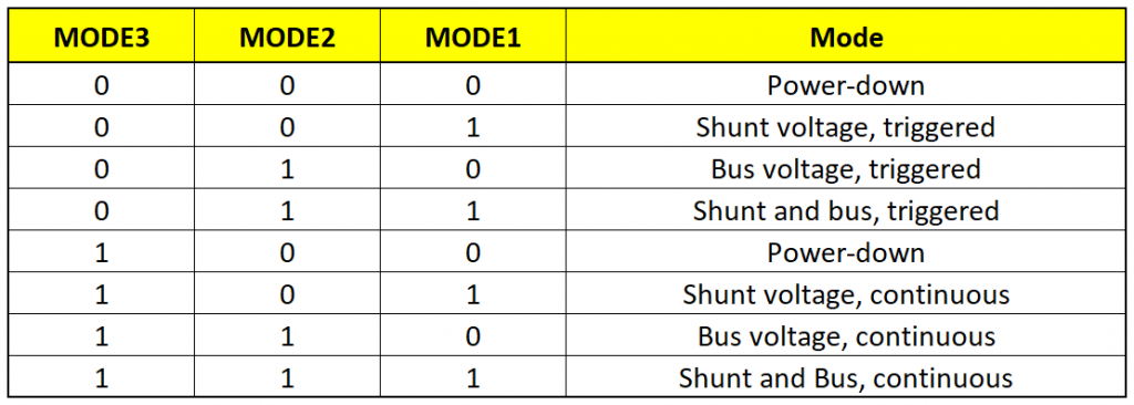
/* Set measure mode
INA226_POWER_DOWN - INA226 switched off
INA226_TRIGGERED - on demand, both current and bus voltage
INA226_TRIGGERED_CURRENT_ONLY - on demand, current only
INA226_TRIGGERERD_BUS_ONLY - on demand, bus voltage only
INA226_CONTINUOUS - continuous, both current and bus voltage (default)
INA226_CONTINUOUS_CURRENT_ONLY - continuous, current only
INA226_CONTINUOUS_BUS_ONLY - continuous, bus voltage only
*/
//ina226.setMeasureMode(INA226_CONTINUOUS); // choose mode and uncomment for change of default
/* If the current values delivered by the INA226 differ by a constant factor
from values obtained with calibrated equipment you can define a correction factor.
Correction factor = current measured with calibrated device / current measured by INA226
Be aware that Imax depends on the real shunt size.
*/
// ina226.setCorrectionFactor(0.95);
Serial.println("INA226 Current Sensor Example Sketch - Continuous");
ina226.waitUntilConversionCompleted(); //if you comment this line the first data might be zero
}
void loop() {
float shuntVoltage_mV = 0.0;
float loadVoltage_V = 0.0;
float busVoltage_V = 0.0;
float current_mA = 0.0;
float power_mW = 0.0;
shuntVoltage_mV = ina226.getShuntVoltage_mV();
busVoltage_V = ina226.getBusVoltage_V();
current_mA = ina226.getCurrent_mA();
power_mW = ina226.getBusPower();
loadVoltage_V = busVoltage_V + (shuntVoltage_mV/1000);
checkForI2cErrors();
Serial.print("Shunt Voltage [mV]: "); Serial.println(shuntVoltage_mV);
Serial.print("Bus Voltage [V]: "); Serial.println(busVoltage_V);
Serial.print("Load Voltage [V]: "); Serial.println(loadVoltage_V);
Serial.print("Current[mA]: "); Serial.println(current_mA);
Serial.print("Bus Power [mW]: "); Serial.println(power_mW);
if(!ina226.overflow){
Serial.println("Values OK - no overflow");
}
else{
Serial.println("Overflow! Choose higher current range");
}
Serial.println();
delay(3000);
}
void checkForI2cErrors(){
byte errorCode = ina226.getI2cErrorCode();
if(errorCode){
Serial.print("I2C error: ");
Serial.println(errorCode);
switch(errorCode){
case 1:
Serial.println("Data too long to fit in transmit buffer");
break;
case 2:
Serial.println("Received NACK on transmit of address");
break;
case 3:
Serial.println("Received NACK on transmit of data");
break;
case 4:
Serial.println("Other error");
break;
case 5:
Serial.println("Timeout");
break;
default:
Serial.println("Can't identify the error");
}
if(errorCode){
while(1){}
}
}
}
Parameter setting using the example of continuous mode
INA226_WE ina226 = INA226_WE() creates your IN226 object. You can pass the I2C address and / or a wire object. The latter allows you to use both I2C buses of an ESP32, for example.
The init() function activates the INA226 with the default values. To change these basic settings, you can vary three parameters in the setup:
- Set the number of individual measurements for the shunt and bus voltage conversion with
setAverage()- 1, 4, 16, 64, 128, 256, 512 or 1024 individual measurements are averaged
- Setting the A/D conversion time for the shunt and bus voltage with
setConvTime()- 8 levels adjustable between 140 µs and 8.244 ms
- Note: obtaining a data set of shunt and bus voltage takes twice the time
- Setting the measurement mode with
setMeasureMode()- INA226_CONTINUOUS – continuous measurement (current and bus voltage, current only or bus voltage only)
- INA226_TRIGGERED – “on request” (current and bus voltage, current only, or bus voltage only)
- INA226_POWER_DOWN – switches off the INA226. But better use the more comfortable
powerDown()function, which is explained below. - The INA226 actually allows determining shunt or bus voltages – but I did not implement that. Using my library, the measurements are only available in a double pack.
With setCorrectionFactor() you can introduce a correction factor if the current values determined with the INA226 should differ from those determined by you, for example, with calibrated measuring instruments. The factor is the quotient of the exact and the INA226 value.
Other functions used in the example
You can query the data registers of the INA226 at any time. They contain the last measured value. Before the first measurement is completed, all values are zero. With waitUntilConversionCompleted() you can wait until the current measurement has been completed.
Using readAndClearFlags() the overflow and alarm flags are read. In this example sketch, we need this call only to update the state of the variable overflow, which – if true – signals the overflow of a register.
The functions for reading the data registers, such as getShuntVoltage_mV(), should be self-explanatory.
Calculation of the measurement time
The duration of a measurement results from the number of individual measurements (averages) and the conversion time. If current and bus voltage are measured, twice the time is required:
![\[ duration = Number_{averages} \cdot ConversionTime\cdot 2 \]](https://wolles-elektronikkiste.de/wp-content/ql-cache/quicklatex.com-e0e0b8f35644747fe967f014fb8f831c_l3.png "Rendered by QuickLaTeX.com")
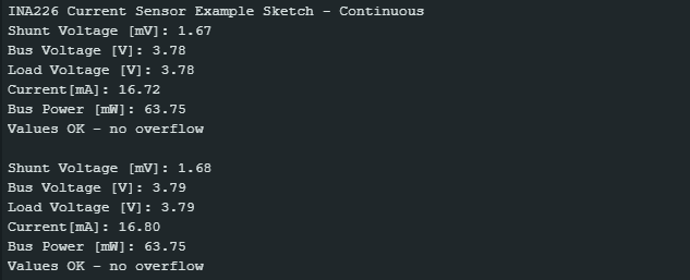
Output
And this is what the output of the sketch looks like on the serial monitor:
Example 2: On-Demand (Triggered) Mode
You set the triggered mode with setMeasureMode(TRIGGERED). Each measurement is started manually with startSingleMeasurement(). I have programmed the function to automatically wait until the current readings are available. So you don’t need to call waitUntilConversionCompleted() in triggered mode. However, this function blocks the sketch for the measurement duration. If you don’t want this, then use the startSingleMeasurementNoWait() function. You can find a sketch for this (Triggered_non_blocking.ino) in the library example sketches.
Otherwise, the sketch is identical to Continuous.ino.
#include <Wire.h>
#include <INA226_WE.h>
#define I2C_ADDRESS 0x40

/* There are several ways to create your INA226 object:
 * INA226_WE ina226 = INA226_WE(); -> uses I2C Address = 0x40 / Wire
 * INA226_WE ina226 = INA226_WE(I2C_ADDRESS);
 * INA226_WE ina226 = INA226_WE(&Wire); -> uses I2C_ADDRESS = 0x40, pass any Wire Object
 * INA226_WE ina226 = INA226_WE(&Wire, I2C_ADDRESS);
 */
INA226_WE ina226 = INA226_WE(I2C_ADDRESS);

void setup() {
  Serial.begin(115200);
  Wire.begin();
  if(!ina226.init()){
    Serial.println("Failed to init INA226. Check your wiring.");
    while(1){}
  }

  /* Set Number of measurements for shunt and bus voltage which shall be averaged
       * Mode *         * Number of samples *
    INA226_AVERAGE_1            1 (default)
    INA226_AVERAGE_4            4
    INA226_AVERAGE_16           8
    INA226_AVERAGE_64          64
    INA226_AVERAGE_128        128
    INA226_AVERAGE_256        256
    INA226_AVERAGE_512        512
    INA226_AVERAGE_1024      1024
  */
  //ina226.setAverage(INA226_AVERAGE_1); // choose mode and uncomment for change of default

  /* Set conversion time in microseconds
    One set of shunt and bus voltage conversion will take:
    number of samples to be averaged x conversion time x 2

       * Mode *              * conversion time *
    INA226_CONV_TIME_140          140 µs
    INA226_CONV_TIME_204          204 µs
    INA226_CONV_TIME_332          332 µs
    INA226_CONV_TIME_588          588 µs
    INA226_CONV_TIME_1100         1.1 ms (default)
    INA226_CONV_TIME_2116       2.116 ms
    INA226_CONV_TIME_4156       4.156 ms
    INA226_CONV_TIME_8244       8.244 ms
  */
  //ina226.setConversionTime(INA226_CONV_TIME_1100); //choose conversion time and uncomment for change of default

  /* Set measure mode
    INA226_POWER_DOWN              - INA226 switched off
    INA226_TRIGGERED               - on demand, both current and bus voltage
    INA226_TRIGGERED_CURRENT_ONLY  - on demand, current only
    INA226_TRIGGERERD_BUS_ONLY     - on demand, bus voltage only
    INA226_CONTINUOUS              - continuous, both current and bus voltage (default)
    INA226_CONTINUOUS_CURRENT_ONLY - continuous, current only
    INA226_CONTINUOUS_BUS_ONLY     - continuous, bus voltage only
  */
  ina226.setMeasureMode(INA226_TRIGGERED); // choose mode and uncomment for change of default

  /* If the current values delivered by the INA226 differ by a constant factor
    from values obtained with calibrated equipment you can define a correction factor.
    Correction factor = current measured with calibrated device / current measured by INA226
    Be aware that Imax depends on the real shunt size.
  */
  // ina226.setCorrectionFactor(0.95);

  Serial.println("INA226 Current Sensor Example Sketch - Triggered");

  // ina226.waitUntilConversionCompleted(); //makes no sense - in triggered mode we wait anyway for comleted conversion
}

void loop() {
  float shuntVoltage_mV = 0.0;
  float loadVoltage_V = 0.0;
  float busVoltage_V = 0.0;
  float current_mA = 0.0;
  float power_mW = 0.0;

  ina226.startSingleMeasurement();
  ina226.readAndClearFlags();
  shuntVoltage_mV = ina226.getShuntVoltage_mV();
  busVoltage_V = ina226.getBusVoltage_V();
  current_mA = ina226.getCurrent_mA();
  power_mW = ina226.getBusPower();
  loadVoltage_V  = busVoltage_V + (shuntVoltage_mV/1000);
  checkForI2cErrors();

  Serial.print("Shunt Voltage [mV]: "); Serial.println(shuntVoltage_mV);
  Serial.print("Bus Voltage [V]: "); Serial.println(busVoltage_V);
  Serial.print("Load Voltage [V]: "); Serial.println(loadVoltage_V);
  Serial.print("Current[mA]: "); Serial.println(current_mA);
  Serial.print("Bus Power [mW]: "); Serial.println(power_mW);
  if(!ina226.overflow){
    Serial.println("Values OK - no overflow");
  }
  else{
    Serial.println("Overflow! Choose higher current range");
  }
  Serial.println();

  delay(3000);
}

void checkForI2cErrors(){
  byte errorCode = ina226.getI2cErrorCode();
  if(errorCode){
    Serial.print("I2C error: ");
    Serial.println(errorCode);
    switch(errorCode){
      case 1:
        Serial.println("Data too long to fit in transmit buffer");
        break;
      case 2:
        Serial.println("Received NACK on transmit of address");
        break;
      case 3:
        Serial.println("Received NACK on transmit of data");
        break;
      case 4:
        Serial.println("Other error");
        break;
      case 5:
        Serial.println("Timeout");
        break;
      default:
        Serial.println("Can't identify the error");
    }
    if(errorCode){
      while(1){}
    }
  }
}
Example 3: Power-Down Mode
In power-down mode, you bring down the power consumption of the INA226 from approx. 0.35 mA to approx. 2.3 µA (own measurements).
The example sketch PowerDown.ino shows the power-down mode in action. The sketch initializes the INA226 with the default parameters. Five sets of measurements are output every three seconds. The function powerDown() then saves the contents of the configuration register and disables the INA226. The function powerUp() writes back the copy of the configuration register. On the one hand, this writing process awakens the INA226, on the other hand it ensures that the INA226 returns to the previously selected mode (here: continuous).
#include <Wire.h>
#include <INA226_WE.h>
#define I2C_ADDRESS 0x40

/* There are several ways to create your INA226 object:
 * INA226_WE ina226 = INA226_WE(); -> uses I2C Address = 0x40 / Wire
 * INA226_WE ina226 = INA226_WE(I2C_ADDRESS);
 * INA226_WE ina226 = INA226_WE(&Wire); -> uses I2C_ADDRESS = 0x40, pass any Wire Object
 * INA226_WE ina226 = INA226_WE(&Wire, I2C_ADDRESS);
 */
INA226_WE ina226 = INA226_WE(I2C_ADDRESS);

void setup() {
  Serial.begin(115200);
  Wire.begin();
  // default parameters are set - for change check the other examples
  ina226.init();
  Serial.println("INA226 Current Sensor Example Sketch - PowerDown");
  Serial.println("Continuous Sampling starts");
  Serial.println();
}

void loop() {
  for(int i=0; i<5; i++){
    continuousSampling();
    delay(3000);
  }

  Serial.println("Power down for 10s");
  ina226.powerDown();
  for(int i=0; i<10; i++){
    Serial.print(".");
    delay(1000);
  }

  Serial.println("Power up!");
  Serial.println("");
  ina226.powerUp();
}

void continuousSampling(){
  float shuntVoltage_mV = 0.0;
  float loadVoltage_V = 0.0;
  float busVoltage_V = 0.0;
  float current_mA = 0.0;
  float power_mW = 0.0;

  ina226.readAndClearFlags();
  shuntVoltage_mV = ina226.getShuntVoltage_mV();
  busVoltage_V = ina226.getBusVoltage_V();
  current_mA = ina226.getCurrent_mA();
  power_mW = ina226.getBusPower();
  loadVoltage_V  = busVoltage_V + (shuntVoltage_mV/1000);

  Serial.print("Shunt Voltage [mV]: "); Serial.println(shuntVoltage_mV);
  Serial.print("Bus Voltage [V]: "); Serial.println(busVoltage_V);
  Serial.print("Load Voltage [V]: "); Serial.println(loadVoltage_V);
  Serial.print("Current[mA]: "); Serial.println(current_mA);
  Serial.print("Bus Power [mW]: "); Serial.println(power_mW);
  if(!ina226.overflow){
    Serial.println("Values OK - no overflow");
  }
  else{
    Serial.println("Overflow! Choose higher current range");
  }
  Serial.println();
}
Example 4: Conversion Ready Alarm
Now upload “Continuous_Alert_Controlled.ino”. With this example, you get to know the alert pin. First, a high number of individual measurements to be averaged is set at 512. We select 8.244 milliseconds as the conversion time. This means that the combination of shunt and bus voltage measurement takes around 8.4 seconds. We select CONTINUOUS as the measurement mode. The function enableConvReadyAlert() activates the alert pin, which is active-low by default. The alert pin is connected to the Arduino Pin 2, for which we set up an interrupt.
When a measurement is finished, the alert pin goes to LOW and an interrupt is triggered. The variable “event” becomes true and the if block is processed in the main loop. First, readAndClearFlags() is executed. This will delete the conversion ready flag and also read the overflow flag. The measurement data is read and displayed. The interrupt on pin 2 was deactivated after triggering and is switched on again after the values have been output.
#include <Wire.h>
#include <INA226_WE.h>
#define I2C_ADDRESS 0x40

int interruptPin = 2;
volatile bool event = false;

/* There are several ways to create your INA226 object:
 * INA226_WE ina226 = INA226_WE(); -> uses I2C Address = 0x40 / Wire
 * INA226_WE ina226 = INA226_WE(I2C_ADDRESS);
 * INA226_WE ina226 = INA226_WE(&Wire); -> uses I2C_ADDRESS = 0x40, pass any Wire Object
 * INA226_WE ina226 = INA226_WE(&Wire, I2C_ADDRESS);
 */
INA226_WE ina226 = INA226_WE(I2C_ADDRESS);

void setup() {
  Serial.begin(115200);
  pinMode(interruptPin, INPUT_PULLUP); // for modules without internal pullup
  Wire.begin();
  ina226.init();

  /* Set Number of measurements for shunt and bus voltage which shall be averaged
    * Mode *     * Number of samples *
    INA226_AVERAGE_1            1 (default)
    INA226_AVERAGE_4            4
    INA226_AVERAGE_16          16
    INA226_AVERAGE_64          64
    INA226_AVERAGE_128        128
    INA226_AVERAGE_256        256
    INA226_AVERAGE_512        512
    INA226_AVERAGE_1024      1024
  */
  ina226.setAverage(INA226_AVERAGE_1024);

  /* Set conversion time in microseconds
     One set of shunt and bus voltage conversion will take:
     number of samples to be averaged x conversion time x 2

    * Mode *                * conversion time *
    INA226_CONV_TIME_140          140 µs
    INA226_CONV_TIME_204          204 µs
    INA226_CONV_TIME_332          332 µs
    INA226_CONV_TIME_588          588 µs
    INA226_CONV_TIME_1100         1.1 ms (default)
    INA226_CONV_TIME_2116       2.116 ms
    INA226_CONV_TIME_4156       4.156 ms
    INA226_CONV_TIME_8244       8.244 ms
  */
  ina226.setConversionTime(INA226_CONV_TIME_8244); // Conversion ready after conversion time x number of averages x 2

  /* Set measure mode
    INA226_POWER_DOWN              - INA226 switched off
    INA226_TRIGGERED               - on demand, both current and bus voltage
    INA226_TRIGGERED_CURRENT_ONLY  - on demand, current only
    INA226_TRIGGERERD_BUS_ONLY     - on demand, bus voltage only
    INA226_CONTINUOUS              - continuous, both current and bus voltage (default)
    INA226_CONTINUOUS_CURRENT_ONLY - continuous, current only
    INA226_CONTINUOUS_BUS_ONLY     - continuous, bus voltage only
  */
  //ina226.setMeasureMode(INA226_CONTINUOUS); // choose mode and uncomment for change of default

  /* If the current values delivered by the INA226 differ by a constant factor
    from values obtained with calibrated equipment you can define a correction factor.
    Correction factor = current measured with calibrated device / current measured by INA226
    Be aware that Imax depends on the real shunt size.
  */
  // ina226.setCorrectionFactor(0.95);

  Serial.println("INA226 Current Sensor Example Sketch - Continuous_Alert_Controlled");

  attachInterrupt(digitalPinToInterrupt(interruptPin), alert, FALLING);

  ina226.enableConvReadyAlert(); // an interrupt will occur on interrupt pin when conversion is ready
}

void loop() {
  if(event){
    ina226.readAndClearFlags(); // reads interrupt and overflow flags and deletes them
    displayResults();
    attachInterrupt(digitalPinToInterrupt(interruptPin), alert, FALLING);
    event = false;
  }

  delay(100);
}

void displayResults(){
  float shuntVoltage_mV = 0.0;
  float loadVoltage_V = 0.0;
  float busVoltage_V = 0.0;
  float current_mA = 0.0;
  float power_mW = 0.0;

  shuntVoltage_mV = ina226.getShuntVoltage_mV();
  busVoltage_V = ina226.getBusVoltage_V();
  current_mA = ina226.getCurrent_mA();
  power_mW = ina226.getBusPower();
  loadVoltage_V  = busVoltage_V + (shuntVoltage_mV/1000);

  Serial.print("Shunt Voltage [mV]: "); Serial.println(shuntVoltage_mV);
  Serial.print("Bus Voltage [V]: "); Serial.println(busVoltage_V);
  Serial.print("Load Voltage [V]: "); Serial.println(loadVoltage_V);
  Serial.print("Current[mA]: "); Serial.println(current_mA);
  Serial.print("Bus Power [mW]: "); Serial.println(power_mW);
  if(!ina226.overflow){
    Serial.println("Values OK - no overflow");
  }
  else{
    Serial.println("Overflow! Choose higher current range");
  }
  Serial.println();
}

void alert(){
  event = true;
  detachInterrupt(digitalPinToInterrupt(interruptPin));
}
Practical application of the Conversion Ready Alert
During the long 8 seconds between measurements, the Arduino or the microcontroller you are using in your project has nothing to do. This consumes valuable electricity in battery-powered projects. So just send your microcontroller to sleep and let it wake up through the interrupt. If you don’t know how to do it, look here at my post on this subject.
Example 5: Limit Alert
I would like to introduce you to the Limit Alarm using the sketch Limit_Alert.ino. The INA226 runs in triggered mode. On the Arduino side, an interrupt on pin 2 is set up again.
The function enableAlertLatch() sets the alarm pin so that it is active when an alarm is raised until it is manually readAndClearFlags() set inactive again. Without this setup, the pin would be automatically reset if the next measured value is within the limits.
With setAlertType() you determine the limit and which of the measured values is observed. You can specify a min or max limit for the shunt voltage, bus voltage, or current. For the power you can only set a max limit. Actually, the INA226 has no alarm function for the current, I implemented this via a detour.
And that’s it. When the set limit is exceeded, the alarm pin becomes active, the interrupt is triggered and the measured values are read. However, the alarm is triggered for each individual measurement and not only after measurements set via averages have been completed.
You have to be a bit careful with the readAndClearFlags() function. When you read the flags to evaluate them, you delete them. If the alarm condition still exists, the alarm pin becomes active again immediately. If this happens before the interrupt is reactivated, everything gets confused. The alarm pin would already be low, while the interrupt pin would wait for a falling event. It could wait for a very long time! This is why readAndClearFlags() is called again after the interrupt has been reactivated. Separating the reading and deletion of the flags would be a little easier to control, but this is not implemented in INA226.
#include <Wire.h>
#include <INA226_WE.h>
#define I2C_ADDRESS 0x40
#define SAMPLING_PERIOD 500
#define OUTPUT_PERIOD 2000

int interruptPin = 2;
volatile bool limitEvent = false;

/* There are several ways to create your INA226 object:
 * INA226_WE ina226 = INA226_WE(); -> uses I2C Address = 0x40 / Wire
 * INA226_WE ina226 = INA226_WE(I2C_ADDRESS);
 * INA226_WE ina226 = INA226_WE(&Wire); -> uses I2C_ADDRESS = 0x40, pass any Wire Object
 * INA226_WE ina226 = INA226_WE(&Wire, I2C_ADDRESS);
 */
INA226_WE ina226 = INA226_WE(I2C_ADDRESS);

void setup() {
  Serial.begin(115200);
  pinMode(interruptPin, INPUT_PULLUP); // for modules without internal pullup
  Wire.begin();
  ina226.init();

  /* Set Number of measurements for shunt and bus voltage which shall be averaged
      * Mode *          * Number of samples *
    INA226_AVERAGE_1            1 (default)
    INA226_AVERAGE_4            4
    INA226_AVERAGE_16          16
    INA226_AVERAGE_64          64
    INA226_AVERAGE_128        128
    INA226_AVERAGE_256        256
    INA226_AVERAGE_512        512
    INA226_AVERAGE_1024      1024
  */
  // ina226.setAverage(INA226_AVERAGE_1024);

  /* Set conversion time in microseconds
     One set of shunt and bus voltage conversion will take:
     number of samples to be averaged x conversion time x 2

       * Mode *              * conversion time *
    INA226_CONV_TIME_140          140 µs
    INA226_CONV_TIME_204          204 µs
    INA226_CONV_TIME_332          332 µs
    INA226_CONV_TIME_588          588 µs
    INA226_CONV_TIME_1100         1.1 ms (default)
    INA226_CONV_TIME_2116       2.116 ms
    INA226_CONV_TIME_4156       4.156 ms
    INA226_CONV_TIME_8244       8.244 ms
  */
  // ina226.setConversionTime(INA226_CONV_TIME_8244);

  /* Set measure mode
    INA226_POWER_DOWN              - INA226 switched off
    INA226_TRIGGERED               - on demand, both current and bus voltage
    INA226_TRIGGERED_CURRENT_ONLY  - on demand, current only
    INA226_TRIGGERERD_BUS_ONLY     - on demand, bus voltage only
    INA226_CONTINUOUS              - continuous, both current and bus voltage (default)
    INA226_CONTINUOUS_CURRENT_ONLY - continuous, current only
    INA226_CONTINUOUS_BUS_ONLY     - continuous, bus voltage only
  */
  ina226.setMeasureMode(INA226_TRIGGERED); // choose mode and uncomment for change of default

  /* If the current values delivered by the INA226 differ by a constant factor
    from values obtained with calibrated equipment you can define a correction factor.
    Correction factor = current measured with calibrated device / current measured by INA226
    Be aware that Imax depends on the real shunt size.
  */
  // ina226.setCorrectionFactor(0.95);

  Serial.println("INA226 Current Sensor Example Sketch - Limit_Alert");

  /* In the default mode the limit interrupt flag will be deleted after the next measurement within limits.
    With enableAltertLatch(), the flag will have to be deleted with readAndClearFlags().
  */
    ina226.enableAlertLatch();

  /* Set the alert type and the limit
      * Mode *        * Description *           * limit unit *
    INA226_SHUNT_OVER     Shunt Voltage over limit          mV
    INA226_SHUNT_UNDER    Shunt Voltage under limit         mV
    INA226_CURRENT_OVER   Current over limit                mA
    INA226_CURRENT_UNDER  Current under limit               mA
    INA226_BUS_OVER       Bus Voltage over limit            V
    INA226_BUS_UNDER      Bus Voltage under limit           V
    INA226_POWER_OVER     Power over limit                  mW
  */
  ina226.setAlertType(INA226_POWER_OVER, 250.0); // alert, if power > 250.0 mW

  attachInterrupt(digitalPinToInterrupt(interruptPin), alert, FALLING);
}

void loop() {
  static unsigned long lastMeasurement = 0;
  static unsigned long lastOutput = 0;

  if(millis() - lastMeasurement >= SAMPLING_PERIOD) {
    ina226.startSingleMeasurementNoWait();
    lastMeasurement = millis();
  }

  if(millis() - lastOutput >= OUTPUT_PERIOD) {
    lastOutput = millis();
    displayResults();
  }

  if(limitEvent){
    ina226.readAndClearFlags(); // reads interrupt and overflow flags and deletes them
    Serial.println("ALERT!");
    displayResults();
    lastOutput = millis();
    limitEvent = false;
    attachInterrupt(digitalPinToInterrupt(interruptPin), alert, FALLING);
    ina226.readAndClearFlags();
  }
}

void displayResults(){
  float shuntVoltage_mV = 0.0;
  float loadVoltage_V = 0.0;
  float busVoltage_V = 0.0;
  float current_mA = 0.0;
  float power_mW = 0.0;

  shuntVoltage_mV = ina226.getShuntVoltage_mV();
  busVoltage_V = ina226.getBusVoltage_V();
  current_mA = ina226.getCurrent_mA();
  power_mW = ina226.getBusPower();
  loadVoltage_V  = busVoltage_V + (shuntVoltage_mV/1000);

  Serial.print("Shunt Voltage [mV]: "); Serial.println(shuntVoltage_mV);
  Serial.print("Bus Voltage [V]: "); Serial.println(busVoltage_V);
  Serial.print("Load Voltage [V]: "); Serial.println(loadVoltage_V);
  Serial.print("Current[mA]: "); Serial.println(current_mA);
  Serial.print("Bus Power [mW]: "); Serial.println(power_mW);
  if(!ina226.overflow){
    Serial.println("Values OK - no overflow");
  }
  else{
    Serial.println("Overflow! Choose higher current range");
  }
  Serial.println();
}

void alert(){
  limitEvent = true;
  detachInterrupt(digitalPinToInterrupt(interruptPin));
}
Example 6: Limit and Conversion Alert
I hope you are still motivated – that is the last example. With the sketch Limit_And_Conversion_Alert.ino I want to show how you can use the limit and the conversion ready alarm side by side. Both alarms are activated as in the previous sketches.
In the event of an alarm, you now want to be able to distinguish which condition triggered the alarm. In case of alarm, read the flags via readAndClearFlags() . This will update the variables limitAlert and convAltert and allow you to query them.
#include <Wire.h>
#include <INA226_WE.h>
#define I2C_ADDRESS 0x40

int interruptPin = 2;
volatile bool event = false;

/* There are several ways to create your INA226 object:
 * INA226_WE ina226 = INA226_WE(); -> uses I2C Address = 0x40 / Wire
 * INA226_WE ina226 = INA226_WE(I2C_ADDRESS);
 * INA226_WE ina226 = INA226_WE(&Wire); -> uses I2C_ADDRESS = 0x40, pass any Wire Object
 * INA226_WE ina226 = INA226_WE(&Wire, I2C_ADDRESS);
 */
INA226_WE ina226 = INA226_WE(I2C_ADDRESS);

void setup() {
  Serial.begin(115200);
  pinMode(interruptPin, INPUT_PULLUP); // for modules without internal pullup
  Wire.begin();
  ina226.init();

  // Conversion will be ready after conversion time x number of averages x 2
  ina226.setAverage(INA226_AVERAGE_512);
  ina226.setConversionTime(INA226_CONV_TIME_8244);
  // ina226.setCorrectionFactor(0.95);

  Serial.println("INA226 Current Sensor Example Sketch - Limit_And_Conversion_Alert");

  /* In the default mode the limit interrupt flag will be deleted after the next measurement within limits.
    With enableAltertLatch(), the flag will have to be deleted with readAndClearFlags().
  */
  ina226.enableAlertLatch();

  /* Set the alert type and the limit
      * Mode *              * Description *           * limit unit *
    INA226_SHUNT_OVER     Shunt Voltage over limit          mV
    INA226_SHUNT_UNDER    Shunt Voltage under limit         mV
    INA226_CURRENT_OVER   Current over limit                mA
    INA226_CURRENT_UNDER  Current under limit               mA
    INA226_BUS_OVER       Bus Voltage over limit            V
    INA226_BUS_UNDER      Bus Voltage under limit           V
    INA226_POWER_OVER     Power over limit                  mW
  */
  ina226.setAlertType(INA226_CURRENT_UNDER, 3.0); // alert, if current is below 3.0 mA
  ina226.enableConvReadyAlert(); // In this example we also enable the conversion ready alert interrupt

  attachInterrupt(digitalPinToInterrupt(interruptPin), alert, FALLING);
}

void loop() {
  static unsigned long lastLimitAlert = 0;
  if(event){
    ina226.readAndClearFlags();
    if(ina226.convAlert){
      Serial.println("Conversion Alert!!!!");
      displayResults();
    }

  /*
    The limit alert is fired after every single measurement. I does not
    wait until the averaged value is ready. Therefore, I reduce the number
    of outputs.
  */
    if(ina226.limitAlert){
      if (millis() - lastLimitAlert >= 1000) {
        Serial.println("Limit Alert !!!!");
        lastLimitAlert = millis();
      }
    }

    event = false;
    attachInterrupt(digitalPinToInterrupt(interruptPin), alert, FALLING);
    ina226.readAndClearFlags();
  }
}

void displayResults(){
  float shuntVoltage_mV = 0.0;
  float loadVoltage_V = 0.0;
  float busVoltage_V = 0.0;
  float current_mA = 0.0;
  float power_mW = 0.0;

  shuntVoltage_mV = ina226.getShuntVoltage_mV();
  busVoltage_V = ina226.getBusVoltage_V();
  current_mA = ina226.getCurrent_mA();
  power_mW = ina226.getBusPower();
  loadVoltage_V  = busVoltage_V + (shuntVoltage_mV/1000);

  Serial.print("Shunt Voltage [mV]: "); Serial.println(shuntVoltage_mV);
  Serial.print("Bus Voltage [V]: "); Serial.println(busVoltage_V);
  Serial.print("Load Voltage [V]: "); Serial.println(loadVoltage_V);
  Serial.print("Current[mA]: "); Serial.println(current_mA);
  Serial.print("Bus Power [mW]: "); Serial.println(power_mW);
  if(!ina226.overflow){
    Serial.println("Values OK - no overflow");
  }
  else{
    Serial.println("Overflow! Choose higher current range");
  }
  Serial.println();
}


void alert(){
  event = true;
  detachInterrupt(digitalPinToInterrupt(interruptPin));
}
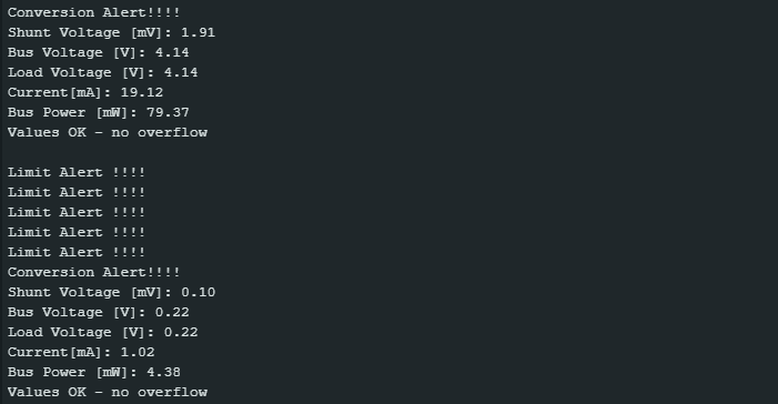
Output of Limit_And_Conversion_Alert.ino
For the following output, I waited for a regular output within the limits and then switched off my load. As a result, the set limit is permanently exceeded. Accordingly, the sketch outputs limit violations every second. Under the conditions set above, the sketch also issues a conversion ready alert approx. every 8 seconds:
Example 7: Continuous with alternative shunt size
A diligent contributor has added another feature to my library that allows you to use alternative shunts:
setResistorRange(0.005, 10.0)sets the resistance in ohms and the range in amperes. The maximum current Imax [A] = 0.0819175 / shuntSize (with shuntSize in Ohm) is the upper limit.setResistorRange(0.005)specifies the resistance, and the maximum range is calculated from this: Imax [A] = 0.0819175 / shuntSize with shuntSize in ohms.
The sketch works like the Continuous.ino sketch, but with the additional function. You can find it in the example sketches provided.
But aware: many INA226 modules with smaller shunts are scrap! I have written something about this here on Github.
#include <Wire.h>
#include <INA226_WE.h>
#define I2C_ADDRESS 0x40

/* There are several ways to create your INA226 object:
 * INA226_WE ina226 = INA226_WE(); -> uses I2C Address = 0x40 / Wire
 * INA226_WE ina226 = INA226_WE(I2C_ADDRESS);
 * INA226_WE ina226 = INA226_WE(&Wire); -> uses I2C_ADDRESS = 0x40, pass any Wire Object
 * INA226_WE ina226 = INA226_WE(&Wire, I2C_ADDRESS);
 */
INA226_WE ina226 = INA226_WE(I2C_ADDRESS);

void setup() {
  Serial.begin(115200);
  while(!Serial); // wait until serial comes up on Arduino Leonardo or MKR WiFi 1010
  Wire.begin();
  ina226.init();

  /* Set Number of measurements for shunt and bus voltage which shall be averaged
      * Mode *           * Number of samples *
    INA226_AVERAGE_1            1 (default)
    INA226_AVERAGE_4            4
    INA226_AVERAGE_16          16
    INA226_AVERAGE_64          64
    INA226_AVERAGE_128        128
    INA226_AVERAGE_256        256
    INA226_AVERAGE_512        512
    INA226_AVERAGE_1024      1024
    */
  //ina226.setAverage(INA226_AVERAGE_16); // choose mode and uncomment for change of default

  /* Set conversion time in microseconds
    One set of shunt and bus voltage conversion will take:
    number of samples to be averaged x conversion time x 2

    * Mode *                  * conversion time *
    INA226_CONV_TIME_140          140 µs
    INA226_CONV_TIME_204          204 µs
    INA226_CONV_TIME_332          332 µs
    INA226_CONV_TIME_588          588 µs
    INA226_CONV_TIME_1100         1.1 ms (default)
    INA226_CONV_TIME_2116       2.116 ms
    INA226_CONV_TIME_4156       4.156 ms
    INA226_CONV_TIME_8244       8.244 ms
  */
  //ina226.setConversionTime(INA226_CONV_TIME_1100); //choose conversion time and uncomment for change of default

  /* Set measure mode
    INA226_POWER_DOWN              - INA226 switched off
    INA226_TRIGGERED               - on demand, both current and bus voltage
    INA226_TRIGGERED_CURRENT_ONLY  - on demand, current only
    INA226_TRIGGERERD_BUS_ONLY     - on demand, bus voltage only
    INA226_CONTINUOUS              - continuous, both current and bus voltage (default)
    INA226_CONTINUOUS_CURRENT_ONLY - continuous, current only
    INA226_CONTINUOUS_BUS_ONLY     - continuous, bus voltage only
  */
  //ina226.setMeasureMode(INA226_CONTINUOUS); // choose mode and uncomment for change of default

  /* Set Resistor and Current Range
    Most INA226 modules use a 0.1 ohms shunt. If you have a board with a different shunt you need
    to set it with setResistorRange(). You pass the shunt value in ohms. The maximum current you
    can measure is Imax [A] = 0.0819175 / shuntSize.
    If you only expect currents lower than this Imax, you can also pass the expected Imax as a
    second parameter. The resolution is determined by the shunt register LSB (2.5 µV). However,
    passing a smaller Imax may result in a little higher resolution when the current is calculated.
  */
  //ina226.setResistorRange(0.005,10.0); // Example: shunt is 5 mOhm and expected Imax is 10 A
  ina226.setResistorRange(0.005); // Shunt is 5 mOhm, Imax is 16.3835 by default

  /* If the current values delivered by the INA226 differ by a constant factor
    from values obtained with calibrated equipment you can define a correction factor.
    Correction factor = current measured with calibrated device / current measured by INA226
    Be aware that Imax depends on the real shunt size.
  */
  // ina226.setCorrectionFactor(0.95);

  Serial.println("INA226 Current Sensor Example Sketch - Continuous");

  ina226.waitUntilConversionCompleted(); //if you comment this line the first data might be zero
}

void loop() {
  float shuntVoltage_mV = 0.0;
  float loadVoltage_V = 0.0;
  float busVoltage_V = 0.0;
  float current_mA = 0.0;
  float power_mW = 0.0;

  ina226.readAndClearFlags();
  shuntVoltage_mV = ina226.getShuntVoltage_mV();
  busVoltage_V = ina226.getBusVoltage_V();
  current_mA = ina226.getCurrent_mA();
  power_mW = ina226.getBusPower();
  loadVoltage_V  = busVoltage_V + (shuntVoltage_mV/1000);

  Serial.print("Shunt Voltage [mV]: "); Serial.println(shuntVoltage_mV);
  Serial.print("Bus Voltage [V]: "); Serial.println(busVoltage_V);
  Serial.print("Load Voltage [V]: "); Serial.println(loadVoltage_V);
  Serial.print("Current[mA]: "); Serial.println(current_mA);
  Serial.print("Bus Power [mW]: "); Serial.println(power_mW);
  if(!ina226.overflow){
    Serial.println("Values OK - no overflow");
  }
  else{
    Serial.println("Overflow! Choose higher current range");
  }
  Serial.println();

  delay(3000);
}
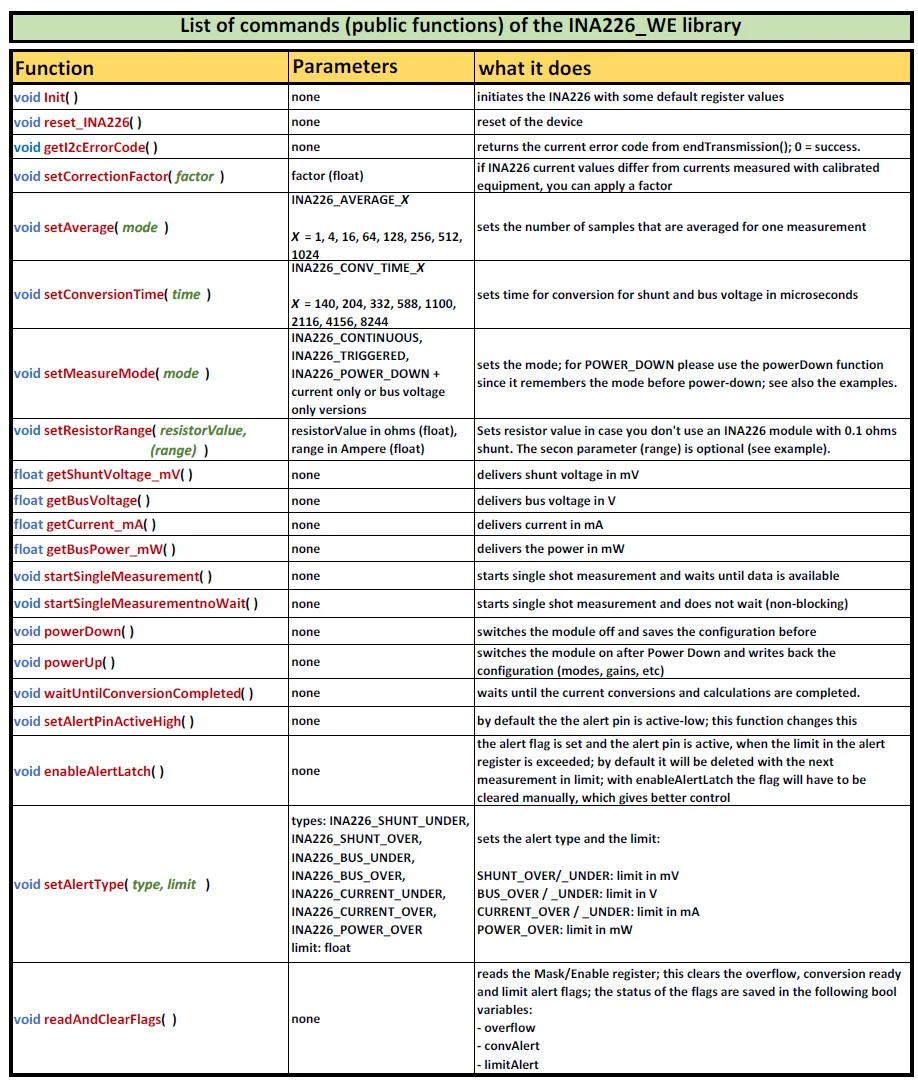
All functions at a glance
Here you can see all the functions at a glance. I also use the table for documentation on GitHub.
Details of the library and the registers of the INA226
If you still want to know more, you can now go a little deeper into the INA226 and the library.
The registers of the INA226
The INA226 has 10 registers, which is significantly more than the INA219 with its 6 registers. All registers are 16 bits.

Configuration Register

In the configuration register you can make basic settings:
- RST – Reset Bit: if it is set, a reset is triggered.
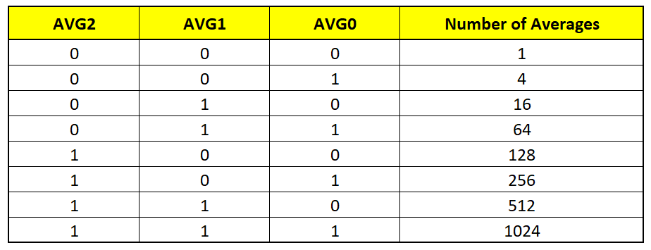
- AVGX – Average Bits: determine the number of individual measurements to be averaged.
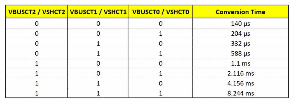
- VBUSCTX – Bus Voltage Conversion Time Bits: see table.
- VSHCTX – Shunt Voltage Conversion Time Bits: see table.
- I have made the simplification that only one conversion time can be selected, it then applies equally to the conversion of the bus and the shunt voltage.
- MODEX – MODE Bits: set the mode, see table.
Mask/Enable Register
I jump to the Mask/Enable Register because this is the other register for settings.

Bits 10 to 15 are used to activate the alarms:
- SOL / SUL: Shunt Voltage Over / Under Limit Alert
- BOL / BUL: Bus Voltage Over / Under Limit Alert
- POL: Power Over Limit Alert
- CNVR: Conversion Ready Alert
You can only activate one of the limit alerts. If you set several bits, then the highest applies. You can only activate the Conversion Ready Alarm in parallel.
In my library I have implemented an additional Current Over and Current Under Alarm. Internally, the SOL or SUL bit is set and the current limit is converted into a shunt voltage limit.
Further settings can be made with the APOL and the LEN bit:
- APOL: Alert Pin Polarity Bit – polarity of the alarm pin. Default is active-high (APOL = 0).
- LEN: Latch Enable Bit. By default, Latch is disabled (LEN = 0). This means that the alarm pin is deactivated and the alarm flag bit is deleted as soon as an OK measurement occurs (no limit exceeded). If LEN is set, the alarm pin remains activated and the alarm flag bit is set until the Mask/Enable register is read (
readAndClearFlags()).
The INA226 sets three flags, depending on the setting and measurement results:
- AFF: Alarm Function Flag – a limit has been exceeded.
- CVRF: Conversion Ready Flag – measurement results are available.
- OVF: Overflow Flag – a data register has overflowed.
The CVRF bit is deleted when the Mask/Enable Register is read or Configuration Register is described.
I programmed the function readAndClearFlags() to store the state of AFF, CVRF and OVF in the limitAlert, convAlert, and overflow variables.
Shunt Voltage Register
The Shunt Voltage Register contains the shunt voltage with an LSB (least significant bit) of 2.5 µV. In other words, the resolution of the shunt register is 2.5 µV per unit. Because the register has a sign bit, the value range of the shunt voltage is limited to:
![\[ shuntVoltageRange = \pm (2^{15}-1)\cdot 2,\!5 \text{\ µ\!V}=81,\!9175 \text{\ m\!V} \]](https://wolles-elektronikkiste.de/wp-content/ql-cache/quicklatex.com-900f9da2fae8af702f7d2a718381d224_l3.png "Rendered by QuickLaTeX.com")
By modifying the shunt you could theoretically change the maximum measurable current. However, you have no choice with the module, and you have to live with the 0.1 ohms. This results in a measuring range of +/- 819,175 mA for the current. In the case of INA219, on the other hand, the current LSB is 10 V. This means that the maximum measurable current is four times larger, but with a lower resolution.
Bus Voltage Register
The INA226 saves the result of the bus voltage conversion to the Bus Voltage Register. Only 15 bits are used by the Bus Voltage Register – the sign is always positive. The LSB is 1.25 mV, resulting in a maximum bus voltage of 40.96 V.
Current Register
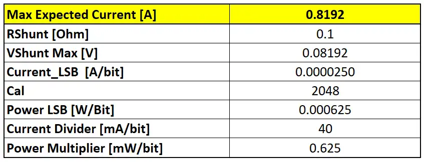
The INA226 stores the current calculated from the shunt voltage in the Current Register. This is where things get a little complicated, as a calibration factor CAL comes into play, which depends on the maximum expected current and the size of the shunt:
![\[ C\!AL = \frac{0,\!00512}{current\_LSB \cdot R_{Shunt}}\\ \]](https://wolles-elektronikkiste.de/wp-content/ql-cache/quicklatex.com-5dce216f77ae098325d4e9f9ef78e438_l3.png "Rendered by QuickLaTeX.com")
![\[ current\_LSB = \frac{maximum\ expected\ current }{2^{15}} \]](https://wolles-elektronikkiste.de/wp-content/ql-cache/quicklatex.com-f5adb5f3d787ce78b2cb681e4a102876_l3.png "Rendered by QuickLaTeX.com")
When calculating the calibration value, you start with the maximum expected current. For my library, I have selected 0.8192 amperes as the maximum. The formula for CAL would give an uncomfortable value for 0.819175, so I rounded up a little. The content of the Current Register is as follows:
![\[ currentRegister = \frac{shuntVoltageRegister \cdot C\!AL}{2048} \]](https://wolles-elektronikkiste.de/wp-content/ql-cache/quicklatex.com-571cb2ee0157a44d49f4994a8d584d87_l3.png "Rendered by QuickLaTeX.com")
In the end, you need to multiply the content of the Current Register by the Current_LSB to get the current.
The library automatically calculates the calibration factor for other shunt sizes.
Power Register
The Power Register contains the calculated power according to the following formula:
![\[ powerRegister = \frac{currentRegister \cdot busVoltageRegister}{20000} \]](https://wolles-elektronikkiste.de/wp-content/ql-cache/quicklatex.com-e96c68d05b861e474d8338f617270694_l3.png "Rendered by QuickLaTeX.com")
Finally, the power is the content of the Power Register, multiplied by the Power_LSB. The Power_LSB is (internally defined):
![\[ power\_LSB = current\_LSB\cdot 25 \]](https://wolles-elektronikkiste.de/wp-content/ql-cache/quicklatex.com-79f6a57c530595605db9ca8ab5bd0aa1_l3.png "Rendered by QuickLaTeX.com")
Calibration Register
The Calibration Register contains the above-mentioned calibration value.
Alert Limit Register
You enter the alarm limit in the Alert Limit Register. I have implemented this in such a way that you can pass the limits directly via the function setAlertType() in the respective designated units.
Calculation of calibration factors and LSBs
The library converts the content of the data registers into the desired units with the LSBs and other factors:
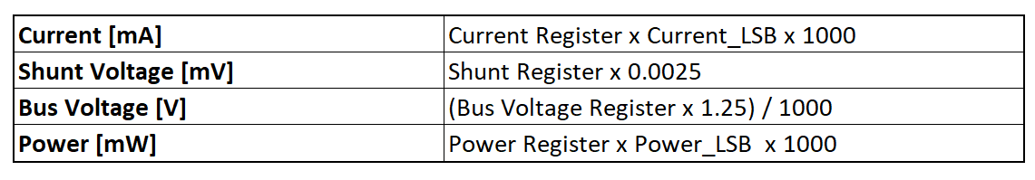
To get handy convenient factors, I introduced a Current Divider and a Power Multiplier:
![\[ current\ \text{[mA]}=\frac{currentRegister}{currentDivider}\ \ \\ \]](https://wolles-elektronikkiste.de/wp-content/ql-cache/quicklatex.com-3d3e50faaf91ca29b8514a0631305cff_l3.png "Rendered by QuickLaTeX.com")
![\[ \text{mit/with}\ \ currentDivider = \frac{1}{current\_LSB\cdot 1000} \]](https://wolles-elektronikkiste.de/wp-content/ql-cache/quicklatex.com-625b32cff27f5a00c93e8012f1d0e7cb_l3.png "Rendered by QuickLaTeX.com")
and
![\[ power\ \text{[mW]} = powerRegister \cdot powerMultiplier \]](https://wolles-elektronikkiste.de/wp-content/ql-cache/quicklatex.com-4464fd1ff75048a791110b27c92cae82_l3.png "Rendered by QuickLaTeX.com")
![\[ powerMultiplier = power\_LSB \cdot 1000 \]](https://wolles-elektronikkiste.de/wp-content/ql-cache/quicklatex.com-917822048443c9f48d79c1176aa3942c_l3.png "Rendered by QuickLaTeX.com")
I implemented the following values in the library:
Acknowledgement
The picture of the current meter is from the Free-Photos of Pixabay. I also found the alarm light from Alexey Hulsov and the display from the OpenClipart vectors on Pixabay.
Hello.
I connected the INA226 module to the ESP32. The resistance of the shunt used is 0.01 ohms.
When measuring, I constantly get the “Overload” event. I don’t understand what the problem is.
Can you tell me?
Initialization code:
void INA_Init()
{
ina226.init();
ina226.setAverage(AVERAGE_128);
ina226.setConversionTime(CONV_TIME_2116);
ina226.setResistorRange(0.01,7.0);
ina226.setCorrectionFactor(0.985);
ina226.waitUntilConversionCompleted();
}
Measurement code:
void Meashure()
{
ina226.readAndClearFlags();
if(ina226.overflow){Serial.print(“Overflow! Choose higher current range. I=”);Serial.println(ina226.getCurrent_mA());}
shuntVoltage_mV = ina226.getShuntVoltage_mV();
busVoltage_V = ina226.getBusVoltage_V();
Voltage = busVoltage_V + (shuntVoltage_mV/1000);
Current = ina226.getCurrent_mA();
}
The measurement process is performed by core No. 0
void Task0Code( void * parameter )
{
for (;;)
{
if (millis() – LastMeashure >= 100)
{
Meashure();
LastMeashure = millis();
}
vTaskDelay(10);
}
}
A warning in the port monitor:
Overflow! Choose higher current range. I=1358.86
Overflow! Choose higher current range. I=354.19
Overflow! Choose higher current range. I=2792.27
Overflow! Choose higher current range. I=1764.74
Overflow! Choose higher current range. I=751.53
Overflow! Choose higher current range. I=-374.27
Overflow! Choose higher current range. I=-374.27
Overflow! Choose higher current range. I=3141.11
Hi, I have tried to reproduce your settings and apply simple code. I also connected a module with an 0.01 ohms resistor (R010). This is the sketch I have uploaded to my ESP32:
#include <Wire.h>
#include <INA226_WE.h>
#define I2C_ADDRESS 0x40

INA226_WE ina226 = INA226_WE(I2C_ADDRESS);

void setup() {
  Serial.begin(115200);
  while(!Serial); // wait until serial comes up on Arduino Leonardo or MKR WiFi 1010
  Wire.begin();
  ina226.init();

  ina226.setAverage(INA226_AVERAGE_128); // choose mode and uncomment for change of default
  ina226.setConversionTime(INA226_CONV_TIME_2116); //choose conversion time and uncomment for change of default
  ina226.setMeasureMode(INA226_CONTINUOUS); // choose mode and uncomment for change of default
  ina226.setResistorRange(0.01, 7.0);
  ina226.setCorrectionFactor(1.0);
  ina226.waitUntilConversionCompleted(); //if you comment this line the first data might be zero
}

void loop() {
  float shuntVoltage_mV = 0.0;
  float loadVoltage_V = 0.0;
  float busVoltage_V = 0.0;
  float current_mA = 0.0;
  float power_mW = 0.0;

  ina226.readAndClearFlags();
  shuntVoltage_mV = ina226.getShuntVoltage_mV();
  busVoltage_V = ina226.getBusVoltage_V();
  current_mA = ina226.getCurrent_mA();
  power_mW = ina226.getBusPower();
  loadVoltage_V  = busVoltage_V + (shuntVoltage_mV/1000);

  Serial.print("Shunt Voltage [mV]: "); Serial.println(shuntVoltage_mV);
  Serial.print("Bus Voltage [V]: "); Serial.println(busVoltage_V);
  Serial.print("Load Voltage [V]: "); Serial.println(loadVoltage_V);
  Serial.print("Current[mA]: "); Serial.println(current_mA);
  Serial.print("Bus Power [mW]: "); Serial.println(power_mW);
  if(!ina226.overflow){
    Serial.println("Values OK - no overflow");
  }
  else{
    Serial.println("Overflow! Choose higher current range");
  }
  Serial.println();

  delay(1000);
}
The code works without issues. I don’t get overflows. Can you try exactly the same code?
And what kind of module do you use? If you have one of the red ones I have described here:
https://github.com/wollewald/INA226_WE?tab=readme-ov-file#quality-of-small-shunt-ina226-modules
then you need to apply the current to the big connectors.
What current values are you measuring? At what voltage?
I just applied the 3.3 volts and a small load of around 50 mA. What have you applied? The output you shared seem to be random numbers. Or is it AC? Do you have a stable DC load with known current consumption you can test?
These are the values of the cyclic charge -discharge current of the battery at a voltage of 14.6 V
I have tried ~1 A / 5 V and it works fine for me. So not sure what’s wrong at your end. If you think the issue is related to my library, then I suggest trying another one. There are several available. Not all allow setting a different shunt, but this is no problem. Just multiply the current accordingly.
And you could still try the sketch I have shown in my first reply. A few days ago I had published an update (1.4.0) of my library (which should have no effect on the issue you face). I have updated the sketch above so that it works with the new version.
Thank you for your answers.
I’ll try your sketch and the new version of the library. But I think the problem lies in the module itself.
Hi Wolfgang, firstly thank you for providing your INA226 library. For my application, I do not need to measure bus voltage, so I want to set the measurement mode to continuous shunt voltage only (101). Is there any way that I can implement this? Will simply adding the mode into the INA226_MEASURE_MODE enum work? Thank you
Hi Albert,
I can implement this, but it will take time. In the meantime you can modify my library. It is the enum INA226_MEASURE_MODE. The first bit (counting from right to left) is for the shunt measurement (1=active), the second is for bus measurement (1=active), and the third bit is for continous vs. single shot (1=continuous).
So as you rightly say 101 would be the correct setting. So just go into the cpp file, line 57 and 61, and change 0b00000111 to 0b00000101. That should be the easiest way. Or you try and extend the enum. It should also work. I put this on my to-do list, but it is quite long.
I’ve added an entry into the enum and it seems to work (bus voltage reading became 0). I appreciate your detailed response and confirmation. Cheers!
I used the exaxtly same circuit diagram in this page.My Vbus is 5V and i used series of different resistor for a load.Then I opened Continuous_With_Resistor_Value.ino example and upload it to Nano as it is without any minor changes.My shunt resistor is 5miliOhm.(0.005)
Load : 216 Ohm
Multimeter Value [mA]: 22.44
18:56:30.441 -> Shunt Voltage [mV]: 0.64
18:56:30.441 -> Bus Voltage [V]: 4.85
18:56:30.486 -> Load Voltage [V]: 4.85
18:56:30.486 -> Current[mA]: 127.56
18:56:30.486 -> Bus Power [mW]: 610.35
18:56:30.486 -> Values OK – no overflow
————————————————-
Load : 385 Ohm
Multimeter Value [mA]: 12.80
19:06:01.107 -> Shunt Voltage [mV]: 0.35
19:06:01.107 -> Bus Voltage [V]: 4.92
19:06:01.140 -> Load Voltage [V]: 4.92
19:06:01.140 -> Current[mA]: 71.11
19:06:01.140 -> Bus Power [mW]: 350.95
19:06:01.140 -> Values OK – no overflow
————————————————
Load : 4,62 KOhm
Multimeter Value [mA]: 1.09
19:09:34.760 -> Shunt Voltage [mV]: 0.03
19:09:34.760 -> Bus Voltage [V]: 5.02
19:09:34.794 -> Load Voltage [V]: 5.02
19:09:34.794 -> Current[mA]: 5.49
19:09:34.794 -> Bus Power [mW]: 22.89
19:09:34.794 -> Values OK – no overflow
And what have you chosen as maximum expected current?
ina226.setResistorRange(0.005,?????);
As i said mate I didn’t touch it : ( ina226.setResistorRange(0.005,10.0); )
I replaced the shunt with a different 3W smd one.Its resistance can be read on as R005 and nothing changed.Then again i did replaced it with wire type shunt resistor which i had previous known to be the 10miliOhm this time.Accuracy improved this time but it still had like 50 error margin.Thank you for giving your time.Much appriciated
Your multimeter values seem to be correct and the INA226 are 5 – 5.5 times too high. I have just tested a module with an R002 shunt and it works fine with the Continuous_With_Resistor_Value.ino sketch. Therefore, I can say that there is no issue with the library. It seems like the shunt is smaller than 5 milliohms. Maybe you can double-check. The other way round would be easier to explain, e.g. by additional resistance because of bad contacts. No idea why the shunt could differ so much.
I am writing this just to let you know that all the modules in my possessions turned out to be counterfeit.Thank you indeed for quick responces.Cheers
Thanks for letting me know. I am happy to hear you found the problem, but how disappointing for you to spend so much time! Can you share how you found out? Could be useful for other readers who experience similar issues. All these counterfeits are really annoying.
Hi,
Thank you for the work you put in this library.I have a problem with measurement of ampere.I changed the shunt resistor with a value of 5miliOhmon my module.Then I opened Continuous_With_Resistor_Value.ino example and made necessary changes.Even so I can’t get a correct reading of ampere.My serial connected multimeter shows 20 miliamp but I get 123 miliamp with the module.I am stuck at this point.
Any help is much appriciated.
Hi, is this deviation linear? I.e. if you measure 40 milliamps (according to your multimeter), do you then measure something in the range of 246 milliamps with the module (a constant factor)? Or 143 milliamps (parallel shift)?
It may help to understand the reason if you vary the current, and could share the results you measure with the module and with your multimeter. Also, the values without any current would be helpful.
And which expected current did you choose?
Thanks for such an extensive example for the INA226.
I have loaded the Continuous sketch and uploaded it to an esp32. however, when I open the serial monitor i don’t get any feedback. The screen is blank, no error messages no read outs from the chip.
any ideas what could be causing the program to lockup.
Maybe wrong baud rate? Or the INA226 is not connected and the message “Failed to init INA226. Check your wiring.” is not displayed because it takes time until Serial is set up. You should see it if you reset the ESP32 or if you add a delay(2000) at the begin of setup(). Then we would have to answer the question of why it is not connected. But one step after the other.
Hello.
I tryed to check the current from 200 uA to 400mA, change shunt resistor (0.1 ~0.39 ohm)
( Test Supply Voltage : 11 ~ 14 Volt)
I have a questions about Shunt Voltage is required minunum value?
If I want to check 200uA of Current, Which shunt resistor value I have to condier?
Please give me a advice .
Thanks. in advance.
Hi, the shunt voltage register has a range from -81.920 to +81.9175 mV. The resolution is 2.5 µV. The maximum voltage you are going to measure limits the maximum shunt size. To use the full resolution at 400 mA, the shunt size would be R = U_max/I = 0.0819175 / 0.4 = ~0.2048… ohms. With this, your resolution for the current would be 0.4 A / (2^15-1) = ~12.2 µA. So, if you got a result of 200 µA, it would be in fact 200 µA +/-12.2 µA.
But this is the ideal, purely calculatory view. In reality, you might have some noise, and there might be unwanted resistances in your circuit, in particular if you try things on a breadboard. To reduce noise, you should use a stable power supply, solder contacts, choose a long conversion time and average many results.
I’m trying to use this library with Raspberry pi pico. The problem is that initialization fails. I found if after I saw that Init() function returns Boolean value. Now I guess that the I2C port may be incorrect. How can I check or set the I2C port?
You can use an I2C scanner sketch to check which I2C addresses are available:
https://wolles-elektronikkiste.de/en/i2c-scanner?lang=en
If none is available, then check your wiring and maybe try adding pullup resistors to the I2C lines.
I haven’t read through all the earlier comment – sorry. But I can’t see what the ‘Range’ parameter does in the ‘setresistorrange()’ function.
In the library header file I can’t find the function.
If we define the resistor, the current is defined by the shunt voltage so I’m at a loss.
What am I missing here.
Thanks
The maximum current you can measure is indeed limited by the shunt size:
maxCurrent = 81.9175 mV / shuntSize.
Since the LSB of the current register is:
currentLSB = maxExpectedCurrent/2^15
…there is a higher resolution if you choose a maximum current lower than the theoretical maximum current. But to be honest, this is just calculatory resolution. In the end it’s the resolution of the shunt register and the shunt size which limits the resolution.
Hello Wolfgang, guten Tag Herr Ewald,
Thank you for your work on the libraries!!!
I have a question about the INA219 and INA226. I have tried them both with your libraries and with two different ESP32-S3 LCD/touchscreen boards. The Waveshare 4.3″ and the WT32-SC01 plus.
On the first board I have a full i2c bus, on the second only the INA (0x40).
On both setups I use LVGL. On the WT32-SC01 plus combined with LovyanGFX.
Now what happens is this: only when I completely comment out the graphics part I get readings from the INA’s. As soon as I want to use graphics, all readings are zero. It looks like the LVGL is the reason for this. Did you encounter this at any point and/or am I doing something stupid??
Any help or hint is highly appreciated…
(I tried to add some code but got a spam message for some reason.)
Update:
Indeed, I was stupid. I just realised that there is a different i2c bus for the touchscreen!! That bus took over and the INA’s got put out of business.
I created a Wire1 with the extended IO and the problems are solved!!
Thanks anyway!!
Hi Ewald,
Thanks for this great article!
I would like to measure the current of a system, no need for the power.
Is it correct to connect the system GND to IN- , and system positive side to VBS pin?
Then I though to monitor voltage with “busVoltage_V = ina226.getBusVoltage_V();”.
Is it a requirement to have a common ground between ESP8266 side, and the system GND?
To provide additional background, I have an doorbell, connected to a inter-phone. The doorbell receive 5.2V when idle, and 18V when active. So I would like to monitor voltage, and send notification to my phone when someone press the doorbell.
Hi Adrien, your bus circuit and the INA226 need to have the same GND, otherwise the INA226 would not be able to determine the bus voltage. The reference is the GND of the INA226. So, if the bus GND and the INA226 GND would be different, the measured values would be meaningless. And your microcontroller and the INA226 need have the same GND because it is the reference for the I2C communication.
IN- shall only be connected to GND if you choose the low side configuration, i.e. the load is on the positive power supply side and the INA 226 is on the GND side: V+ – Load+ – Load- – In+ – IN+ – GND. In that case you would connect VBUS to V+.
Hope this helps!
Regards, Wolfgang
Thank you for clarification. Sorry, I’m new to this topic, so just to be sure, let’s assume I want to monitor the voltage of a 3.7V battery, without any actual load, just the battery.
Should I connect
INA226 IN- —–> Battery Negative
INA226 IN+ —–> Battery Positive
or can I use following
INA226 IN- —–> Battery Negative
INA226 VBUS —–> Battery Positive
and monitor with ina226.getBusVoltage_V() ?
By the way, on ESP8266 INA226 side, I have
GPIO4 (SDA) —-> SDA
GPIO5 (SCL) —-> SCL
GND —-> GND
3.3V —-> VCC
Maybe you have not yet understood what the INA226 does. It is primarily a current sensor. The current flows through IN+ to IN-
Between IN+ and IN- there is a resistor (shunt). The voltage dop is measured and from that the INA226 calculates the current. This has nothing to do with the voltage of your battery. However, in addition to that feature the INA226 is able to measure the bus voltage in order to calculate the power from that (current x voltage). If you only want to use this feature then just connect GND to battery minus and VBUS to battery plus. But in this case I would not use an INA226 but a simple A/D converter like the ADS1115.
Regards, Wolfgang
What about measuring current of a square signal (+30 -30 volt) with this sensor, which is applied to a 2k load? how can I handle this?
IN+ and IN- can have a negative differential voltage, but both IN+ and IN- shall not be connected to a voltage of smaller than -0.3V vs. GND. Therefore, there is no easy solution to your problem.
Hi.
You have an error in your code: you enable interrupt 0 and disable interrupt 2.
…
attachInterrupt(digitalPinToInterrupt(interruptPin), alert, FALLING);
…
void alert(){
event = true;
detachInterrupt(2);
}
Oops, yes, forgot the digitalPinToInterrup(interruptPin) in the detachInterrupt() functions – thanks!
Hi,
First of, thank you so much for this library !
I am using a INA226 module from aliexpress with a R010 (0.01 ohm) shunt resistor (rated 20A, but I only need to measure up to 6A).
My goal is to measure a 12V brushed DC motor current consumption in order to determine the resistance of its load.
I setup the resistor with
ina226.setResistorRange(0.01, 10.0);
which seems to be working fine as the measurments without load on the motor are close to what the lab power supply and a DMM in series show.
My problem is that once I apply some resistance on the output of the motor, the current increases, and once it reaches ~500mA (sometimes 800mA depending on the conversion time/average), the getCurrent_mA only returns 0 (same for power), even after the load is back to nominal (~230mA). It works again after resetting the esp32
What I noticed in my tests is that the conv alert is usually oscillating between 0 and 1 before the getCurrent_mA stops working, and stays at 1 afterwards.
On the other hand, the shunt voltage seems to keep reporting a value, but when plotting the shunt voltage value, it seems that before the error, it is quite smooth (with the average), and after the error, it is very irregular.
I am not sure whether this could be related to the lib or a faulty module, or maybe a mistunderstanding on my side.
Any input would be welcome
Hi,
not sure what the reason could be. I have not seen this issue before. I doubt that you have a faulty module because then I would expect problems not only above a certain current limit. Do you use the sketch “Continuous_With_Resistor_Value.ino”? Did you apply any changes apart from the setting of the resistor and range? If yes, can you send me the code (wolfgang.ewald@wolles-elektronikkiste.de).
To check whether your module works you could try an alternative library: https://github.com/Zanduino/INA, example sketch DisplayReadings.ino.
And which microcontroller board are you using?
Regards, Wolfgang
Thank you for your reply,
It was based on the continuous_with_resistor_value with a few tweaks,
but I tried with Zanduino/INA just now and I can see the exact same behavior.
So the issue is definitely not in the library
I am using an ESP32 devkit (With CH340C/USBC) from aliexpress, powered via USB and powering the INA module from the 3.3V output.
Here is an image with plots showing what happens :
https://imgur.com/a/COjCNj9
I will order a different INA module to see if it behaves differently. In the mean time, I am using the shunt voltage divided by the resistance, which is good enough I guess
Regards,
Julien
Hi Julien,
this is weird! In particular, I don’t understand that you still measure “something” as shunt voltage, but 0 as current. Since the current is just calculated by the INA226 you should also get current values. I am really curious if a different module will work, even if the issue is not related to my library. Good luck!
Regards, Wolfgang
Thank you for the great article!
Today I ran the first sketch using a INA226 breakout boards with R100 shunt. I hooked it up to a ESP8266 running on 3.3V.
The current results are great.
However, voltage is always around 20V, regardless of true input voltage. The reading doesn’t change even when I double or cut in half the input voltage.
Obviously I must be doing something really dumb. I double-checked the wiring and tested with a completely different INA226 board with R010 resistor.
With both boards, current reading is perfect (after adding the serResistorRange() call in the R010 case). Voltage reading however is always at around 20V fixed, with varying real loads and voltages.
What could I be doing wrong? Many thanks!
Do the module and the load have a common GND? That’s the only spontaneous idea I have.
Hi again,
I’m having a hard time understanding how exactly “using the smallest allowable Current_LSB” gives the highest resolution for the Current Register.
By Ohm’s law, the current resolution ultimately depends on the shunt voltage LSB, which is 2.5uV (fixed value), and the shunt resistor value. In other words, the current will increment in steps of shuntVoltage_LSB / shunt resistor. So for a 0.1Ohms resistor, the minimum detected current will be 25uA independently of whatever the “max expected current” is programmed.
I’m sure there is something wrong with my understanding.
So, anyway, for this module, if max expected current is only 0.2A, how is the current resolution increased? What will be the lowest measurable current in theory in that case?
Thanks
You are right, the ultimate limiting factor for the resolution of the measured current is the resolution of the shunt voltage register in combination with the shunt size. And your calculation is correct, 25 µA is the maximum resolution. With this, the maximum current is 0.8192 Ampere. Therefore, I have to admit that when using the 0.1 ohms shunt, there is no benefit in changing to the 0.4 amps range. I should take the option out. However, the calculations in the article shall show how to calculate the calibration factor.
Basically, one doesn’t rally need the current register. You can calculate the current yourself without all this stuff.
Hi, I just wanted to add I took out the range setting. It’s now 0.8192 volts. The reason why I had implemented the two ranges is simply that I first wrote a similar library for the INA219 where the ranges really increase the resolution. I just took this over. So, thanks for the comment. A new version 1.2.9 of the lib is now published on GitHub.
Best wishes, Wolfgang
Hello,
I’m noticing with all INA226 libraries a measurement error on the Bus voltage.
Here’s a table with the measured values:
Set (V) Max sensor reading(V)
0 0.03
0.5 0.51
1 1.02
1.5 1.53
2 2.03
3 3.05
4 4.06
5 5.08
10 10.15
15 15.23
20 20.3
25 25.38
30 30.46
35 35.53
ESP32 powering the device at 3.3V. Powering the sensor from an external power supply with voltages between 1.8V and 3.3V barely affect the readings (10mV max difference between 1.8V vs 3.3V supply).
The applied voltage on the Vbus pin is generated with a precise Riden RD6006P power supply and was checked with an Uni-T UT61D+ multimeter.
As you can see in the table, it’s almost a +1.5% constant error;
Have you experienced this with your sensor module? Any ideas what could be causing this?
Thanks
Hi Alejandro,
this is stange. I have just tried and have found a deviation of less than 0.1% between VBUS measured by the INA226 and my multimeter. I tested at 3.3 and 4.6 Volts. Have you tried different modules?
Hey, thanks for trying it out.
Unfortunately, I only have this module I got from AliExpress: https://ibb.co/CmNPTyK
It may be a fake chip, or just a damaged unit…
hi
Thank you for this Education
I have problem with uploading code in Arduino UNO
I downloaded your Code and library and try to upload this in to arduino UNO board
but Appears this error
Arduino: 1.8.19 (Windows 10), Board: “Arduino Uno”
Sketch uses 6908 bytes (21%) of program storage space. Maximum is 32256 bytes.
Global variables use 650 bytes (31%) of dynamic memory, leaving 1398 bytes for local variables. Maximum is 2048 bytes.
avrdude: verification error, first mismatch at byte 0x0800
0xff != 0x80
avrdude: verification error; content mismatch
avrdude: verification error; content mismatch
please help me to solve this problem
thank you
Parsa
This does not sound like an issue with my code, but something more general. Can you try to upload any other sketch like e.g. the blink sketch from the examples of the Arduino IDE? Does this work without failure?
Wolfgang
Dear Sir,
Thankyou for the reply. I am waiting for the 30A shunt to arrive from AliExpress. The one I have is 10A shunt. I will post my result here once the shunt arrives.
regards
sajeev
Dear Sir,
Thank you for the article. I am a newbie and don’t have much experience in electronics and poor in math. I am planning to use you continues.ino to measure the parasitic drain from a 12v car battery . I would like to measure with 1mA resolution form 0 – 30A range .Please advise what value of shunt resistor i should choose? I have one of those heavy shunts from aliexpress 75mv/A lying around. What is the range that can be measured with R100 shunt resistor originally installed on the module and what is the resolution>
regards
Sajeev
Hi, with the R100 (= 0.1 ohms) is 800 mA. The limiting factor is the shunt register. The current is calculated from the value in this register. The maximum shunt voltage is 81.9175 mV. If your maximum current is 30 amperes, the maximum shunt size is:
U = R * I (Ohm’s law)
R = U / I = 0.081975 / 30 = 0,0027325 Ohms
Are you shure that your shunt provides 75 mV / A? Usually these shunts provide 75 mV at the max. current. E.g. you can buy a 30A / 75 mV shunt. That would be a perfect fit because you would use almost the whole range of the module (75 mV vs. 81.975 mV).
https://www.aliexpress.com/item/4000064064917.html?spm=a2g0o.productlist.main.1.5c12612fsS9AkR&algo_pvid=bb39660a-d08c-4e03-9ae2-5ecadc648481&algo_exp_id=bb39660a-d08c-4e03-9ae2-5ecadc648481-0&pdp_npi=4%40dis%21EUR%212.50%212.38%21%21%212.62%21%21%4021038eda16941880101944247e5c90%2110000000289433251%21sea%21DE%21897358883%21S&curPageLogUid=Gg5Nz6w0VHWz
Be careful: 12V is not dangerous, but with 30A you can easily cause fire if your wires are too thin or the shunt is not correct!
And one additional comment: If you ony want to measure parasitic drain, then 30 amperes seems to very high.
Good luck, Wolfgang
Dear Sir,
Thankyou for the quick reply. I chose 30A range as the modules in the car wakes up intermittently and currant draw spikes to 10-15A and then drops to mA range. If i prepare the circuit only for mA these spikes may fry the 226board. I already ordered the aliexpress 30A shunt you linked above. What resolution can i expect? will I be able to measure 1mA with this 30A shunt?
Regards
Sajeev
Dear Sajeev, the values in the shunt register are the basis of all calculations. The resolution is 2.5 µV per bit and the register is +/-2^15 = +/-32768 which is roughly +/-82 mA. Your shunt delivers 75 mV at 30 A. That means you use 75/82 * 100 = ~91.5% of the range, which means ~ +/- 30000 bits in the shunt register. So, resolution is roughly 1 mA, so what you are looking for. However, this is an ideal value which does not consider any noise. To really get as near as possible to that resolution, you should average many values. I think the resolution will be in reality more in the range of few milliamps than 1 milliamp. But I would say, just try.
Regards, Wolfgang
Hello,
I am new in this arduino world. I have done a small proyect using your library. But I have the following problem. I have a circuit with two resistors in series, being the total sum of 1330 ohms, a LED and i am powering the proyect with 3.3V. Theorically the current i should get is 3.3/1330=0.00254A=2.54mA but i am getting a current of 1.11mA
Any idea of what could be wrong?
Thank you in advanced
Hi, you have two resistors and the LED in series, right? The LED also has a resistance. But its resistance depends on the current, so it’s a problem for the calculation. To just check if you get correct results, you could remove the LED. Do you then measure the calculated current?
Yes. I did what you said and now the result makes much more sense. I thought we could ignore the LED’s resistance but it seems to be high enough to take it into account.
Thank you for the post, it’s very useful for everyone that is trying to understand INA226.
Hi,
das ist sehr gut erklärt. Aber ich möchte 2 oder 3 ina226 zusammen schalten und aus lesen. Leider bekomme ich es nicht hin. Gibt es so etwas im Netz oder wo finde ich eine Erklärung?
Gruß
Lorenz
Hi,
hier bist du auf der englischen Seite gelandet. Das gibt’s auch auf Deutsch. Aber kein Problem.
Erst einmal muss jeder INA226 hardwarseitig seine eigene I2C Adresse bekommen. Das habe ich im Beitrag erklärt. Du verbindest dann alle SCL Pins und alle SDA Pins. Über die I2C Adresse wissen die Module, welches von ihnen angesprochen wird.
Dann erzeugst für jeden INA226 ein eigenes Objekt:
INA226_WE ina226_1(0x40);
INA226_WE ina226_2(0x41);
INA226_WE ina226_3(0x44);
Dann musst du für jedes einzelne die Einstellungen vornehmen:
ina226_1.init();
ina226_2.init();
ina226_3.init();
ina226_1.setMeasureMode();
ina226_2.setMeasureMode();
….usw.
Und dann in loop():
shuntVoltage_mV = ina226_1.getShuntVoltage_mV();
busVoltage_V = ina226_1.getBusVoltage_V();
…usw und dann zeigst du die Werte auf dem seriellen Monitor und gehst zum nächsten INA226:
shuntVoltage_mV = ina226_2.getShuntVoltage_mV();
busVoltage_V = ina226_2.getBusVoltage_V();
…..und dasselbe für Nr. 3. .
Ein bisschen verschwenderischer wäre die Variante:
shuntVoltage_mV_1 = 0.0; shuntVoltage_mV_2 = 0.0; shuntVoltage_mV_3 = 0.0;
shuntVoltage_mV_1 = ina226_1.getShuntVoltage_mV();
shuntVoltage_mV_2 = ina226_2.getShuntVoltage_mV();
…usw..
Prinzip klar geworden?
VG, Wolfgang
Sorry hab ich nicht gesehen. Hat sich überschnitten. Danke für die schnelle Antwort. Ich hab keinen Fehler gefunden. Bin aber auch kein Profi.
Lorenz
Der Fehler ist ganz einfach – du fragst in loop() immer denselben INA226 ab, also z.B:
shuntVoltage_mV1 = ina226.getShuntVoltage_mV();
und dann:
shuntVoltage_mV2 = ina226.getShuntVoltage_mV();
Stattdessen müsste es heißen:
shuntVoltage_mV2 = ina227.getShuntVoltage_mV();
Hallo,
danke. Manchmal sieht man den Wald vor Bäume nicht.
Gruß
Lorenz
Hallo Wolfgang,
so funktioniert es . Hab noch Zeilen verschoben. Falls es wer brauchen kann.
#include
#include
#define I2C_ADDRESS_1 0x44
INA226_WE ina226 = INA226_WE(I2C_ADDRESS_1);
#define I2C_ADDRESS_2 0x40
INA226_WE ina227 = INA226_WE(I2C_ADDRESS_2);
// INA226_WE ina226 = INA226_WE(); // Alternative: sets default address 0x40
void setup() {
Wire.begin();
Serial.begin(9600);
ina226.init();
ina226.waitUntilConversionCompleted();
ina227.init();
ina227.waitUntilConversionCompleted();
// ina226.setCorrectionFactor(0.95);
//Serial.println(“INA226 Current Sensor Example Sketch – Continuous”);
}
void loop() {
float shuntVoltage_mV1 = 0.0;
float loadVoltage_V1 = 0.0;
float busVoltage_V1 = 0.0;
float current_mA1 = 0.0;
float power_mW1 = 0.0;
ina226.readAndClearFlags();
shuntVoltage_mV1 = ina226.getShuntVoltage_mV();
busVoltage_V1 = ina226.getBusVoltage_V();
current_mA1 = ina226.getCurrent_mA();
power_mW1 = ina226.getBusPower();
loadVoltage_V1 = busVoltage_V1 + (shuntVoltage_mV1/1000);
Serial.print(“Shunt1 Voltage [mV]: “); Serial.println(shuntVoltage_mV1);
Serial.print(“Bus1 Voltage [V]: “); Serial.println(busVoltage_V1);
Serial.print(“Load1 Voltage [V]: “); Serial.println(loadVoltage_V1);
Serial.print(“Current1[mA]: “); Serial.println(current_mA1);
Serial.print(“Bus Power1 [mW]: “); Serial.println(power_mW1);
if(!ina226.overflow){
Serial.println(“Values OK – no overflow”);
}
else{
Serial.println(“Overflow! Choose higher current range”);
}
Serial.println();
/*—————— second one ——————-*/
float shuntVoltage_mV2 = 0.0;
float loadVoltage_V2 = 0.0;
float busVoltage_V2 = 0.0;
float current_mA2 = 0.0;
float power_mW2 = 0.0;
ina227.readAndClearFlags();
shuntVoltage_mV2 = ina227.getShuntVoltage_mV();
busVoltage_V2 = ina227.getBusVoltage_V();
current_mA2 = ina227.getCurrent_mA();
power_mW2 = ina227.getBusPower();
loadVoltage_V2 = busVoltage_V2 + (shuntVoltage_mV2/1000);
Serial.print(“Shunt2 Voltage [mV]: “); Serial.println(shuntVoltage_mV2);
Serial.print(“Bus2 Voltage [V]: “); Serial.println(busVoltage_V2);
Serial.print(“Load2 Voltage [V]: “); Serial.println(loadVoltage_V2);
Serial.print(“Current2[mA]: “); Serial.println(current_mA2);
Serial.print(“Bus2 Power [mW]: “); Serial.println(power_mW2);
if(!ina227.overflow){
Serial.println(“Values OK – no overflow”);
}
else{
Serial.println(“Overflow! Choose higher current range”);
}
Serial.println();
delay(2000);
}
Gruß
Lorenz
Hallo,
hier der Code
#include
#include
#define I2C_ADDRESS_1 0x44
#define I2C_ADDRESS_2 0x40
// const int I2C_ADDRESS_1 = 0x44;
// const int I2C_ADDRESS_2 = 0x40;
INA226_WE ina226 = INA226_WE(I2C_ADDRESS_1);
INA226_WE ina227 = INA226_WE(I2C_ADDRESS_2);
// INA226_WE ina226 = INA226_WE(); // Alternative: sets default address 0x40
void setup() {
Serial.begin(9600);
Wire.begin();
ina226.init();
ina227.init();
// ina226.setCorrectionFactor(0.95);
Serial.println(“INA226 Current Sensor Example Sketch – Continuous”);
ina226.waitUntilConversionCompleted();
ina227.waitUntilConversionCompleted();
}
void loop() {
float shuntVoltage_mV1 = 0.0;
float loadVoltage_V1 = 0.0;
float busVoltage_V1 = 0.0;
float current_mA1 = 0.0;
float power_mW1 = 0.0;
ina226.readAndClearFlags();
shuntVoltage_mV1 = ina226.getShuntVoltage_mV();
busVoltage_V1 = ina226.getBusVoltage_V();
current_mA1 = ina226.getCurrent_mA();
power_mW1 = ina226.getBusPower();
loadVoltage_V1 = busVoltage_V1 + (shuntVoltage_mV1/1000);
Serial.print(“Shunt1 Voltage [mV]: “); Serial.println(shuntVoltage_mV1);
Serial.print(“Bus1 Voltage [V]: “); Serial.println(busVoltage_V1);
Serial.print(“Load1 Voltage [V]: “); Serial.println(loadVoltage_V1);
Serial.print(“Current1[mA]: “); Serial.println(current_mA1);
Serial.print(“Bus Power1 [mW]: “); Serial.println(power_mW1);
if(!ina226.overflow){
Serial.println(“Values OK – no overflow”);
}
else{
Serial.println(“Overflow! Choose higher current range”);
}
Serial.println();
/*—————— second one ——————-*/
float shuntVoltage_mV2 = 0.0;
float loadVoltage_V2 = 0.0;
float busVoltage_V2 = 0.0;
float current_mA2 = 0.0;
float power_mW2 = 0.0;
ina227.readAndClearFlags();
shuntVoltage_mV2 = ina226.getShuntVoltage_mV();
busVoltage_V2 = ina226.getBusVoltage_V();
current_mA2 = ina226.getCurrent_mA();
power_mW2 = ina226.getBusPower();
loadVoltage_V2 = busVoltage_V2 + (shuntVoltage_mV2/1000);
Serial.print(“Shunt2 Voltage [mV]: “); Serial.println(shuntVoltage_mV2);
Serial.print(“Bus2 Voltage [V]: “); Serial.println(busVoltage_V2);
Serial.print(“Load2 Voltage [V]: “); Serial.println(loadVoltage_V2);
Serial.print(“Current2[mA]: “); Serial.println(current_mA2);
Serial.print(“Bus2 Power [mW]: “); Serial.println(power_mW2);
if(!ina227.overflow){
Serial.println(“Values OK – no overflow”);
}
else{
Serial.println(“Overflow! Choose higher current range”);
}
Serial.println();
delay(2000);
}
Einzeln funktioniert es. Mit Beiden bekomme ich auf beiden Anzeigen die gleichen Daten.
Lorenz
Hello,
Thanks for great articles!
I have one question: what is the lowest current IN226 can measure? In <400mA range.
I’ve checked INA226 specs, but it’s not clear for me(
Hi, the limiting factor the shunt voltage register, which has a resolution of 2.5 microvolts per bit. In the 400mA range this translates into a resolution of 0.0122 mA. So, if your current range is e.g. 0 to 1.22 mA there would be 100 different values you cold measure. However there will also be some noise. I would say for reliable measurements you need a few milliamps.
Danke schön!
Thx for the article! I want to use the better module with r002 shunt. I need to run ~12v 9A through it, did you know if this will work or does it get to hot?
The bus voltage (12V) doesn’t matter. Only the current and the shunt size is relevant. The power dissipation across the resistor is:
P = U * I = R * I * I = 0.002 * 9 * 9 = 0.162 watt.
Most modules have 2512 resistors, which can be used up to 1 watt. So you should be still on the very safe side.
You can find the different sizes and maximum power dissipations of SMD resistors here, for example:
https://eepower.com/resistor-guide/resistor-standards-and-codes/resistor-sizes-and-packages/#
Thx for answering. Yes that make sense. The link to the smd resistors guide is very helpful.
Is it possible to connect two of these modules in series with two batteries? Because I want each module to measure the voltage of each battery? I didn’t find a way to do that
Thank you for help
Hi,
a pedantic comment: you measure the current of the battery, not the voltage.
Using two INA226 is no problem as long as the module has address pins. You can use up to four modules. Even more are possible, but that would lead to far.
I have described in the article how to change the I2C address. So let’s assume one has the address 0x40 and the other one 0x41. Then you just create two objects like this:
#define I2C_ADDRESS_1 0x40
#define I2C_ADDRESS_2 0x41
INA226_WE ina226_1 = INA226_WE(ICM20948_ADDR_1)
INA226_WE ina226_2 = INA226_WE(ICM20948_ADDR_2)
Then you can use both on a single I2C bus.
Regards, Wolfgang
hello dear Wolfgang,
first, thank you for sharing your experience and helping people with this module!
I ‘m currently prototyping my final student work (a little lab bench powersupply).
during the prototyping, the 800mA max current range was enough some experimentations …
But now, since each output of my lab power supply must deliver max 3A, i swapped the shunt resistor with a 0.022ohm/1watt shunt. (is it correct?)
it still work but the measured current values are not correct (approx divide by 3 ).
My question is:
-using your library (wich work great) i set the function setResistorRange (0.022,4.0) =>is it correct?
-is there something else to change in your library? the “calval” in the setResistorRange should stay like this ( calVal = 0.00512/(current_LSB*resistor)) for all different shunt value?
thank you
Cedric
Dear Cedric, you are right, setResistorRange (0.022,4.0) is correct for your settings. And calVal is adjusted by calVal = 0.00512/(current_LSB*resistor) since you pass the resistor value. Did you just want to have a confirmation or are you facing any problems? Regards, Wolfgang
Thank you for your reply!
(sorry for my poor english…i hope it will be understable :-))
Indeed…i’m actually facing some little problems :-/
here is the context:
i compared measurements from 2 differents ina226module (connected at the same load, not simultaneously), the first module with r022 shunt, the other with the r100 shunt.
Of course i initialy setup the setResistorRange function for the r022, OR use the 800mA range for the r100.
-let’s say i’m on the r022 module… i found quite “weird” to receive the same current value using either the setResistorRange or the setCurrentRange in the program!!
what do you think about this? (as far as i understood, since i changed the resistor value, it should change the calVal and thus the current aswell isn’ it?)
-Also, let’s say i’m using the “setResistorRange(0.022,4.0)” in the program(or 400mA or 800mA since it changes nothing in my case following the problem i described before)but whatever…when swapping the 2 modules (always with the same program), the current value (shunt voltage and power aswell) are 3 times greater with the r100 shunt module than with the r022 shunt module…
ie:
r022 r100
busvoltage 6.22V | |
load resistor 220ohm | |
current measurement >> | 9.68mA | 31.44mA
so it seems that it work “well” with the r100 following ohm’s law 6.224V/220=0.028mA wich is close from the r100 module current value!
it appael to me quite strange, do you have any clues on where/what could be the origin of these two problems, or could you help me to clarify?
Thank’s a lot Wolfgang!
Cedric
Hi Cedric,
I had another look to your parameters in setReistorRange(). The shunt voltage register has a limit of 81.9175 mV. With a shunt of 0.022 ohms the maximum current you can measure is therefore 0.0819175/0.022 = 3.72 A. So 3.72 is the maximum you should apply in setResistorRange(). And if you expect lower maximum currents then you should apply the lower value in setResistorRange() to increase the resolution. But this does not explain the issue you face.
It’s difficult for me to comment without seeing exactly how your code looks like. What is important is to not use setResistRange() and setCurrentRange() in the same sketch, since this messes things up. I know you wrote that you took either setResistanceRange() or setCurrentRange() but please double check.
I want to be sure that I know exactly what you have applied. So please do the following:
1) Take the R100 module and apply the Continuous.ino as is without any changes. Apply a load which is as stable as possible. Ensure that the load and the module have the same GND. Please tell me which values you measure (not only current, also the shunt voltage). Ideally send me a screenshot from the output of the serial monitor (to wolfgang.ewald@wolles-elektronikkiste.de).
2) Take the R022 module and apply the sketch Continuous_With_Resistor_Value.ino. Change only line 74 to, let’s say:
ina226.setResistorRange(0.022,3.5); Apply the same load as before. And tell me again, what you measure.
If change anything in the sketches, please tell me what it is.
If you apply the same current in the experiments 1 and 2 we’ll see if the shunts are OK, since the value of the shunt register only depends on the current and the shunt resistor and not on any settings. If you look at the comment below, you see that there also modules out there with wrong shunts.
Regards, Wolfgang
Hallo!
Thanks for a good article 🙂
I will measure 0-400mA and have therefore chosen the INA226 and your nice library files.
But: The results “Current [mA]” and “Bus Power [mW]” are always 100 times greater than actual values - for the sketches I have tested. I can’t find any errors in your library files, but it must be there, right?
Another consequence of this error is that it is not possible to measure currents that exceed 8.2mA.
Are you familiar with this problem? And do you have any suggestions for a solution?
Hi, I have no clue what the issue could be. I don’t say that I never make mistakes but quite a lot of people use the library without issue. And no one has reported this issue. Have you tried only one module? Could it be damaged? Any issue with the circuit? Or a problem with the shunt? It’s late – maybe I have other ideas after some sleep.
Hello again.
I have tried various circuits but always get values of current that are exactly 100 times too large.
But, I am an amateur and a beginner. If I find my mistake – you will of course get information.
….
I have now measured that the Shunt on the module is 10Ω – and not 0.1Ω as I thought. Strange that it says R100 on it.
Thanks for the quick response 🙂
Correction: it only says the number 100 on the precision resistor. And as I said, I measure the value to 10Ω.
That is probably where the error lies.
Sleep well – and thanks for developing this library 🙂
Hi, there’s something wrong with the shunt. R100 would be 0.1 ohms and that is expected by the library. You measure 10 ohms and that fits perfectly to the deviation of the results. The library can also work with alternative shunts, but you would still be limited regarding the range. I think your options are: 1) Send the module back to the supplier and buy a new one or b) solder out the shunt and replace it by a correct R100. Best wishes!
Thanks!
FYI: I’ve got a “Full refund” from AliExpress and ordered a new INA226
Today I will try the MAX471 – guided by https://wolles-elektronikkiste.de/en/max471-current-sensor
Have a nice weekend 🙂
Thank you, so much! I was having many troubles reading the correct voltage and current, fortunately with your help I can do it succesfully :D.
Thanks for the feedback!
Hi Ewald,
I’m doing some tests with an INA226 board that has a shunt of 0.01 ohm (R010), using an Heltec Esp32 LoRa. The commands related to your library are as below. Vbus measures the voltage across the load which is a 22.2 ohm resistor, so the expected measured current should be:
cina1 = 4.90/(0.01 + 22.2) = 220.6 mA
But the data I get is:
vina1 = 4.81
cina1 = 656,98 mA
pina1 = 3161,62 mW
vina1 is acceptable, but cina1 and pina1 are not. What is the mistake I’m making?
4.90V Vbus
| |
o——-oR010o——o22R2o——->GND
#include “heltec.h”
#include
#include
.
.
.
#define endINA1 0x45
elapsedMillis timeElapsed1;
INA226_WE ina1(endINA1);
.
.
.
float vina1,cina1,pina1;
timeElapsed1 = 60000;
void setup()
{
.
.
.
// Starts INA1 address 0x45
ina1.init();
// Settings
ina1.setMeasureMode(TRIGGERED);
ina1.setAverage(AVERAGE_16);
ina1.setConversionTime(CONV_TIME_4156);
// Calibrate INA226 – shunt = 0.01 ohm, maximum current 8A
ina1.setResistorRange(0.01,8.0);
.
.
.
}
void loop()
{
// Runs every minute
if (timeElapsed1 >= 60000)
{
ina1.startSingleMeasurement();
ina1.readAndClearFlags();
vina1 = ina1.getBusVoltage_V();
cina1 = ina1.getCurrent_mA();
pina1 = ina1.getBusPower();
mostra_mensagem(); // display the values in the OLED
timeElapsed1 = 0;
}
}
Hi Filippo,
what kind of resistor do you use as load? Just a “normal” 0.25 Watt resistor? 220.6 mA x 4.9 V = 1.08 Watt. If it’s a 0.25 Watt resistor it will become hot and not work anymore according to Ohm’s law. Maybe you can check that first before I have a detailed look into the code.
Regards, Wolfgang
Good day Ewald,
the shunt is 1W and I use a 5W load resistor, so we have Pshunt = 0.01 x 0.2206² = 0.486 mW and Pload = 22.2 x 0.2206² = 1,08 W and everything is within limits.
Hi Filippo, I can’t see anything wrong in your code. Not sure what the issue could be. I don’t think it’s a bug in the lib since no one else reported a similar problem yet (or no one has told me yet!?). However I will test as close as possible to the conditions that you have chosen. But this will take few days.
Maybe you can try another library in the meantime and check if it works better, e.g.:
https://github.com/RobTillaart/INA226
Hi Ewald, I’m wondering if it could be a problem with the INA226 brekout. I don’t have any other breakout with this shunt to clear the doubt. I have other 3 INAs with external shunt that are working very well (june 13, 2021 post).
If you want, you can send me fotos and / or circuit diagrams by e-mail: wolfgang.ewald@wolles-elektronikkiste.de
Maybe I find something?
Hi Wolfgang Ewald.
Thank you for your sharing. I use your library to measure the current drawn by linear motors. If the current drawn by motors is above a certain value in the case of stalling, I want it to stop immediately but the problem is that the start-up current produces a false positive. Changing conversion time or the number of samples to be averaged didn’t work. I don’t want to use a delay in my code as it decreases response time. Is there any to overcome this issue?
Thank you for your answer in advance.
Hi, motors can be tricky beacause of the induction effects. You say you want to stop the motors above a certain value. But the problem is related with the start of the motors. You say it’s a false positive. When you start the motor you should measure a positive current. Or do you mean false positve = a positive value that’s to high? Not sure I have fully understood yet (maybe it’s just too late at night 🙂 ).
Thanks for your quick response.
I want to stop the motor when there is an obstacle that prevents it to move. I aim to achieve this by sensing higher current values than the idle state. I wrote the code by using your library. It stops when there is an obstacle but it also senses an obstacle at the time of start up as the current is too high. Is it possible to make the measurement after a short period later to pass the start-up phase? Thanks for your concern.
Understand. You could indeed ignore the measured values after a motor has restarted. The most simplest way would be to just add a delay after a motor starts. Of course this does not really work if you control several motors. During the day time you would be blind. In this case you could define a variable “startingTime” for each motor. When motor1 starts then you set:
startingTime1 = millis();
And you define a period in which the motor shall not be stopped, e.g. in the first second.
ignoreTime = 1000;
And then, when the current of motor one is currentMotor1 and the shut off threshold is shutOffThreshold you write your code like this:
if(((millis() – startingTime1) > ignoreTime) && (currentMotor1 > shutOffThreshold)){
insert code for stopping the motor;
}
Not very sophisticated but should work. Or am I thinking to simple?
I am grateful for your suggestion. I will try it as soon as possible. As it would not delay the program, It may be the best fit for me.
Thank you, Wolfgang. I used your suggestion as a framework. It works awesome. Take care.
Hallo Wolfgang, guter Artikel! Gibt nicht so viele, die sich mit dem 226 beschäftigen.
Dein Arduino Anschlußbild und das Erklärbild darüber unterscheiden sich vom TI Datenblatt. Bei dir ist Vbus und Vload verwechselt und Vbus gehört an + der Stromquelle (an IN+ statt an IN-) (vgl. Datenblatt, erste Seite). Ich glaube, TI liegt richtig.
Die Schaltung mißt als Vbus die Spannung über dem Verbraucher statt über der Stromquelle. Bei kleinen Strömen ist das fast dasselbe, bei maximalem Strom ist der Unterschied ca. 0.8V. Merkt man wahrscheinlich beim Versuchsaufbau kaum, aber bei kleiner Spannung der Stromquelle schon.
Wenn du das änderst, könntest du gleich noch die Verschaltung für einen Low-Side Shunt mit aufnehmen, wenn du willst (ich benutze bei meinem Projekt einen Low-Side-Shunt).
Alles Gute, mach weiter so!
Dieter
Hallo Dieter,
erstmal danke für’s Feedback. Du bist hier im englischen Teil gelandet. Es gibt alles auch auf deutsch mit deutschen Kommentaren. Ob V_Bus an IN+ oder IN- kommt, ist aus meiner Sicht Geschmackssache. Es kommt darauf an: Will ich die Gesamtspannung und die Leistung einschließlich des Spannungsabfalls und Leistungsverlustes am INA226 messen oder nur meine Last? Der Unterschied ist übrigens maximal 0.8 Ampere x 0.1 Ohm = 0.08 Volt.
VG, Wolfgang
Thanks so much for your work. This documentation for your library is fantastic. Very much appreciated!
Thank you – this very motivating!
Hallo Wolgang
First thanks for sharing your work.
I just wanted to inform there is a new, better designed modul available with 20 A capacity (2 mOhm shunt)
For instance here (but many are available) :
https://fr.aliexpress.com/wholesale?catId=0&initiative_id=SB_20210930023148&SearchText=ina226
or
https://fr.aliexpress.com/item/1005002877920242.html?spm=a2g0o.detail.1000014.41.1918100atITWFW&gps-id=pcDetailBottomMoreOtherSeller&scm=1007.33416.213724.0&scm_id=1007.33416.213724.0&scm-url=1007.33416.213724.0&pvid=a46d160a-17d1-4d9e-b7c5-87d2ecc9b0a4&_t=gps-id:pcDetailBottomMoreOtherSeller,scm-url:1007.33416.213724.0,pvid:a46d160a-17d1-4d9e-b7c5-87d2ecc9b0a4,tpp_buckets:668%232846%238115%232000&&pdp_ext_f=%7B%22sceneId%22:%2223416%22,%22sku_id%22:%2212000022587942767%22%7D
Greetings
Thank you!
Hi Ewald,
I have got a module with a 0.01 ohm shunt. So show should I modify your library to get the correct values? I looked up the datasheet but couldn’t find info on how to calc. the current for a specific shunt value. Also is it just the shunt value that needs to be modified or some other variables also need to modified?
Hi Mood,
my first answer was wrong. I mixed up my two libraries for the INA219 and INA 226. The INA226 does support different shunts. The example sketch you can build on is Continuous_With_Resistor_Value.ino. If your shunt is 10 mOhm and the expected maximum current is 20 A then you would set it up like this:
ina226.setResistorRange(0.01,20.0);
Hope this helps!
Hi Ewald, you are right! I made the inversion that you said and all worked fine. I choose a 50A shunt because I have, for now, a 560W/220V (standard values) of led floodlights for the garden, which with the 92% efficiency of the inversor gives a drain of the battery pack of 608.7W/24V/25.4A. You are right with your comment, what I must do is to set the alarm limit to about 30A or 40A. In the future, if I increase the load I will change the shunt. Here is a short display of the Serial:
12:14:04.160 -> ets Jun 8 2016 00:22:57
12:14:04.160 ->
12:14:04.160 -> rst:0x10 (RTCWDT_RTC_RESET),boot:0x13 (SPI_FAST_FLASH_BOOT)
12:14:04.160 -> configsip: 0, SPIWP:0xee
12:14:04.160 -> clk_drv:0x00,q_drv:0x00,d_drv:0x00,cs0_drv:0x00,hd_drv:0x00,wp_drv:0x00
12:14:04.160 -> mode:DIO, clock div:1
12:14:04.160 -> load:0x3fff0018,len:4
12:14:04.160 -> load:0x3fff001c,len:1044
12:14:04.207 -> load:0x40078000,len:10124
12:14:04.207 -> load:0x40080400,len:5856
12:14:04.207 -> entry 0x400806a8
12:14:04.450 -> [25] Connecting to Pardini
12:14:07.063 -> [2648] Connected to WiFi
12:14:07.063 -> [2649] IP: 192.168.0.161
12:14:07.063 -> [2649]
12:14:07.063 -> ___ __ __
12:14:07.063 -> / _ )/ /_ _____ / /__
12:14:07.063 -> / _ / / // / _ \/ ‘_/
12:14:07.063 -> /____/_/\_, /_//_/_/\_\
12:14:07.063 -> /___/ v1.0.0 on ESP32
12:14:07.063 ->
12:14:07.063 -> [2655] Connecting to blynk-cloud.com:80
12:14:07.741 -> [3317] Ready (ping: 206ms).
12:14:07.793 ->
12:14:07.793 -> Varredura I2C
12:14:07.793 ->
12:14:07.793 -> Procurando…
12:14:07.793 ->
12:14:07.793 -> Encontrado Nanoshield_ADC no endereço 0x4B
12:14:07.840 -> Encontrada eeprom At24c256 no endereço 0x50
12:14:07.840 -> Encontrado LCD03 no endereço 0xC6
12:14:07.840 -> Endereço desconhecido 0x80
12:14:07.840 -> Todos os equipamentos I2C presentes
12:14:07.840 ->
12:14:07.840 -> Serial para Xbee inicializada
12:14:07.840 -> LCD03 versao 8
12:14:07.840 -> FIFO buffer = 64 Bytes
12:14:07.840 ->
12:14:07.840 -> LCD03 inicializado
12:14:07.840 ->
12:14:07.840 -> CoMoSisFog V20.1 parte 2
12:14:07.840 -> I2C ESP32 – SDA 21 SCL 22 inicializado
12:14:07.840 -> Nanoshield_ADC inicializado
12:14:07.934 -> eeprom valida
12:14:07.934 -> Bytes na eeprom – 8
12:14:07.934 -> valido = 2863311530
12:14:07.934 -> inter1 = 60000
12:14:07.934 -> Iniciando…
12:15:33.518 -> Digitado: *4*1#
12:15:33.611 -> vina1 = 26.54
12:15:33.611 -> cina1 = 9.74
12:15:33.611 -> pina1 = 258.48
12:15:39.160 -> vina2 = 26.56
12:15:39.160 -> cina2 = 10.37
12:15:39.160 -> pina2 = 275.44
12:15:44.751 -> vina3 = 26.14
12:15:44.751 -> cina3 = 19.19
12:15:44.751 -> pina3 = 501.40
12:15:50.289 -> etotalin = 13072.30
12:15:50.289 -> etotalout = 9886.49
12:17:18.387 -> 13/6/2021 12:16:56[196956] Connecting to blynk-cloud.com:80
12:17:21.830 -> [197387] Ready (ping: 247ms).
I like very much robotics and I am fascinated by inertial sensors. I am starting to play with a 3D MOTION click, a 9-axis Motion coprocessor from MikroElektronika (https://www.mikroe.com/3d-motion-click). I will post in the future in my blog http://blog.robotica.eng.br/
Thank you for your help!
Hi. I am using your great library to monitor my off-grid solar installation whose capacity is: inverter 24Vdc/220Vac/2000W and battery power bank 24Vdc/1440Ah. There are two sets of four solar panels (2 x 1080W) that feed energy to the battery power bank through two MPPT solar controllers in crossed link to the bank. I need to remotely monitor voltage, current, power and energy relative to the energy-in to the battery power bank and the energy-out from the inverter. For that I use an ESP32 with three INA226, one for each controller and one for the inverter. The maximum current for the controllers is 30A and 50A for the inverter, so I desolder the 0,1 resistors and used two shunt 30A, 75mV and one 50A, 75mV
The basic lines (the program is very large) of the sketch relative to your library are (using triggered mode and limit alert):
#include
#define endINA1 0x40 // Controller 1
#define endINA2 0x41 // Controller 2
#define endINA3 0x44 // Inverter
INA226_WE ina1(endINA1);
INA226_WE ina2(endINA2);
INA226_WE ina3(endINA3);
float vina1,cina1,pina1,vina2,cina2,pina2,vina3,cina3,pina3;
_________________________________________________________________________________________
setup()
// Inicia INA1 endereco 0x40 – Tracer 1 – shunt 30A – 75mV
ina1.init();
// Configura
ina1.setAverage(AVERAGE_1);
ina1.setConversionTime(CONV_TIME_1100);
ina1.setMeasureMode(TRIGGERED);
// Calibra INA226 – shunt = 0.0025 ohm, corrente maxima esperada = 30A
ina1.setResistorRange(0.0025,30.0);
// Inicia INA2 endereco 0x41 – Tracer 2 – shunt 30A – 75mV
ina2.init();
// Configura
ina2.setAverage(AVERAGE_1);
ina2.setConversionTime(CONV_TIME_1100);
ina2.setMeasureMode(TRIGGERED);
// Calibra INA226 – shunt = 0.0025 ohm, corrente maxima esperada = 30A
ina2.setResistorRange(0.0025,30.0);
// Inicia INA3 endereco 0x44 – Inversor – shunt 50A – 75mV
ina3.init();
// Configura
ina3.setAverage(AVERAGE_1);
ina3.setConversionTime(CONV_TIME_1100);
ina3.setMeasureMode(TRIGGERED);
ina3.setAlertType(CURRENT_OVER,50000.0);
// Calibra INA226 – shunt = 0.0015 ohm, corrente maxima esperada = 50A
ina3.setResistorRange(0.0015,50.0);
I have only one alert that is for the inverter max current
_________________________________________________________________________________________
loop()
every minute
ina1.startSingleMeasurement();
ina1.readAndClearFlags();
vina1 = ina1.getBusVoltage_V();
cina1 = ina1.getCurrent_mA() / 1000.0;
pina1 = ina1.getBusPower() / 1000.0;
if(ina1.overflow)
{
Serial.print(“\nINA1-overflow! Use uma corrente maior”);
}
ina2.startSingleMeasurement();
ina2.readAndClearFlags();
vina2 = ina2.getBusVoltage_V();
cina2 = ina2.getCurrent_mA() / 1000.0;
pina2 = ina2.getBusPower() / 1000.0;
if(ina2.overflow)
{
Serial.print(“\nINA2-overflow! Use uma corrente maior”);
}
ina3.startSingleMeasurement();
ina3.readAndClearFlags();
vina3 = ina3.getBusVoltage_V();
cina3 = ina3.getCurrent_mA() / 1000.0;
pina3 = ina3.getBusPower() / 1000.0;
if(ina3.overflow)
{
Serial.print(“\nINA3-overflow! Use uma corrente maior”);
}
if (ina3.limitAlert)
{
Serial.print(“\nALERTA!!! Corrente máxima no inversor – “);
Serial.print(cina3, 2);
Serial.print(“A”);
}
_________________________________________________________________________________________
All work fine, all the values read are correct, but there is a problem that I can’t understand. Ina3 that has the limitAlert for 50A overcurrent ina3.setAlertType(CURRENT_OVER,50000.0 ) (50000.0 because is in miliampers) gives alert all the time at each execution even with cina3 < 50A. What is wrong, can you help me?
Hi Filippo, that’s an interesting one. But I think I found the problem. You just need to first set the restistor and range:
ina3.setResistorRange(0.0015,50.0);
and THEN set the alert:
ina3.setAlertType(CURRENT_OVER, 50000.0);
The reason for the issue is that range and resistor are used to calculate some internal parameters which are then used to calculate the value which is written to the alert limit register (it’s not just the 50000 as is).
One additional comment: you are working quite borderline with your setup. With the shunt you have chosen for the ina3 you will not be able to detect much more than 50A. If there suddenly should be let’s say 55A then the shunt register will overflow. The current register will then contain wrong data and the alert will not work. The overflow bit, on the other hand, is set if internal arithmetic operations lead to an overflow (see data sheet). I am not sure if it works with an overlowing shunt.
Hope it works now!
Thanks for the great information I forgot to say!
I suppose it would be possible to desolder the SMD shunt resistor and use the IN+ and IN- to sense the voltage drop across a separate shunt. Most shunts seem to create between 50 and 100mV for their peak rated current so should be suitable.
I have so far tried with ADS1015, ADS1115. I found these to be quite noisy.
Also with a LTC2487 which is great but only available in a miniscule SMD package so that presents problems.
Hi. That is a great library. Thank you and congratulations for your work
I was wondering if you know if there is a method to syncronize the INA226 reading with PWM. I need to sense a current passing trough a Mosfet controlled by a PWM signal, but when I use the INA226 the data is erratic. I think if I measure current only when the mosfet is On I can sense the peak current and that is I need
Thanks and regards
Thanks for the feedback! I think basically there are two ways. The first would be to measure only during the high phase. For this you could connect the pin which provides the PWM signal to an interrupt pin. With the interrupt you could trigger a single shot measurement. If you take the shortest conversion time it’ll take 280 µs to get a result plus the time needed for the I2C communication. The I2C communication could be shortened a bit if you you use the conversion ready alert. But the you need to manage a second interrupt. If this is quick enough depends on the PWM frequency you apply. If it’s faster than the fastest conversion time you don’t have chance anyway.
Then there is maybe a second route. The PWM signal which controls the current will finally produce a PWM signal across the shunt. You could try to turn this PWM signal into an averaged, flat signal using a low pass filter. You would have to desolder the shunt, but still let the current flow through it, apply the low pass filter and connect the outputs of the low pass filter with the IN- / IN+. You can find some more information here:
https://www.instructables.com/Arduino-RC-Circuit-PWM-to-analog-DC/
Sorry if you expected something easier!
I thought in the same 2 solutions
Frequecy is 244Hz, so I think is not an issue and Im working with IC out the board
The first solution is better regarding components count, but I need understand the way that interrupts work. I think that is the way
Thank you again
Hi again!
I was trying use your library with hardware interrupts and FreeRTOS but get the following error:
Guru Meditation Error: Core 0 panic’ed (IntegerDivideByZero). Exception was unhandled.
Do you have any idea about what this can be for?
Hi Diego,
I don’t have experience in FreeRTOS, so difficult for me to give you a meaningful advice. I googled a bit but it seems to be something I would need to invest quite some time. Sorry, no idea.
Hi, if I wanted to include 4 INA226, with the same Vcc (5V), but diferent loads what whould be different on the code (TRIGGRED Mode) ?
Hi, first you have to set the I2C addresses with the jumpers on the module. The addresses are as follows:
0x40: A0, A1 open
0x41: A0 closed, A1 open
0x44: A0 open, A1 closed
0x45: A0, A1 closed
Then you create four instances of INA226_WE:
INA226_WE ina226_1(I2C_ADDRESS_1);
INA226_WE ina226_2(I2C_ADDRESS_2);
and so on.
And then you apply the same code for every module, starting with the init function, but you exchange ina226 by ina226_1, ina 226_2, and so on.
Using interrupt functions could be an issue, depending on the number of interrupt pins that your MCU has. You may need to query the alert pin status with non-interrupt I/O pins.
So, right now, I have something like this:
#include
#include
#define I2C_ADDRESS_1 0x40
#define I2C_ADDRESS_2 0x41
INA226_WE ina226_1(I2C_ADDRESS_1);
INA226_WE ina226_2(I2C_ADDRESS_2);
// INA226_WE ina226 = INA226_WE(); // Alternative: sets default address 0x40
void setup() {
Serial.begin(9600);
Wire.begin();
ina226_1.init();
ina226_2.init();
/* Set Number of measurements for shunt and bus voltage which shall be averaged
* Mode * * Number of samples *
AVERAGE_1 1 (default)
AVERAGE_4 4
AVERAGE_16 16
AVERAGE_64 64
AVERAGE_128 128
AVERAGE_256 256
AVERAGE_512 512
AVERAGE_1024 1024
*/
//ina226.setAverage(AVERAGE_16); // choose mode and uncomment for change of default
/* Set conversion time in microseconds
One set of shunt and bus voltage conversion will take:
number of samples to be averaged x conversion time x 2
* Mode * * conversion time *
CONV_TIME_140 140 µs
CONV_TIME_204 204 µs
CONV_TIME_332 332 µs
CONV_TIME_588 588 µs
CONV_TIME_1100 1.1 ms (default)
CONV_TIME_2116 2.116 ms
CONV_TIME_4156 4.156 ms
CONV_TIME_8244 8.244 ms
*/
//ina226.setConversionTime(CONV_TIME_1100); //choose conversion time and uncomment for change of default
/* Set measure mode
POWER_DOWN – INA219 switched off
TRIGGERED – measurement on demand
CONTINUOUS – Continuous measurements (default)
*/
//ina226.setMeasureMode(CONTINUOUS); // choose mode and uncomment for change of default
/* Set Current Range
* Mode * * Max Current *
MA_400 400 mA
MA_800 800 mA (default)
*/
//ina226.setCurrentRange(MA_800); // choose gain and uncomment for change of default
/* If the current values delivered by the INA226 differ by a constant factor
from values obtained with calibrated equipment you can define a correction factor.
Correction factor = current delivered from calibrated equipment / current delivered by INA226
*/
// ina226.setCorrectionFactor(0.95);
Serial.println(“INA226 Current Sensor Example Sketch – Continuous”);
ina226_1.waitUntilConversionCompleted(); //if you comment this line the first data might be zero
ina226_2.waitUntilConversionCompleted();
}
void loop() {
float shuntVoltage_mV1 = 0.0;
float loadVoltage_V1 = 0.0;
float busVoltage_V1 = 0.0;
float current_mA1 = 0.0;
float power_mW1 = 0.0;
ina226_1.readAndClearFlags();
shuntVoltage_mV1 = ina226_1.getShuntVoltage_mV();
busVoltage_V1 = ina226_1.getBusVoltage_V();
current_mA1 = ina226_1.getCurrent_mA();
power_mW1 = ina226_1.getBusPower();
loadVoltage_V1 = busVoltage_V1 + (shuntVoltage_mV1/1000);
Serial.print(“Shunt Voltage [mV]: “); Serial.println(shuntVoltage_mV1);
Serial.print(“Bus Voltage [V]: “); Serial.println(busVoltage_V1);
Serial.print(“Load Voltage [V]: “); Serial.println(loadVoltage_V1);
Serial.print(“Current[mA]: “); Serial.println(current_mA1);
Serial.print(“Bus Power [mW]: “); Serial.println(power_mW1);
if(!ina226_1.overflow){
Serial.println(“Values OK – no overflow”);
}
else{
Serial.println(“Overflow! Choose higher current range”);
}
Serial.println();
/*—————— second one ——————-*/
float shuntVoltage_mV2 = 0.0;
float loadVoltage_V2 = 0.0;
float busVoltage_V2 = 0.0;
float current_mA2 = 0.0;
float power_mW2 = 0.0;
ina226_2.readAndClearFlags();
shuntVoltage_mV2 = ina226_2.getShuntVoltage_mV();
busVoltage_V2 = ina226_2.getBusVoltage_V();
current_mA2 = ina226_2.getCurrent_mA();
power_mW2 = ina226_2.getBusPower();
loadVoltage_V2 = busVoltage_V2 + (shuntVoltage_mV2/1000);
Serial.print(“Shunt Voltage [mV]: “); Serial.println(shuntVoltage_mV2);
Serial.print(“Bus Voltage [V]: “); Serial.println(busVoltage_V2);
Serial.print(“Load Voltage [V]: “); Serial.println(loadVoltage_V2);
Serial.print(“Current[mA]: “); Serial.println(current_mA2);
Serial.print(“Bus Power [mW]: “); Serial.println(power_mW2);
if(!ina226_2.overflow){
Serial.println(“Values OK – no overflow”);
}
else{
Serial.println(“Overflow! Choose higher current range”);
}
Serial.println();
delay(3000);
}
But, not even 1 INA226 is mensuring
I added the two includes:
#include
#include
But I assume that’s not the issue and that was just not copied into your comment, right?
After that I can’t see any errors in your code, and basically I would have written the code similar. Interestingly I had the same request about how to use multiple INA226 modules on GitHub:
https://github.com/wollewald/INA226_WE/issues/3
In this case it worked. Maybe you join the discussion and ask the initiator of the issue how he did it.
Maybe the problem is on the wiring side? Have you modified the address jumpers on the module? Do the two Ina226 modules respond at all? To check you can use an I2C scanner:
https://wolles-elektronikkiste.de/en/i2c-scanner
Can you check this first?
Well, I’ve checked it (the I2C scanner) and its only printing: “0x40”. I assume that is only one of them connected, right?
So, I actually have the same connections as you, but for 2 INA226. Do I have to connect A0, A1 and Vcc pins (on the backside INA226) somewhere?
Yes, connect for example A0 to VCC with a dop of solder tin on the backside of the module and the address of the module will change from 0x40 to 0x41. It’s as simple as that!
So, A0 to Vcc both on the second unit, or A0 of the second to Vcc of the first?
You let the first module unchanged (0x40). On the backside of the second module you just connect the A0 jumper with the VCC jumper. Just these two pads. Directly on the module. You can test it: let the i2c scanner run and touch the A0 and VCC jumper with the two ends of a cable. You will see that suddenly a device will appear with the address 0x41.
Okay, I will check it.
And so, you said:
-> 0x40 (No connections);
-> 0x41 (A0 and Vcc);
-> 0x44;
-> 0x45;
And for 0x44 and ox45, what jumpers do I have to connect? Does it really needs to be 0x44 and 0x45, or do I can go for 0x43 and so on?
By the way, I’ve touched A0 and VCC, leted the I2C scanner run, and it keeps saying “0x40”. Maybe bad contact no? I really should try to resolve it with solder, right?
Maybe some varnish on the contacts. So yes, solder it. I have just tried it works.
0x40: A0, A1 open
0x41: A0 closed (A0 connected to VCC), A1 open
0x44: A0 open, A1 closed (A1 connected to VCC)
0x45: A0, A1 closed (A0 and A1 connected to VCC)
Gerglish! I finally worked out why this is so confusing, the equations are in German were ‘,’ is a ‘decimal separator’ rather than ‘thousands separator. No understanding of significant figures either.
“It is a great pity that the INA226 module does not have a smaller shunt because with 800 mA the current upper limit is not very lush.”
So how do I calculate what size current shunt to use for a given voltage and current? What is VShunt and VBus?
Sorry if it is confusing and not that understandable in English. That’s of course disappointing for me but at least good to know. At least I have changed “,” to “.” now. Good point, this helps me. I will also have a look if I can improve the English, but that’s more longterm.
VShunt is the voltage that drops across the shunt. VBus is the voltage that drops across the power consumer.
If you use the module, the shunt is fixed (0.1 ohms) because it’s hardwired. The LSB of the shunt register is 2.5 microvolt. The shunt register is +/-(2^15-1) bit. So the maximum voltage that the shunt register can store is +/-81.9175 millivolts which corresponds to a maximum of +/-819.175 milliamperes.
If you use the bare INA226 IC you are free to use the shunt you want or need. The limitation of the shunt register remains. +/-81.9175 millivolts is the maximum. With Ohm’s law you can calculate the resistor value of the shunt (Rshunt) that you need from the maximum expected current (Imax):
RShunt [ohms] = 0.0819175 [volts] / Imax [amperes]
Hope this helps. If not, please look into the data sheet or simply use a different library if they are better to use for you. There are several on GitHub.
Thank you. The article defines VShunt and VBus but doesn’t clearly reference them to the technical data descriptions. It is clear now. I understand “Power consumer” == “Load device” too.
For R100 and R010 Imax is 0.8 and 8.2 respectively. If this is not enough the current shunt can be removed and an external shunt used. What size current shunt can be soldered directly to the board?
You can use any shunt you like, you only have to ensure that the voltage drop across the shunt does not exceed ~81.9175 millivolts. If you use a different shunt, you should take Continuous_With_Resistor_Value.ino as a basis. The other examples work with the 0.1 ohms resistor.
The voltage you apply does not matter as long as it does not exceed 36 volts. The maximum power P that is dissipated at the shunt is only depending from the voltage drop U across the shunt and the current I: P=U x I. The maximum U is 81.9175 millivolts and therefore the power at the shunt is low.
I’m just concerned about the hardware at the moment. So I understand 20A x 81.9175mV = 1.6W. I assume standard current shunts are 1W which would only support 12A (or 10A using R008) so a 2W version would be required for 20A (R004).
Do you know if there would be any other issues with running 36V (Vmax) across the module at these amperages?
So, yes, 2 W should work. If available I would take 3 W to have some additional safety buffer. For the INA226 Chip the current does not matter since it does not flow through it. It only measures the voltage. Where I am not sure is how much the conductor paths from the pins to the shunt can take. If you change the shunt, you could solder wires directly to it.
36 V is the recommended maximum voltage according to the data sheet of the INA226. The absolute maximum is 40 V. So the voltage is not an issue.
Danke für de ausführliche Beschreibung.
Ich möchte das INA226 mit einer Autobatterie verknüpfen und bei Unterschreitung von einem bestimmten Wert eine SMS auf mein Händy.
Da das Ganze an der Autobatterie hängt soll der Stromverbrauch auf ein Minimum reduziert werden.
Die GSM Steuerung steht soweit, mir fehlt nur noch die Implementierung des INA226 und wenn möglich über ein Interrupt die Nachricht zu versenden und ansonsten das System schlafend zu setzen.
Oder über 4 Messungen am Tag zu Steuern?!
Was ist einfacher zu realisieren.
Hallo,
beides ist nicht besonders schwer zu implementieren. DIe Interruptmethode hat den Vorteil, dass der Microcontroller nur geweckt wird, wenn es sein muss. Die andere Methode hat den Vorteil, dass man weiß, dass das System noch arbeitet.
Die programmierbaren Schlafphasen aus denen sich der Microcontroller selbst weckt, liegen im Sekundenbereich. D.h. man muss die maximale Schlafperiode wählen und dann mit Zählern arbeiten. Das spricht wieder für die Interruptmethode. Mein Beitrag über Sleepmodes hilft dir vielleicht:
https://wolles-elektronikkiste.de/sleep-modes-und-power-management
Um den Microcontroller im Bereich von Stunden regelmäßig zu wecken, ließe sich auch der LTC6995 einsetzen:
https://wolles-elektronikkiste.de/ltc6995-long-timer-low-frequency-oscillator
Hoffe, das hilft erstmal weiter.
Es empfielt sich jedoch, eine Autobatterie nie lange stehen lassen und sie regelmäßig (mindestens 1mal pro Monat) über 13.8V zu bringen.
Nur so kann Sulfatierung entgegen gewirkt werden.
Spannungmonitoring und liegenlassen killt die Batterie ziemlich sicher…
“Es empfielt sich jedoch, eine Autobatterie nie lange stehen lassen und sie regelmäßig (mindestens 1mal pro Monat) über 13.8V zu bringen.”
Urban Legends. Richtig wäre “auf maximal 13.8 V zu laden*, alles darüber ist bereits eine Überladung, die allerdings so gering ist, dass man bei stark entladenen Akkus die Schädigung toleriert, damit die Batterie schneller geladen wird. Außerdem können Blei-Akkus sehr lang ohne nachladen gelagert werden. Sonnenschein (heute GNB/Exide) hat für die Dryfit Blei-Gel-Akkus 2 Jahre als maximale Lagerzeit ohne Nachladen angebeben
Geschädigt werden Blei-Akkus nicht durch das Lagern sondern durch Tiefentladen und Überladen. Ich kenne Beispiele von Dryfit-Akkus in Geräten, die nur selten in Betrieb waren und mehrere Jahrzehnte gehalten haben. Diese 6-V-Blei-Gel-Akkus wurden aber nie tiefentladen und ausschließlich mit IU-Kennlinie bis 6,9 V geladen (entspricht 13,8 V bei 12-V-Batterien.