
About this Post
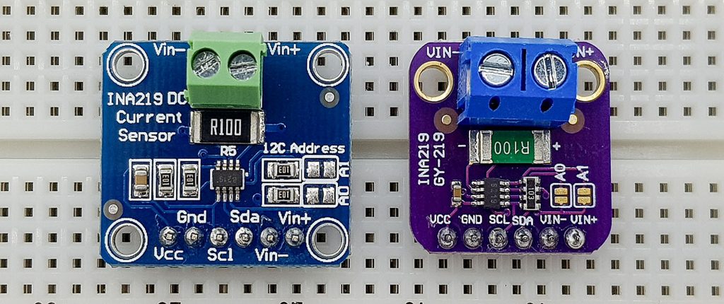
In this article I would like to introduce the INA219 current and power sensor module and my associated library INA219_WE.
In addition to the INA219, I tried out various other current sensor modules such as the ACS712 or the MAXIM471. However, I liked the INA219 best because it reliably detects currents of a few milliamperes. In addition to the current, the module also determines the power and voltage drop across the system to be measured. I will deal with the INA226, so to speak the brother of INA219, in another article.
Libraries for the INA219 already existed, but I wasn’t pleased with any. Either I lacked certain options such as the trigger mode or I found the functions a bit unwieldy to use. But the tastes are different. If you want to try alternative libraries, you can find some of them in the Arduino Library Manager at GitHub (under search term INA219).
Measuring principle of the INA219
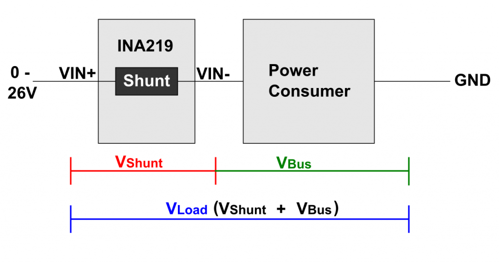
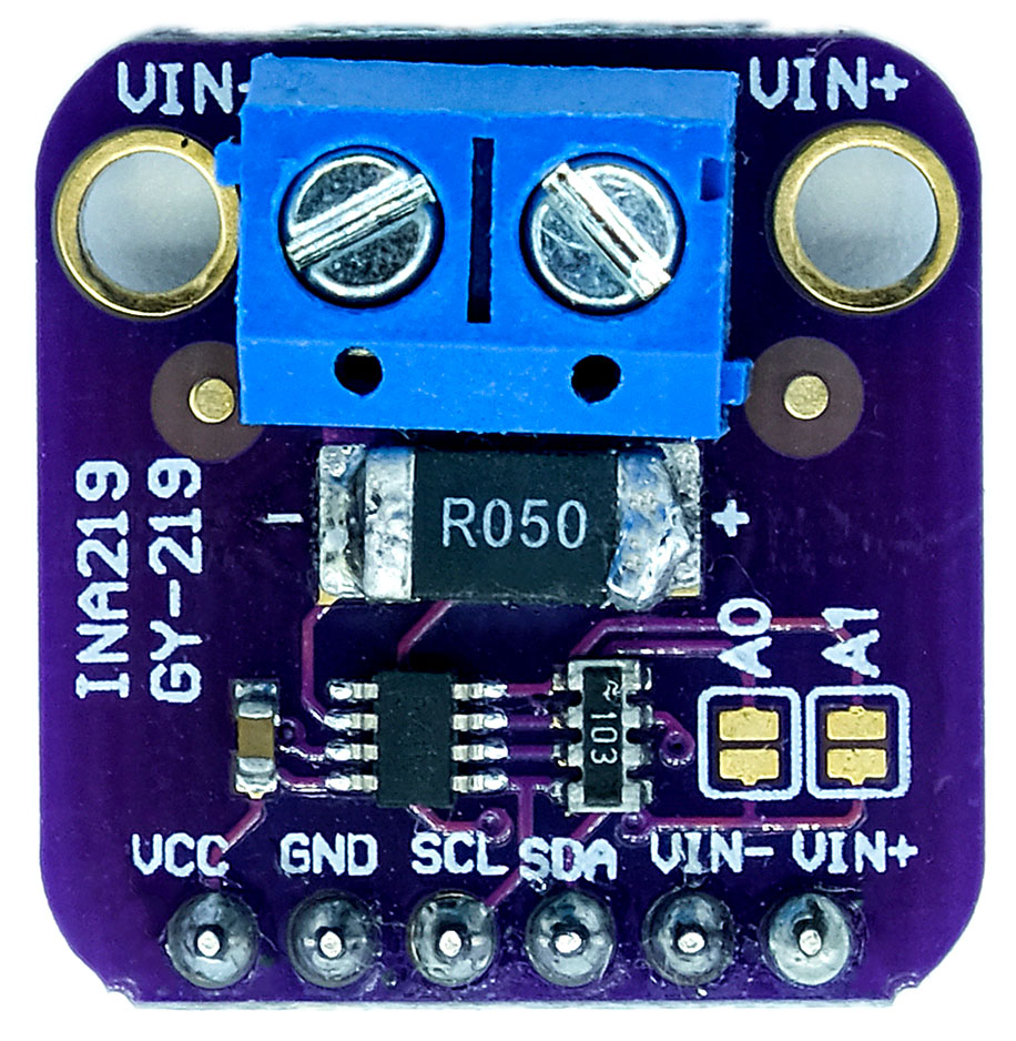
The measuring principle of the INA219 is simply based on Ohm’s law. The current to be measured is passed through a resistor and the voltage dropping across it is determined. Since one wants to interfere as little as possible with the system to be measured, the resistance is tiny. Such a current measuring resistor is called a shunt. In the case of the INA219 module, the shunt has a size of 0.1 Ohm (R100).
The INA219’s shunt is integrated into the consumer’s circuit as shown below. To calculate the size of the current, you basically just have to multiply the voltage drop across the shunt by 10. Why do you need something as complex as the INA219? Well, on the one hand, the voltage to be measured is small. So, you need an amplifier and – that’s anyway – an A/D converter. On the other hand, the INA219 can measure a little more than just the current.
In addition to the shunt voltage, the INA219 also determines the voltage drop across the consumer (“bus”) between VIN and GND. From this and from the size of the current, the INA219 calculates the power consumption of the consumer.
The circuit of shunt and consumer is separated from the supply current of the INA219. It is important, however, that the two have a common GND.
Typical circuit
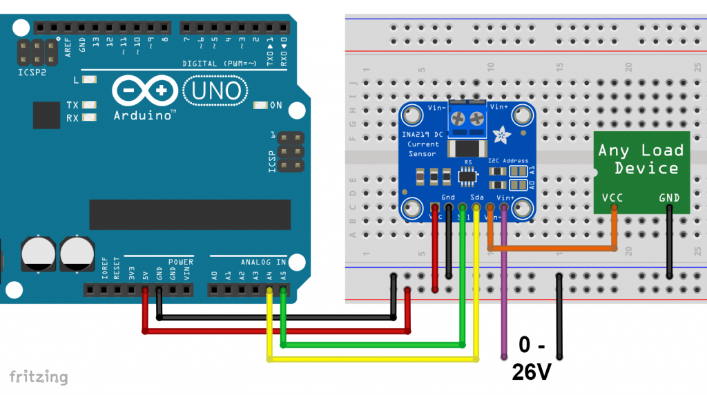
The INA219, more precisely the shunt, must be inserted into the circuit before the consumer, otherwise the measurement of the bus voltage will not work. This setup is called high-side.
The connection is simple. It doesn’t matter if you use the terminals or the pins for VIN+ and VIN-.
By the way, if you swap VIN- and VIN+ in the circuit shown above, you get negative values for the current and the shunt voltage.
Some technical data of the INA219 module
Here are the most important data of the INA219 module:
- Bus voltage: 0 – 26 volts
- maximum bus current: 3.2 amps (with 0.1 Ohm shunt)
- Supply voltage: 3 – 5.5 volts
- Power consumption (self-determined):
- Continuous mode: 0.7 mA
- Power-Down mode: 9.5 µA
- 4 gain levels (1-, 2-, 4-, 8-fold)
- Measurement modes: continuous or on-demand (“triggered”);
- Data registers:
- Shunt voltage register
- Bus voltage register
- Current register
- Power register
- Communication via I²C, 4 addresses can be set:
- 0x40: A0, A1 open
- 0x41: A0 closed, A1 open
- 0x44: A0 open, A1 closed
- 0x45: A0, A1 closed
- A further 12 addresses can be set (somewhat inconveniently) by connecting A0 or A1 with SDA or SCL (see data sheet).
If you want to check the I²C address, you can use my I²C scanner.
Further technical information can be found in the data sheet of the INA219.
You get the INA219 for a few euros in most online electronics stores, e.g. here at Amazon. More expensive are modules from Adafruit. I cannot judge whether the price difference is reflected in better quality.
Use of the INA219_WE library
You either install the library using the Arduino library manager, or you can download it from GitHub here.
Continuous mode
Build your circuit as shown above. Then upload the sample sketch “Continuous.ino”:
#include <Wire.h>
#include <INA219_WE.h>
#define I2C_ADDRESS 0x40

/* There are several ways to create your INA219 object:
 * INA219_WE ina219 = INA219_WE(); -> uses Wire / I2C Address = 0x40
 * INA219_WE ina219 = INA219_WE(I2C_ADDRESS); -> uses Wire / I2C_ADDRESS
 * INA219_WE ina219 = INA219_WE(&Wire); -> you can pass any TwoWire object
 * INA219_WE ina219 = INA219_WE(&Wire, I2C_ADDRESS); -> all together
 */
INA219_WE ina219 = INA219_WE(I2C_ADDRESS);

void setup() {
  Serial.begin(115200);
  Wire.begin();
  if(!ina219.init()){
    Serial.println("INA219 not connected!");
    while(1);
  }

  /* Set ADC Mode for Bus and ShuntVoltage
    * Mode *                 * Res / Samples *       * Conversion Time *
    INA219_BIT_MODE_9        9 Bit Resolution             84 µs
    INA219_BIT_MODE_10       10 Bit Resolution            148 µs
    INA219_BIT_MODE_11       11 Bit Resolution            276 µs
    INA219_BIT_MODE_12       12 Bit Resolution            532 µs  (DEFAULT)
    INA219_SAMPLE_MODE_2     Mean Value 2 samples         1.06 ms
    INA219_SAMPLE_MODE_4     Mean Value 4 samples         2.13 ms
    INA219_SAMPLE_MODE_8     Mean Value 8 samples         4.26 ms
    INA219_SAMPLE_MODE_16    Mean Value 16 samples        8.51 ms
    INA219_SAMPLE_MODE_32    Mean Value 32 samples        17.02 ms
    INA219_SAMPLE_MODE_64    Mean Value 64 samples        34.05 ms
    INA219_SAMPLE_MODE_128   Mean Value 128 samples       68.10 ms

    If you measure both current and bus voltage (which is the default), the conversion time doubles.
  */
  //ina219.setADCMode(INA219_SAMPLE_MODE_128); // choose mode and uncomment for change of default

  /* Set measure mode
    INA219_POWER_DOWN              - INA219 switched off
    INA219_TRIGGERED               - measurement on demand, current and bus
    INA219_TRIGGERED_CURRENT_ONLY  - on demand, current only
    INA219_TRIGGERED_BUS_ONLY      - on demand, bus voltage only
    INA219_ADC_OFF                 - analog/digital converter switched off
    INA219_CONTINUOUS              - continuous measurements (DEFAULT)
    INA219_CONTINUOUS_CURRENT_ONLY - continuous, current only
    INA219_CONTINUOUS_BUS_ONLY     - continuous, bus voltage only
  */
  // ina219.setMeasureMode(INA219_CONTINUOUS); // choose mode and uncomment for change of default

  /* Set PGain
     * Gain *     * Shunt Voltage Range *   * Max Current (if shunt is 0.1 ohms) *
    INA219_PG_40         40 mV                    0.4 A
    INA219_PG_80         80 mV                    0.8 A
    INA219_PG_160        160 mV                   1.6 A
    INA219_PG_320        320 mV                   3.2 A (DEFAULT)
  */
  // ina219.setPGain(INA219_PG_320); // choose gain and uncomment for change of default

  /* Set Bus Voltage Range
    INA219_BRNG_16   -> 16 V
    INA219_BRNG_32   -> 32 V (DEFAULT)
  */
  // ina219.setBusRange(INA219_BRNG_32); // choose range and uncomment for change of default

  Serial.println("INA219 Current Sensor Example Sketch - Continuous");

  /* If the current values delivered by the INA219 differ by a constant factor
    from values obtained with calibrated equipment you can define a correction factor.
    Correction factor = current delivered from calibrated equipment / current delivered by INA219
  */
  // ina219.setCorrectionFactor(0.98); // insert your correction factor if necessary

  /* If you experience a shunt voltage offset, that means you detect a shunt voltage which is not
    zero, although the current should be zero, you can apply a correction. For this, uncomment the
    following function and apply the offset you have detected.
  */
  // ina219.setShuntVoltOffset_mV(0.5); // insert the shunt voltage (millivolts) you detect at zero current

  /* If you use a shunt different from 0.1 ohms (R100), you can change the shunt size using the
    function below.
  */
  //ina219.setShuntSizeInOhms(0.01);
}

void loop() {
  float shuntVoltage_mV = 0.0;
  float loadVoltage_V = 0.0;
  float busVoltage_V = 0.0;
  float current_mA = 0.0;
  float power_mW = 0.0;
  bool ina219_overflow = false;

  shuntVoltage_mV = ina219.getShuntVoltage_mV();
  busVoltage_V = ina219.getBusVoltage_V();
  current_mA = ina219.getCurrent_mA();
  power_mW = ina219.getBusPower();
  loadVoltage_V  = busVoltage_V + (shuntVoltage_mV/1000);
  ina219_overflow = ina219.getOverflow();

  Serial.print("Shunt Voltage [mV]: "); Serial.println(shuntVoltage_mV);
  Serial.print("Bus Voltage [V]: "); Serial.println(busVoltage_V);
  Serial.print("Load Voltage [V]: "); Serial.println(loadVoltage_V);
  Serial.print("Current[mA]: "); Serial.println(current_mA);
  Serial.print("Bus Power [mW]: "); Serial.println(power_mW);
  if(!ina219_overflow){
    Serial.println("Values OK - no overflow");
  }
  else{
    Serial.println("Overflow! Choose higher shunt voltage range or a smaller shunt.");
  }
  Serial.println();

  delay(3000);
}
Parameter setting using the continuous.ino Sketch example
In this example, I would like to explain not only the continuous mode itself, but also the general setting parameters.
INA219_WE ina219 = INA219_WE() creates your INA219 object. I have implemented various options. You can pass a wire object and use the two I2C buses of an ESP32, for example.
The function init() ensures that the INA219 is activated with the default values. To change these basic settings, you can modify parameters in the setup:
- ADC mode for shunt and bus voltage conversion (
setADCMode()):- INA219_BIT_MODE_X: Single measurements with X bit resolution.
- INA219_SAMPLE_MODE_X: Average value from X measurements.
- Default setting: INA219_BIT_MODE_12.
- The times for the A/D conversion are specified in the sketch. Note that two conversions take place per measurement cycle, one for the shunt and one for the bus voltage.
- Measuring mode (
setMeasureMode())- INA219_CONTINUOUS – continuous: this is the default setting used here.
- INA219_TRIGGERED – “on request”: this is explained in the next example.
- You can also decide for CONTINUOUS and TRIGGERED whether you only want to determine the current or the bus voltage.
- INA219_ADC_OFF – Switch off the A/D converter.
- INA219_POWER_DOWN – switches the INA219 off. But better use the more comfortable
powerDown()function, which is explained below.
- Gain factor (
setPGain())- INA219_PG_X: The “X” indicates the limit for the shunt voltage. E.g.: PG_40 –> > 40 mV –> corresponds to a maximum current of 400 mA.
- INA219_PG_40: Gain = 1, INA219_PG_80: Gain = 1/2, INA219_PG_160: Gain = 1/4, INA219_PG_320: Gain = 1/8.
- Bus voltage range (
setBusRange())- 16 or 32 volts
You can also change the settings at any time later, i.e. outside the setup function.
With setCorrectionFactor(factor) you can introduce a correction factor if the current values determined with the INA219 should differ from those determined with calibrated measuring instruments. The factor is the quotient of the “correct” and the INA219 value. For me, all INA219 modules matched my multimeter well.
Apparently some INA219 modules show shunt voltage offsets. This means that although no current is flowing (load switched off), a shunt voltage is displayed and a resulting current. You can compensate for this with setShuntVoltOffset(). Enter the shunt voltage that you measure without current as a parameter in millivolts.
The function getOverflow() checks whether one of the data registers is overflowed. If this is the case, select a different gain factor.
The functions for reading the measurement results, such as getShuntVoltage_mV(), are self-explanatory.
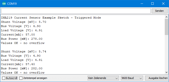
Output
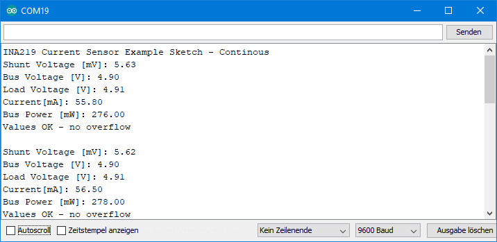
Attentive readers may ask why “Current” in this output example does not exactly match ten times the shunt voltage (RShunt was 0.1 Ohm). This is because the registers can be read at any time. The current conversion is not being waited for. The contents of the shunt and the current register can therefore originate from different measurement cycles. Another consequence is that the values can be up to 68.1 ms “old” (this would be the upper limit in SAMPLE_MODE_128). In continuous mode, however, this should not be a problem. In triggered mode, on the other hand, the system waits for the current conversion to complete after starting the measurement.
Triggered (“on request”) mode
The example sketch for triggered mode differs from the continuous sketch in only two lines. The mode is activated in line 49. In line 94, startSingleMeasurement() starts the measurement. Only when the measurement is completed, the output takes place.
#include <Wire.h>
#include <INA219_WE.h>
#define I2C_ADDRESS 0x40

/* There are several ways to create your INA219 object:
 * INA219_WE ina219 = INA219_WE(); -> uses Wire / I2C Address = 0x40
 * INA219_WE ina219 = INA219_WE(I2C_ADDRESS); -> uses Wire / I2C_ADDRESS
 * INA219_WE ina219 = INA219_WE(&Wire); -> you can pass any TwoWire object
 * INA219_WE ina219 = INA219_WE(&Wire, I2C_ADDRESS); -> all together
 */
INA219_WE ina219 = INA219_WE(I2C_ADDRESS);

void setup() {
  Serial.begin(115200);
  Wire.begin();
  if(!ina219.init()){
    Serial.println("INA219 not connected!");
    while(1);
}

  /* Set ADC Mode for Bus and ShuntVoltage
    * Mode *                 * Res / Samples *        * Conversion Time *
    INA219_BIT_MODE_9        9 Bit Resolution             84 µs
    INA219_BIT_MODE_10       10 Bit Resolution            148 µs
    INA219_BIT_MODE_11       11 Bit Resolution            276 µs
    INA219_BIT_MODE_12       12 Bit Resolution            532 µs  (DEFAULT)
    INA219_SAMPLE_MODE_2     Mean Value 2 samples         1.06 ms
    INA219_SAMPLE_MODE_4     Mean Value 4 samples         2.13 ms
    INA219_SAMPLE_MODE_8     Mean Value 8 samples         4.26 ms
    INA219_SAMPLE_MODE_16    Mean Value 16 samples        8.51 ms
    INA219_SAMPLE_MODE_32    Mean Value 32 samples        17.02 ms
    INA219_SAMPLE_MODE_64    Mean Value 64 samples        34.05 ms
    INA219_SAMPLE_MODE_128   Mean Value 128 samples       68.10 ms

    If you measure both current and bus voltage (which is the default), the conversion time doubles.
  */
  //ina219.setADCMode(INA219_SAMPLE_MODE_128); // choose mode and uncomment for change of default

  /* Set measure mode
    INA219_POWER_DOWN              - INA219 switched off
    INA219_TRIGGERED               - measurement on demand, current and bus
    INA219_TRIGGERED_CURRENT_ONLY  - on demand, current only
    INA219_TRIGGERED_BUS_ONLY      - on demand, bus voltage only
    INA219_ADC_OFF                 - analog/digital converter switched off
    INA219_CONTINUOUS              - continuous measurements (DEFAULT)
    INA219_CONTINUOUS_CURRENT_ONLY - continuous, current only
    INA219_CONTINUOUS_BUS_ONLY     - continuous, bus voltage only
  */
  ina219.setMeasureMode(INA219_TRIGGERED); // Triggered measurements for this example

  /* Set PGain
      * Gain *      * Shunt Voltage Range *   * Max Current (if shunt is 0.1 ohms) *
    INA219_PG_40          40 mV                   0.4 A
    INA219_PG_80          80 mV                   0.8 A
    INA219_PG_160         160 mV                  1.6 A
    INA219_PG_320         320 mV                  3.2 A (DEFAULT)
  */
  // ina219.setPGain(INA219_PG_320); // choose gain and uncomment for change of default

  /* Set Bus Voltage Range
    INA219_BRNG_16   -> 16 V
    INA219_BRNG_32   -> 32 V (DEFAULT)
  */
  // ina219.setBusRange(INA219_BRNG_32); // choose range and uncomment for change of default

  /* If the current values delivered by the INA219 differ by a constant factor
    from values obtained with calibrated equipment you can define a correction factor.
    Correction factor = current delivered from calibrated equipment / current delivered by INA219
  */
  // ina219.setCorrectionFactor(0.98); // insert your correction factor if necessary

  /* If you experience a shunt voltage offset, that means you detect a shunt voltage which is not
    zero, although the current should be zero, you can apply a correction. For this, uncomment the
    following function and apply the offset you have detected.
  */
  // ina219.setShuntVoltOffset_mV(0.0); // insert the shunt voltage (millivolts) you detect at zero current

  /* If you use a shunt different from 0.1 ohms (R100), you can change the shunt size using the
    function below.
  */
  //ina219.setShuntSizeInOhms(0.01);

  Serial.println("INA219 Current Sensor Example Sketch - Triggered Mode");
}

void loop() {
  float shuntVoltage_mV = 0.0;
  float loadVoltage_V = 0.0;
  float busVoltage_V = 0.0;
  float current_mA = 0.0;
  float power_mW = 0.0;
  bool ina219_overflow = false;

  ina219.startSingleMeasurement(); // triggers single-shot measurement and waits until completed
  shuntVoltage_mV = ina219.getShuntVoltage_mV();
  busVoltage_V = ina219.getBusVoltage_V();
  current_mA = ina219.getCurrent_mA();
  power_mW = ina219.getBusPower();
  loadVoltage_V  = busVoltage_V + (shuntVoltage_mV/1000);
  ina219_overflow = ina219.getOverflow();

  Serial.print("Shunt Voltage [mV]: "); Serial.println(shuntVoltage_mV);
  Serial.print("Bus Voltage [V]: "); Serial.println(busVoltage_V);
  Serial.print("Load Voltage [V]: "); Serial.println(loadVoltage_V);
  Serial.print("Current[mA]: "); Serial.println(current_mA);
  Serial.print("Bus Power [mW]: "); Serial.println(power_mW);
  if(!ina219_overflow){
    Serial.println("Values OK - no overflow");
  }
  else{
    Serial.println("Overflow! Choose higher shunt voltage range or a smaller shunt.");
  }
  Serial.println();

  delay(3000);
}
In triggered mode, all output values belong to one measurement cycle:
Triggered -non-blocking
The Triggered.ino sketch waits after startSingleMeasurement() until a measurement value is available and thus blocks the sketch. This may not be desired. I have implemented startSingleMeasurementNoWait() for this purpose. You can use getConversionReady() to check whether a measured value is available. The following sketch illustrates how this works:
#include <Wire.h>
#include <INA219_WE.h>
#define I2C_ADDRESS 0x40

/* There are several ways to create your INA219 object:
 * INA219_WE ina219 = INA219_WE(); -> uses Wire / I2C Address = 0x40
 * INA219_WE ina219 = INA219_WE(I2C_ADDRESS); -> uses Wire / I2C_ADDRESS
 * INA219_WE ina219 = INA219_WE(&Wire); -> you can pass any TwoWire object
 * INA219_WE ina219 = INA219_WE(&Wire, I2C_ADDRESS); -> all together
 */
INA219_WE ina219 = INA219_WE(I2C_ADDRESS);

void setup() {
  Serial.begin(115200);
  Wire.begin();
  if(!ina219.init()){
    Serial.println("INA219 not connected!");
    while(1);
}

  /* Set ADC Mode for Bus and ShuntVoltage
    * Mode *                 * Res / Samples *        * Conversion Time *
    INA219_BIT_MODE_9        9 Bit Resolution             84 µs
    INA219_BIT_MODE_10       10 Bit Resolution            148 µs
    INA219_BIT_MODE_11       11 Bit Resolution            276 µs
    INA219_BIT_MODE_12       12 Bit Resolution            532 µs  (DEFAULT)
    INA219_SAMPLE_MODE_2     Mean Value 2 samples         1.06 ms
    INA219_SAMPLE_MODE_4     Mean Value 4 samples         2.13 ms
    INA219_SAMPLE_MODE_8     Mean Value 8 samples         4.26 ms
    INA219_SAMPLE_MODE_16    Mean Value 16 samples        8.51 ms
    INA219_SAMPLE_MODE_32    Mean Value 32 samples        17.02 ms
    INA219_SAMPLE_MODE_64    Mean Value 64 samples        34.05 ms
    INA219_SAMPLE_MODE_128   Mean Value 128 samples       68.10 ms

    If you measure both current and bus voltage (which is the default), the conversion time doubles.
  */
  ina219.setADCMode(INA219_SAMPLE_MODE_128);

  /* Set measure mode
    INA219_POWER_DOWN              - INA219 switched off
    INA219_TRIGGERED               - measurement on demand, current and bus
    INA219_TRIGGERED_CURRENT_ONLY  - on demand, current only
    INA219_TRIGGERED_BUS_ONLY      - on demand, bus voltage only
    INA219_ADC_OFF                 - analog/digital converter switched off
    INA219_CONTINUOUS              - continuous measurements (DEFAULT)
    INA219_CONTINUOUS_CURRENT_ONLY - continuous, current only
    INA219_CONTINUOUS_BUS_ONLY     - continuous, bus voltage only
  */
  ina219.setMeasureMode(INA219_TRIGGERED); // Triggered measurements for this example

  /* Set PGain
     * Gain *      * Shunt Voltage Range *   * Max Current (if shunt is 0.1 ohms) *
    INA219_PG_40          40 mV                   0.4 A
    INA219_PG_80          80 mV                   0.8 A
    INA219_PG_160         160 mV                  1.6 A
    INA219_PG_320         320 mV                  3.2 A (DEFAULT)
  */
  // ina219.setPGain(INA219_PG_320); // choose gain and uncomment for change of default

  /* Set Bus Voltage Range
    INA219_BRNG_16   -> 16 V
    INA219_BRNG_32   -> 32 V (DEFAULT)
  */
  // ina219.setBusRange(INA219_BRNG_32); // choose range and uncomment for change of default

  /* If the current values delivered by the INA219 differ by a constant factor
    from values obtained with calibrated equipment you can define a correction factor.
    Correction factor = current delivered from calibrated equipment / current delivered by INA219
  */
  // ina219.setCorrectionFactor(0.98); // insert your correction factor if necessary

  /* If you experience a shunt voltage offset, that means you detect a shunt voltage which is not
    zero, although the current should be zero, you can apply a correction. For this, uncomment the
    following function and apply the offset you have detected.
  */
  // ina219.setShuntVoltOffset_mV(0.0); // insert the shunt voltage (millivolts) you detect at zero current

  /* If you use a shunt different from 0.1 ohms (R100), you can change the shunt size using the
    function below.
  */
  //ina219.setShuntSizeInOhms(0.01);

  Serial.println("INA219 Current Sensor Example Sketch - Triggered Mode, non-blocking");
  ina219.startSingleMeasurementNoWait(); // triggers single-shot measurement without waiting
}

void loop() {
  static unsigned int counter = 0;
  if(ina219.getConversionReady()){
    counter++;
    if(counter == 9) {  // display only every 10th conversion, just to slow down the output
      displayResults(); // with the current settings, the output period is ~1.28 s
      counter = 0;
    }
    ina219.startSingleMeasurementNoWait();
  }
}

void displayResults() {
  float shuntVoltage_mV = 0.0;
  float loadVoltage_V = 0.0;
  float busVoltage_V = 0.0;
  float current_mA = 0.0;
  float power_mW = 0.0;
  bool ina219_overflow = false;

  shuntVoltage_mV = ina219.getShuntVoltage_mV();
  busVoltage_V = ina219.getBusVoltage_V();
  current_mA = ina219.getCurrent_mA();
  power_mW = ina219.getBusPower();
  loadVoltage_V  = busVoltage_V + (shuntVoltage_mV/1000);
  ina219_overflow = ina219.getOverflow();

  Serial.print("Shunt Voltage [mV]: "); Serial.println(shuntVoltage_mV);
  Serial.print("Bus Voltage [V]: "); Serial.println(busVoltage_V);
  Serial.print("Load Voltage [V]: "); Serial.println(loadVoltage_V);
  Serial.print("Current[mA]: "); Serial.println(current_mA);
  Serial.print("Bus Power [mW]: "); Serial.println(power_mW);
  if(!ina219_overflow){
    Serial.println("Values OK - no overflow");
  }
  else{
    Serial.println("Overflow! Choose higher shunt voltage range or a smaller shunt.");
  }
  Serial.println();
}
Power-Down Mode
With the Power-Down mode, you can reduce the current consumption of the INA219 from approx. 0.7 mA to less than 10 µA (own measurements). 0.7 mA is already a fairly small value, but that’s still more than 6000 mAh per year. This is relevant for battery-powered projects.
The following example sketch shows the power-down mode in action. The sketch initializes the INA219 with the default parameters. Five sets of measurements are output every three seconds. The function powerDown() then backs up the content of the configuration register and switches off the INA219. The function powerUp() writes back the copy of the configuration register. On the one hand, this write operation wakes up the INA219, and on the other hand, it ensures that the INA219 returns to the previously selected mode (here: continuous).
#include <Wire.h>
#include <INA219_WE.h>
#define I2C_ADDRESS 0x40

/* There are several ways to create your INA219 object:
 * INA219_WE ina219 = INA219_WE(); -> uses Wire / I2C Address = 0x40
 * INA219_WE ina219 = INA219_WE(I2C_ADDRESS); -> uses Wire / I2C_ADDRESS
 * INA219_WE ina219 = INA219_WE(&Wire); -> you can pass any TwoWire object
 * INA219_WE ina219 = INA219_WE(&Wire, I2C_ADDRESS); -> all together
 */
INA219_WE ina219 = INA219_WE(I2C_ADDRESS);

void setup() {
  Serial.begin(115200);
  Wire.begin();
  // default parameters are set - for change check the other examples
  if(!ina219.init()){
    Serial.println("INA219 not connected!");
    while(1);
  }
  Serial.println("INA219 Current Sensor Example Sketch - PowerDown");
  Serial.println("Continuous Sampling starts");
  Serial.println();
}

void loop() {
  for(int i=0; i<5; i++){
    continuousSampling();
    delay(3000);
  }

  Serial.println("Power down for 10s");
  ina219.powerDown();
  for(int i=0; i<10; i++){
    Serial.print(".");
    delay(1000);
  }

  Serial.println("Power up!");
  Serial.println("");
  ina219.powerUp(); // requires 40 µs
}

void continuousSampling(){
  float shuntVoltage_mV = 0.0;
  float loadVoltage_V = 0.0;
  float busVoltage_V = 0.0;
  float current_mA = 0.0;
  float power_mW = 0.0;
  bool ina219_overflow = false;

  shuntVoltage_mV = ina219.getShuntVoltage_mV();
  busVoltage_V = ina219.getBusVoltage_V();
  current_mA = ina219.getCurrent_mA();
  power_mW = ina219.getBusPower();
  loadVoltage_V  = busVoltage_V + (shuntVoltage_mV/1000);
  ina219_overflow = ina219.getOverflow();

  Serial.print("Shunt Voltage [mV]: "); Serial.println(shuntVoltage_mV);
  Serial.print("Bus Voltage [V]: "); Serial.println(busVoltage_V);
  Serial.print("Load Voltage [V]: "); Serial.println(loadVoltage_V);
  Serial.print("Current[mA]: "); Serial.println(current_mA);
  Serial.print("Bus Power [mW]: "); Serial.println(power_mW);
  if(!ina219_overflow){
    Serial.println("Values OK - no overflow");
  }
  else{
    Serial.println("Overflow! Choose higher shunt voltage range or a smaller shunt.");
  }
  Serial.println();
}
Changing the shunt
Despite an intensive search, I have only found modules with a 0.1 ohm shunt. This limits you to a current of 3.2 amperes. If you want to measure larger currents, you have three options:
- Do not use a module, but the bare INA219 chip.
- You desolder the R100 shunt and replace it. However, this is not trivial with just one soldering iron.
- Pragmatic solution: simply solder a second shunt onto the first shunt (sandwich-like).
I have tried way 3 (see right). Two parallel shunts of 0.1 and 0.05 ohm result in a total shunt of 0.0333 ohm. It worked wonderfully.
Use setShuntSizeInOhms() to define the shunt. setPGain() also works with the changed shunt. When using PG_Value and a shunt with resistance R, the maximum current is I:
![\[ I_{\text{max}}\;\text{[A]}= \frac{Value}{R\cdot 1000} \]](https://wolles-elektronikkiste.de/wp-content/ql-cache/quicklatex.com-9fd76a6876fbe280164327470311daf8_l3.png "Rendered by QuickLaTeX.com")
Overview of all functions of the library
And here is an overview of all the functions. It is part of my documentation on GitHub.
Details of the library and the registers
This part is only for those who want to go into the details of the INA219_WE library or to better understand the internal processes in INA219.
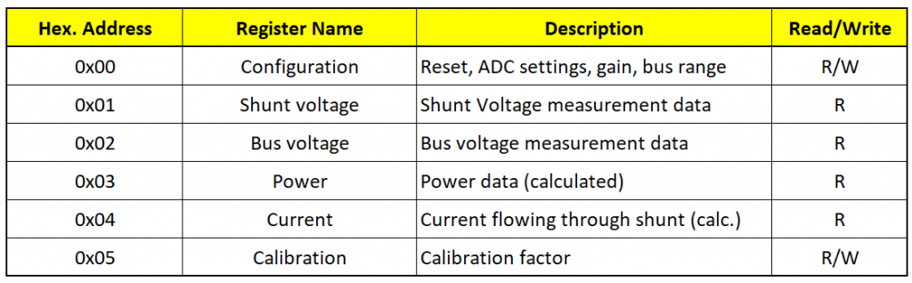
The registers of INA219
The INA219 has six 16-bit registers. You can only write to the configuration and calibration registers. The other registers provide the measured or calculated data and are read-only accordingly.
The basic settings are made in the configuration register:
The configuration register

- RST: Setting the RST bit triggers a reset. The register contents are reset to default.
- BRNG: Bus Range determines the range of the bus voltage, i.e. 16 or 32 volts.
- PGX: The two bits determine PGAIN
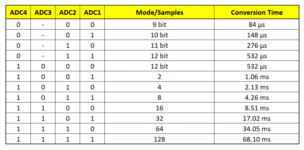
- BADCX / SADCX: These bits determine the resolution or the number of measurements per measurement cycle for the bus and shunt voltage (see table). In my library, no different values can be written in BADC and SADC. I had decided not to make the operation too complex.
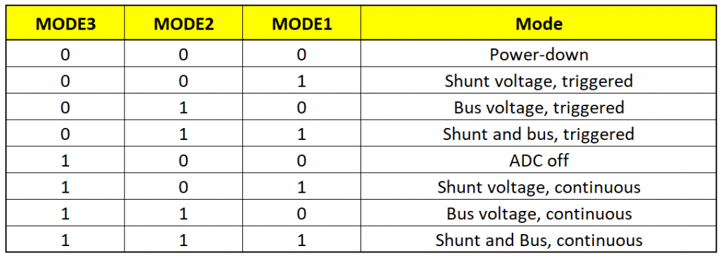
- MODEX: The three mode bits set the operating mode (see table). Again, I haven’t implemented everything that’s possible. Only the modes highlighted in green are available.
The other registers
The shunt and the current register are not particularly exciting. It should be noted, however, that both have sign bits, i.e. they can take values between +32767 and -32767. The Bus Voltage and the Power Register are not signed.
Regarding the Bus Voltage Register, only 13 bits are available for the bus voltage (BD0 – BD12). Bit No. 2 is unused, bit No. 1 is CNVR (Conversion Ready). It is set when (fresh) data are available in the registers, i.e. all measurements and calculations for a cycle are complete. Reading the Power Register deletes the bit. Bit 0 is OVF (overflow) and indicates whether one of the data registers has overflowed. To calculate the bus voltage, the content of the bus voltage register must be shifted 3 bits to the right.

The Calibration Register contains the 15 bit calibration factor “Cal”. The register is 16 bits, but bit 0 is reserved. We’ll get to what the calibration factor is all about. But, to avoid misunderstandings, I should point out that the calibration factor has nothing to do with the correction factor ( setCorrectionFactor() ).
INA219 – internal calculations
I found the explanations of the calculations in the data sheet very confusing. I had to read it several times before I understood it. But actually it’s not that bad.
To determine the calibration factor, first consider the maximum expected current (maxExpectedCurrent). This must fit in the Current Register. Since the Current Register has a value range of +/- 215, the Current_LSB (ampere per bit) therefore is:
![\[ Current\_LSB = \frac{maxExpectedCurrent}{2^{15}} \]](https://wolles-elektronikkiste.de/wp-content/ql-cache/quicklatex.com-f7dd5e8967cf5d12f16e22ee0da697dc_l3.png "Rendered by QuickLaTeX.com")
The equation usually results in a “crooked” value. You round it up so that in the next step you get a straight value for the calibration factor Cal. You calculate Cal according to the following formula:
![\[ Cal = trunc\left(\frac{0,\!04096}{Current\_LSB\cdot R_{Shunt}}\right) \]](https://wolles-elektronikkiste.de/wp-content/ql-cache/quicklatex.com-d096a8f564b1cf28662e31da199e7c16_l3.png "Rendered by QuickLaTeX.com")
0.04096 is an internally defined value, which ensures a reasonable scaling, i.e. that the values make good use of the register width.
The Shunt Voltage Register contains the shunt voltage in 10 µV / bit. Since it is a signed register, the maximum is 215-1. This results in a maximum shunt voltage of 0.32767 volts. More does not fit in the register. As the shunt resistance is 0.1 ohm, this theoretically results in a maximum current of approx. 3.2 amperes.
The Current Register is calculated according to the following formula (but we don’t have to worry about that):
![\[ currentRegister=\frac{shuntVoltageRegister \cdot Cal}{4096} \]](https://wolles-elektronikkiste.de/wp-content/ql-cache/quicklatex.com-c5aac7bd6f8f449b014308b441a9ea6c_l3.png "Rendered by QuickLaTeX.com")
Power_LSB, i.e. the power per bit (watt/bit), is 20 times the Current_LSB. This is a fixed internal setting.
![\[ Power\_LSB = 20 \cdot Current\_LSB \]](https://wolles-elektronikkiste.de/wp-content/ql-cache/quicklatex.com-00ff86118bef1b864e8222fec3435579_l3.png "Rendered by QuickLaTeX.com")
The content of the Power Register can be calculated from the content of the Current Register and the Bus Voltage Register. But we don’t have to worry about that either because the INA219 calculates that internally.
![\[ powerRegister = \frac{currentRegister \cdot busVoltageRegister}{5000} \]](https://wolles-elektronikkiste.de/wp-content/ql-cache/quicklatex.com-75f09e58c052b112065406f7c6d9b6a6_l3.png "Rendered by QuickLaTeX.com")
The Bus Voltage Register has a fixed LSB of 4 mV/bit.
Calculations by the library
Basically, you could just read the Shunt and Bus Voltage Register and calculate the rest. But we let the INA219 work for us.
Nevertheless, the values read from the registers still need to be converted:
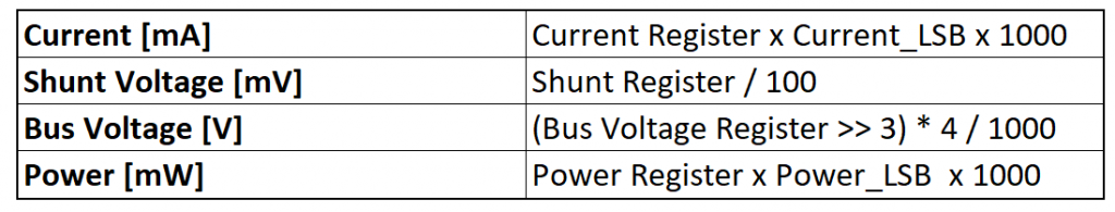
To get more convenient values, I introduced a Current Divider and a Power Multiplier:
![\[ current\ \text{[mA]}=\frac{currentRegister}{currentDivider} \]](https://wolles-elektronikkiste.de/wp-content/ql-cache/quicklatex.com-6bd89d8474456d8a93e94f0b7004ed29_l3.png "Rendered by QuickLaTeX.com")
![\[ \text{mit / with}\ \ \ currentDivider = \frac{1}{Current\_LSB \cdot 1000} \]](https://wolles-elektronikkiste.de/wp-content/ql-cache/quicklatex.com-a2c96ed7725803a2d2b485001469d6d2_l3.png "Rendered by QuickLaTeX.com")
and
![\[ power\ \text{[mW]} = powerRegister\cdot powerM\!ultiplier \]](https://wolles-elektronikkiste.de/wp-content/ql-cache/quicklatex.com-ae4166ab8c6aebfdcd78489f3b70e779_l3.png "Rendered by QuickLaTeX.com")
![\[ \text{mit / with}\ \ \ powerM\!ultiplier = Power\_LSB \cdot 1000 \]](https://wolles-elektronikkiste.de/wp-content/ql-cache/quicklatex.com-bb77a40f99953cca8571168c3915b75b_l3.png "Rendered by QuickLaTeX.com")
Measuring ranges implemented in the library
The maximum resolution for the current results from the LSB of the shunt voltage register (10 µV) and the shunt size (0.1 Ω). Imin = Umin/R = 100 µA = 0.1 mA. In the following table, I have calculated the measurement ranges implemented in the library and the resulting LSBs for current and power.
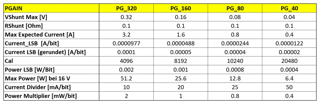
The calculated Current LSBs are smaller than the actual possible resolution, except for PG_320. So don’t be misled by the values. You would only achieve advantages in resolution with larger shunts.
Acknowledgement
I took the INA219 Fritzing component from the Adafruit Fritzing Part collection on GitHub.
The post image is from the Free-Photos on Pixabay and was slightly modified by me.
Dear Wolfang, thank you so much for your precious work and for sharing it. Do you have experience with your library to measure an AC load ?(suitably scaled by a current transformer). What operating mode do you recommend? I think it is needed to sample according to Shannon’s theorem and then calculate the RMS value. Thanks in advance.
Hi Luca, I would not say that it is impossible to measure AC currents with the INA219, but at least it is maybe not the ideal tool for that purpose. But if you want to try, I would appreciate it if you could share your experience. I have no own experience. What you will measure with the INA219 is alternating currents from positive to negative. How good this will work – I don’t know. I had to look up what Shannon’s theorem is – interesting, I have learned something today! And as far as I have understood it, it is theoretically possible to derive the current from the data. The conversion time should be as short as possible, and you should not choose a mode that is averaging results. I would start with the 12 Bit conversion, which takes roughly 0.5 ms. The single shot mode might be better than the continuous mode. The I2C frequency should be set to 400 kHz. You should not print all measured values on the serial monitor because this is very slow. Good luck!
hi Wolfgang, theoretically it should be possible. A sampling rate of 100 samples per second should allow to reconstruct a sine wave with a frequency of 50 hertz. Sampling at least every 10 ms and calculating the RMS value over some period should return reliable values. I will continue with the tests. Eventually I will let you know. thank you very much and many compliments!!
After some test and some tuning I can confirm that in a triggered mode, with an appropriate sampling rate, the library do a good job on AC loads also. It returns no so bad accurately current measurement.
Thanks you. Good bye
Hi, great that it works! I was not very optimistic. I learned something 😀.
Can you suggest change needed to work with ESP32?
You don’t need to change the sketches. They work as they are. On the hardware side, you need to choose the correct I2C Pins (usually 21/22). And you should run the INA219 board with 3.3 volts; otherwise you might need voltage dividers for the I2C connection because the ESP32 I2C pins don’t like 5 volts.
Hi Wolfgang,
I’m wondering if there is not an error in your last table “Measuring ranges, resolution and conversion factors”.
The current_LSB(A/bit) seems right for the PGA_320 as the result of the register is on 15 bits (3.2/32767).
But, for the other PGA, PGA_160 (14 bits), PGA_80 (13 bits) and PGA_40 (12 bits), as the register return is lower than 15 bits, it cannot be divided again by 32767 but by the number of bits returned.
Which means that whatever the PGA, the current_LSB will be always 100uA in your case.
Or I missed something…
Hi Laurent,
you are right. With an 0.1 ohms shunt, the resolution is limited to 100 µA since the LSB of the voltage register is 10 µV and the shunt register is the basis for all other calculations. It’s already quite some time on my (long) to-do-list to rewrite this. The problem is, I took some of the calculations over from the Adafruit library: https://github.com/adafruit/Adafruit_INA219/blob/master/Adafruit_INA219.cpp and was blinded by the low current LSBs, which are not achievable.
Thanks for the comment!
Regards, Wolfgang
Compilation error: INA219_WE.h: No such file or directory
Manage to install the library from zip, but now this one for Continuous_ATTINY:
C:\Users\xps\AppData\Local\Arduino15\packages\arduino\hardware\avr\1.8.6\libraries\Wire\src\utility\twi.c:530:46: error: ‘TWEN’ undeclared (first use in this function); did you mean ‘TWINT’?
TWCR = _BV(TWINT) | _BV(TWSTA)| _BV(TWEN) ;
My mistake, forgot to uncomment
/* Uncomment the following line to use TinyWireM instead of Wire */
#define USE_TINY_WIRE_M_
Thanks for letting me know! I hope all works fine now.
Thank you, work flawlessly.
I need to use both an INA226 and an INA219 in a project and would like to use both of your libraries INA229_WE and INA219_WE. But when I use both #include and #include my sketch gives errors like ‘POWER_DOWN’ conflicts with a previous declaration. Similarly for TRIGGERED. and CONTINUOUS.
What can I do to resolve this problem?
type in my comment – INA229_WE should have been INA226_WE.
Hi,
when I developed the library I did not choose the best enum names for the measure modes. E.g. “POWER_DOWN” is used in INA226_WE as well as in INA219_WE. Basically it is easy to fix for me by choosing different names, but it would mean that a new version would not be backward compatible. So, I have chosen a different way. I have added a file “INA226_WE_config.h”. You find it in your library folder under INA226_WE/src. Open this file and uncomment the line: #define INA226_WE_COMPATIBILITY_MODE_. Then you use INA226_CONTINUOUS instead of CONTINUOUS, INA226_POWER_DOWN instead of POWER_DOWN and INA226_TRIGGERED instead of TRIGGERED. I have kept INA219_WE unchanged in this respect.
I have implemented this change in version 1.2.8. Usually, it takes some hours until you are notified by the Arduino IDE that the update is available. If you don’t want to wait, you can install the new version from GitHub manually.
In case I will launch further updates in the future, you will have to apply the change in INA226_WE_config.h again.
Thanks for the quick response, Wolfgang! I’ll give it a try tomorrow.
Welcome! This module can be used in a circuit with a consumption of 300V 0-100mA for current measurement, or what do you recommend in this range if it is not suitable? Thanks: Diszk
100 milliamps is no problem but 300 volt is too much. The bus voltage is limited to 26 volts.
Thank you very much for your answer! I want to measure the anode current of an electron tube. Could you suggest a module for the drawing below? https://ibb.co/DQ3DvM1 Thanks!
The ACS712 would be suitable for the 300 V but not so much for the 100 mA. The sensitivity is not very high in that low range. You could use an INA226:
https://wolles-elektronikkiste.de/en/ina226-current-and-power-sensor
This module has a separate input for the bus voltage. So, you can connect the input/output on the low voltage side and use a voltage divider on the high voltage side to get the highest expected bus voltage to lower than 36 V which is the maximum. The current values would be correct, the bus voltage and power values would have to be multiplied by the voltage divider value.
Best regards, Wolfgang
Thanks for the help! Sorry for so many beginner questions. According to the attached photo, will it be good? https://ibb.co/BNdr0dM
Üdvözlettel, János
The VBUS connection is correct. But IN+/IN- have to be connected on the low voltage side
which means between Load and GND.
300 volts can be quite dangerous, so you should be very sure what you are doing. You might consider to let an expert check your circuit (not only on “paper”). My advices are given by best knowledge, but I can’t accept any liability.
Thanks! It really helped me understand the basics! Good health to You! Best regards, János from Hungary
Like others here I truly appreciate all the hard work you put into this web page and the code. Like another user, I’m using a https://wiki.dfrobot.com/Gravity%3A%20I2C%20Digital%20Wattmeter%20SKU%3A%20SEN0291.
Using the SetShuntSize code I have adjusted this line:
ina219.setShuntSizeInOhms(0.01);
The Bus Voltage and Load Voltage appear to be correct at ~25vdc.
The other readings appear to be off.
16:07:05.576 -> Shunt Voltage [mV]: -0.43
16:07:05.576 -> Bus Voltage [V]: 25.06
16:07:05.610 -> Load Voltage [V]: 25.06
16:07:05.643 -> Current[mA]: -43.00
16:07:05.676 -> Bus Power [mW]: -1077.41
16:07:05.676 -> Values OK – no overflow
I am using a simple boost converter to generate 24 VDC from the Arduino 5 VDC:
https://www.amazon.com/dp/B0C54TDQXC?psc=1&ref=ppx_yo2ov_dt_b_product_details
I am using a generic 4-20mA pressure sensor as the load:
https://www.amazon.com/dp/B08BLJZ9YR?psc=1&ref=ppx_yo2ov_dt_b_product_details
Any suggestions on how to debug? I think I have all of the grounds “connected”.
THANKS!
If the shunt voltage is negative, you just need to change IN- and IN+.
Why the values are outside the 4 – 20 mA that one would expect is something I don’t know. If you have a multimeter you can check the real value. I have no experience with the DFRobot module but I would expect it works reliably. If you don’t have a multimeter, just take a 5 V power supply and a 1 kohm resistor and test if you measure 5 mA. If yes, then the DFRobot module is OK.
Based on the assumption that the shunt voltage is correct, the current is also correct (0.43 mV/ 0.01 ohms). Same for the bus power (0.43 mA * 25.06 volts). If you suspect it is related with my library you can try the DFRobot Lib.
A step-up converter is not the most stable power supply. Because of its working principle there is a ripple signal on the output voltage:
https://wolles-elektronikkiste.de/en/voltage-regulation-linear-and-switching-regulators#Anker_7
But I don’t think this is the problem here.
So, not a perfect answer, but at least there are things you can try in order to identify if the issue is related with the lib, the DFRobot module or the pressure sensor.
Thanks Wolfgang . In the end I think it might just be the DFRobot product. The shunt resistor is marked R010 but it measures .8 ohms. Wish I had thought of that a few hours ago. Using a generic INA219 your code is working perfectly. Thanks again for your incredible work and assistance to the community.
Hello, i have a question about the accuracy of INA219, i want to measure low current between 2mA and 20mA, with bus voltage of 15V, im using your library with default setting but i m getting an accurancy of 15%to 20%, is there any way to get better accurancy as TI annouce that the INA219 is 1%, i even tried to change the settings as PGA but no improvement, i have several INA with different addresses connected to an ESP32.
Thnak you so much.
Hi, have you tried to change the measuring mode, e.g.:
ina219.setADCMode(SAMPLE_MODE_128); ?
the default is a single measurement. Maybe you play a bit with the parameters. A stable power supply for the INA219 can also potentially help. You could add a capacitor.
Hi Wolfgang, it is quite a long time from my last posting here. Hope your doing well after the last terrible period.
Following your indications, and using your sketch, I was finally able to make the INA working as expected.
Now I decided to include this module in a new project (a MCU controlled PSU) with the same sketch, but I get something really unexpected: totally wrong V and A readings.
Actually I get a fixed result: V=-20447 , I=16546, with and withot any load
I tried with 2 differents sensors, with a minimal difference in readings.
The INA address is 0x40, verified with the I2Cscanner and in the project there is also a I2C OLED display working perfectly, so it should not be a communication problem, I believe.
Maybe I’m doing something wrong in my project; the question is: can I connect the Vin+ pin to the module VCC (i.e. +5V) and apply the load between the Vin- and GND pins?
It should be simple, right? Or the module wants to have the Vin+ pin supplied by a different source?
Otherwise I do not have any other idea.
Many thanks for any usefull info and continue with your fantastic work.
Ciao from Italy.
P.S. I receive your posting but unfortunately they are in German and I have some difficulties in reading them 🙂
Hi Giacomo, the answer to “can I connect the Vin+ pin to the module VCC (i.e. +5V) and apply the load between the Vin- and GND pins?” is yes, as long as the power supply is stable. But even if not, that would not explain your strange results. Do you have all GNDs connected? That is important and could explain strange results. If this is not the issue, can you send me photos of your circuit? To: wolfgang.ewald@wolles-elektronikkiste.de. Maybe I see something. Ciao from Germany!
Hi Wolfang, I don’t how to say it…it was just a gigantic failure in the SW, and in my mind too…what a shame. I tested the new SW with my old, functioning project, and I got the same wrong results.
Looking again at the SW, with my eyes well open, I find an incredible error, which I’m too ashamed to report. Correct it, everything is now working again,
I’m really sorry to have bothered you.
Thanks again for your very quick answer
Giacomo
Don’t worry. I am just happy to hear that it works!
Hello Wolfgang,
this so far the best in219 library i have tryed ,very good one ,i have question about SAMPLE_MODE_X,is resolution of every sample taken 12 Bit?
Hi, yes, if you choose SAMPLE_MODE_X, the resolution will be 12 Bit. Only if you choose any of the BIT_MODE_X options the resolution is <= 12 Bit. I should maybe mention it explicitely.
Hi Wolfgang
Great library. Just thought I’d mention a typo. In the table of functions on the English page you show the power function as getBusPower_mW(), when in fact it is just getBusPower().
Thanks again.
Hi Ian, thanks. I will correct it. I am happy about every issue that is reported!
Thanks Wolfgang for your very detailed and clear article, the best I ever found in the Arduini (and related) world.
This is my very first attempt in using an INA219, quite a nice object, on a board bought on Amazazon from some chinese firm; the picture is anyway the most common found on Internet.
I use your sketch and it is working very well, I presume…since there a couple of things in the value that are wrong for sure:
1. without any load or power source I get a costant Bus Voltage of 1.06V
2. connecting a 9V battery and a load of 1K resistor I get these results:
Shunt Voltage [mV]: 0.00
Bus Voltage [V]: 8.34
Load Voltage [V]: 0.00
Current[mA]: 8.80
Bus Power [mW]: 0.00
Values OK – no overflow
So, there is not any Load Voltage and the Bus Power is 0.
I do suspect that my board is failing, unfortunately I have this only one.
Any other idea?
Many thanks
Hi Giacomo,
this is indeed strange. If all values would make no sense I would have said the module is damaged or it’s related with your circuit. What I can’t explain at all is that the current seems to be OK: I = U/R = 9V / 1000 ohms = ~9 mA, but the shunt voltage is zero. The calculation of the current is based on the shunt voltage. So if the shunt voltage is wrong, the current should be wrong as well. Just to be sure: you took the example sketch continuous.ino, right? Did you change anything?
Regarding the wiring: Is the minus of your battery connected to the GND of the Arduino and the module? Is the 1kOhm resistor between VIN- and GND?
Regards, Wolfgang
Hi Wolfgang, thanks for your reply.
I admit that what I Iget has no sense. I ordered and already tried 2 new modules (from a different manufacturer) and the results are the same. I simplified the sketch deleteing all the OLED parts, just to avoid any influences. This is my sketch, with the gain parameters changed to test:
——
/* Milliampere meter with INA219 and OLED, ARDUINO NANO platform */
/* Reference: Wolles Elektronikkiste.html */
#include <Wire.h>
#include <INA219_WE.h>
#define INA_I2C_ADDRESS 0x40
INA219_WE ina219 = INA219_WE(INA_I2C_ADDRESS);
void setup() {
Wire.begin();
Serial.begin(9600);
delay(1000);
if (!ina219.init()) {
Serial.println("Failed to find INA219 chip");
while (1) { delay(10); }
} else {
ina219.setADCMode(SAMPLE_MODE_32);
ina219.setMeasureMode(CONTINUOUS);
ina219.setPGain(PG_160);
ina219.setBusRange(BRNG_16);
}
}
void loop() {
float shuntVoltage_mV = 0.0;
float loadVoltage_V = 0.0;
float busVoltage_V = 0.0;
float current_mA = 0.0;
busVoltage_V = ina219.getBusVoltage_V();
shuntVoltage_mV = ina219.getShuntVoltage_mV();
current_mA = ina219.getCurrent_mA();
loadVoltage_V = busVoltage_V + (shuntVoltage_mV/1000);
Serial.print("Shunt Voltage [mV]: ");
Serial.println(shuntVoltage_mV);
Serial.print("Bus Voltage [V]: ");
Serial.println(busVoltage_V);
Serial.print("Load Voltage [V]: ");
Serial.println(loadVoltage_V);
Serial.print("Current[mA]: ");
Serial.println(current_mA);
Serial.println();
delay(2000);
}
——-
The NANO has just the Ground, +5v and i2c pins connected ad these are ok since the OLED is working.
As far as the load connection is concerned, while I’m writing this I have the suspect to have made something wrong, but I can not test again right now.
Beside of this, remain the results show with non source / no load, open circuit: I would expect them to be all zeros (+/- a small error due to offesets), instead I get these:
Shunt Voltage [mV]: 0.01
Bus Voltage [V]: 1.03
Load Voltage [V]: 1.03
Current[mA]: 0.10
This odd Load Voltage is constant, even regardless of the module undert test.
I hope you can give me some briliant idea, thanks
Giacomo
Hi Giacomo,
I have tested your code and it works on my side. At least a shunt voltage of 0.01 V and a current of 0.1 mA makes sense. You say you get this with no source / no load – but have you connected V- to GND in this case? If not, then you will measure anything there, the voltage is not defined.
Since you have the same problem also with other modules, I assume it’s something related with the wiring. Can you send me fotos (to: wolfgang.ewald@wolles-elektronikkiste.de)? Maybe I am then able to identify the issue.
Best wishes, Wolfgang
…and I have just tried with no load, no voltage supply and no connection of V+ or V- to GND. And I measured: 1.01 V! So, as I said before, this doesn’t mean anything. If there is no connection to GND the reference is missing. That’s why it is also important to connect GND of your load / yyour battery to the GND of the module and GND of the Arduino.
You are fantastic!
I rechecked everything and, I suspected I made a wrong connection (blush…blush).
Connected correctly I now have the right results; also, with the ina219.setShuntVoltOffset_mV(0.01); instruction the 0.1mA offset went away.
Actually, I undestand that without any ground reference there is not a real measurement so that odd voltage number does not exist for real.
These are the ‘good’ numbers with an almost 9V battery and 1K res:
Shunt Voltage [mV]: 0.99
Bus Voltage [V]: 8.24
Load Voltage [V]: 8.24
Current[mA]: 9.90
Bus Power [mW]: 81.58
I really wish to thank you for your patience and I will assure you that I will spend hours reading most of your interesting articles.
Ciao
Giacomo
🙂
Love your articles, keep up sharing the knowledge.
I am currently using a INA219 with a R050 so I can measure up to 6.4a @ 12v. I have a new requirement and need to measure up to 10amp. Can the 219 even handle that and if so, which shut should I go with? Replacing the shunt isn’t that difficult if you have a fine tip on the soldering iron. Right now I am using the commercial modules but will be moving over to having the INA on my PCB instead soon.
Thanks
Thanks for the kind feedback!
The shunt register has a resolution of 10µV / bit which results in a maximum of 0.32767 V. This is fixed. Let’s say 0.32 V to be on the safe side. That means you have to adjust the shunt accordingly:
R_max = U_max / I_max => R_max = 0.32 / 10 = 0.032 ohms.
So, the R050 with its 0.05 ohms would be to big.
When you are using a module, the conducting paths could be a limiting factor. This is something I can’t comment on. When you are using the IC on your own PCB this will be under your control. Then there is theoretically no other limit with regards to the current (apart from what the shunt can handle). The INA219 does not “see” the current. It only detects the shunt voltage.
Good luck!
So a .032 2w should be more then enough to use correct?
Traces on the modules are too small. The pcb being made will have a few other SMD items placed on it for the assembly including a ESP32 chip and a usb hub IC. Everything is working great on the prototype boards made using modules but now it’s time to get the final board over to assembly.
Short answer: yes! And since there might be no 0.032 ohms shunt, take the next smaller one. 2 W is also good.
Started testing the code today. Currently have a .050 shut which is half of the original .1. Originally using the Arduino version I would do the following:
current_mA =
amp = current_mA * 2 * 0.001
This would give me the amps used such as 1.2 instead of displaying in mA
Using your version I did the following:
void Setup()
{
Wire.begin();
ina219.setADCMode(BIT_MODE_12);
ina219.setMeasureMode(CONTINUOUS);
ina219.setBusRange(BRNG_16);
ina219.setShuntSizeInOhms(0.50);
if (! ina219.init())
{
Serial.println(“Failed to find INA219 chip”);
while (1) { delay(10); }
}
}
void loop()
{
current_mA = ina219.getCurrent_mA();
amp = current_mA
}
I have it also doing a serial print for both current_mA & amp. The results though are half of what they would be. I am expecting about 0.95 amp but getting about 0.46.
I think I need to set a PGain of 640, but looks like that is a max of 320.
Reason for using your version is I think it is better and makes changing the shut easier (no math for me. hahahaha). My code has some checks in it to shut down some output pins if the amp output is too high. It’s a backup for a fuse in case the load gets to be to much.
with the 0.050 shut it can handle 6.4amp.
Also, I ended up ordering a 25mohm shunt to handle the 10amp eventual load. Wanted to test things out with the shut for 6.4amp first though.
A much better definition of the workings of the INA219.
The arduino sketch also works better and I think more accurate than the Adafruit one.
I think your sketch adds bus voltage to shunt voltage to give the input voltage.
I think the adafruit one just gives bus voltage.
I was searching for a setup that allowed me to access the 80mV shunt range and your setup does this.
Thank you
Thank you so much for your feedback!
this is absoloutly better designed and documented than adafruit library for the sensor, Thank you !
Thank you – very kind!
Wolfgang,
Thank you for your quick reply. I scanned the port and it turned out the address was 45 not the 40 I had been using. I was mislead somewhat by a) inexperience and B0 that it I was obtaining data form other sketches but I think they used a universal address (sse DRRobot code for example).
Anyway it is up and running at 20V and 5A output with correct values. May I ask one more thing. I have changed the current and buspower labels to read Amps and Watts instead of mA and mW, but I need to divide the values and I cannot find which line to modify. Could you point me in the right direction please. I really appreciate your help and my apologies for my basic understanding, hopefully I will improve on it.
BTW, I continue to be impressed by the depth of your website.
Regards,
Roger
Hi Roger, great that it works! I have only implemented the output in Milliwatts and Milliamps, so you have to divide by 1000. For example: Serial.println(power_mW/1000);. I don’t think it’s worth to implement a separate function. Best wishes, Wolfgang
Hi Wolle,
First off thank you for such a comprehensive website on the INA219. I have been using a DFRobot INA219 brd and have been running it successfully using several basic Arduino sketches. For my application however I wanted more flexibility in setting it up which brought me to your code. However when I run the code after setting up the appropriate modes all I get on the serial monitor is 0 values as follows:
Shunt Voltage [mv]: 0.00
Bus Voltage [V]: 0.00
Load Voltage [V]: 0.00
Current [mA] : nan and so on.
I am a mechanical designer and have only a basic understanding of Ardunino code with only a few projects under my belt, so I am sorry to bother you if I have made a simple omission.
I would apprecaite any help ypu can give me.
Regards
Roger
Hi Roger,
I have not tested this module from DFRobot, but in principle it should also work with my library. One difference is the shunt size. I seems to be 10 milliohms for this module. The default for my library is 100 milliohms. That means you should take the SetShuntSize.ino sketch as a basis and apply ina219.setShuntSizeInOhms(0.01); . However this does not explain why you get 0 for all values. Is the module detected at all? In the setup() I added::
if(!ina219.init()){
Serial.println(“INA219 not connected!”);
}
Therefore you should see “INA219 is not connected” if it’s not detected. And if it’s not detected, can you check if you chosen the right I2C address?
Regards, Wolfgang
Hello Wolfang
great job with the library and this webpage. I am using your library on a custom circuit with an ATSAM3x (arduino due) processor. For some reason after power on with your examples in continuous mode I receive only a few correct measurements after which all measurements are 0.
Any suggestions to debug?
Best regards
Joseph
Hi Joseph,
strange. I just dug out my Arduino Due, let the unchanged Continuous.ino sketch run for 15 minutes and still it works fine. Have you changed anything in the sketch? But I would guess the issue is on the hardware side. Maybe you need pull-ups for the I2C connection? Or an unstable power supply: If the power supply for the load is the same you use for the INA219, then it must be powerful enough, or just a capacitor might help. And do the Due, the INA219 and the load have a common GND? If you have circuit diagram, you could send it to me (wolfgang.ewald@wolles-elektronikkiste.de).
Kind regards, Wolfgang
Is it possible to use your library with an ATtiny85A that uses TinyWireM ?
If so, how would I declare the object… INA219_WE ina219 = INA219_WE(I2C_ADDRESS);
It needs some changes in the library. Would be an interesting extension. I think it is not a very big deal to adjust it, but I would have to try. The devil is always in the details. What would you do with the measured values? Display them? Or just calculate something? I ask this because memory space could also be a limiting factor. I am interested in looking deeper into that. But not before next weekend. Can you wait a bit?
Hi Wolfgang – thanks for your swift response.
Yes I can wait no problem at all (in fact I’m waiting for some PCBs from China for this project).
I’m working on building a solar-powered battery charger for my weather stations.
I’m developing the code on a Wemos D1 Mini but would like to use an ATtiny85A finally (as the current consumption of the Wemos is too high).
The values are displayed on SSD1306 OLED panel.
I’m going to use a pin on the ATtiny85A to turn a ZVP4424A MOSFET on/off which acts as a switch to power power to the OLED panel and the INA219.
I have a touch-button that is connected to the Wemos (ATtiny). When the button is touched the Arduino code turns on the MOSFET, takes some readings and displays them, then after a few seconds turns things off. This is to save as much energy as possible.
Kind regards from David (Retired microelectronics computer science lecturer).
Hi David,
good news: I have implemented the option to use TinyWireM. I tested it with an ATtiny85 and a 128×64 SSD1306 Display using Tiny4kOLED. So, exactly what you want.
The new version is available on GitHub and should also be updated by the Arduino Library manager soon. I have added an example sketch.
It was basically not difficult but I spent hours on one detail: In order to use TinyWireM, “USE_TINY_WIRE_M_” needs to be defined. And I learned that it does not work reliably if you just add
#define USE_TINY_WIRE_M_
to the sketch. For reasons I don’t the compiler does not include all parts in the order you use it in the sketch. It only worked by adding it into a separate header file which I called ina219_config.h. There you need to uncomment this line.
I hope it will also work on your side. Have fun!
Regards, Wolfgang
Hi!
what if we want to measure current changes of less than 100uA? (I work with very small currents)
Could I just replace the R100 resistor for a bigger value?
Greetings from Germany
Yes, it should work this way. Take the alternative shunt and apply the value in setShuntSizeInOhm(). I have only tried smaller shunts so far, but I see no reason, why it shouldn’t work bigger ones.
Hello,
I’m using your CONTINUOUS MODE code, which works good with resistive load, but when I hook up my IB metal detector the current reading jumps around a bit. I only need/use the dc current reading.
Is there a way to smooth or average the current reading?
current_mA = ina219.getCurrent_mA();
Thanks, Mac VE7DEP
Hi Mac, I guess the reading jumps around because the current jumps around. It should be more stable if you use the setADCMode() function and choose SAMPLE_MODE_128, for example. In this case 128 readings are averaged. The readings are taken within 68 ms. Therefore this will only help if the fluctuation of the current is faster. Another technique to smoothen readings is to include former readings in current readings.
currentReading = 0.1 * currentReading + 0.9 * lastReading;
lastReading = currentReading;
You could play with the factors.
Hope this helps and you will find nice things with your metal detector.
Hello Wolfgang,
very fine job and intresting.
How can we proced whith 3 x INA219 (3 addr different), scanning each other alternatively ?
No problem with one, but with 3, i don’t find.
Your code present a solution, but how make it in the LOOP ???
INA219_WE ina219(I2C_ADDRESS);
// INA219_WE ina219 = INA219_WE(); // Alternative: sets default address 0x40
MAny thanks.
Paul (S-O of France)
Hello Paul,
great to have a request from France! I think it’s the first one. To your question:
It’s just a lot of typing, but shouldn’t be a problem. First you define three objects, e.g.
INA219_WE ina219_1(0x40);
INA219_WE ina219_2(0x41);
INA219_WE ina219_3(0x44);
You have to do all settings three times:
ina219_1.init();
ina219_2.init();
ina219_3.init();
ina219_1.setMeasureMode();
ina219_2.setMeasureMode();
….and so on.
And in the loop it’s also no problem:
shuntVoltage_mV = ina219_1.getShuntVoltage_mV();
busVoltage_V = ina219_1.getBusVoltage_V();
…and so on, then you print the results and move to the second ina219:
shuntVoltage_mV = ina219_2.getShuntVoltage_mV();
busVoltage_V = ina219_2.getBusVoltage_V();
…..and the same procedure for the third.
An alternative, but a bit of waste of program space is to do everything in parallel:
You define all variables three times:
shuntVoltage_mV_1 = 0.0; shuntVoltage_mV_2 = 0.0; shuntVoltage_mV_3 = 0.0;
shuntVoltage_mV_1 = ina219_1.getShuntVoltage_mV();
shuntVoltage_mV_2 = ina219_2.getShuntVoltage_mV();
…and so on.
Hope this helps! Have fun and stay healthy, Wolfgang
Hello Wolfgang,
very very fine !
It works well now, thank for your very quick reply.
Then in paralell i have detect a very light offset between sensors, but no problem of linearity.
It’s really plaisant to try this to obtain the same value (for the same tension ;o).
Greating from Pyrenees, near “Lourdes”.
Many thaks.
Paul
Great that it works! If we are allowed to travel this year I will spend my holidays in France – but in the Bretagne. Pyrenees sounds also good….