
About this Post
In the last post I showed you how to operate the ATmega328P standalone, i.e. outside its Arduino UNO periphery. This saves costs, space and power. If you run a project with such a “naked” Atmega328P, an average battery of, say, 2000 mAh is still empty after a few days, even if you don’t have anything else attached to it. To reduce power consumption, the AVR microcontrollers have various sleep modes. For example, if you build a weather station where a microcontroller on the sensor side only performs one measurement per minute, you can send it to sleep the rest of the time.

In this article, I am concentrating on the ATmega328P, as it is most common to those who work with the Arduino UNO. For many projects, however, it is oversized. That is why, at the end of the article, I will briefly handle the sleep modes of the less power-hungry ATtinys 85/45/25 using the example of the ATtiny85. The ATtinys 85/45/25 can also be programmed via the Arduino IDE. I described that here.
Content
- The sleep modes of the ATmega328P
- Activate sleep modes (with watchdog as alarm clock)
- directly via the sleep mode control register
- Using sleep.h functions
- Benefits of the sleep modes – a few measurements
- Further energy-saving potentials
- Save energy with the Power Reduction Register
- Switching off the brown-out detector
- Lowering the clock frequency
- Lowering the operating voltage
- Other wake-up methods
- External interrupt
- timer
- Sleep Modes of other AVR microcontrollers
First of all….
Uploading the Sketches
I will not comment in the article, or very little, on how the sketches are uploaded on the ATmega328P or the ATtiny85. I have described this in detail in the above-mentioned articles. It would be beyond the scope to repeat this in detail.
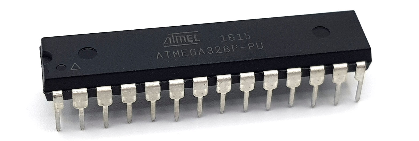
Pinout of the ATmega328P
For orientation, the pinout scheme of the ATmega328P:

The sleep modes of the ATmega328P
The Atmega328P offers six different sleep modes. Depending on the mode, more or less of its functions are sent to sleep. The remaining power consumption is correspondingly different.
If you send the ATmega328P to sleep, you must of course be able to wake it up again. Each mode has its selection of possible “wake-up calls”. In addition, it should be noted that the ATmega328P takes different times to wake up depending on the “sleep depth”.
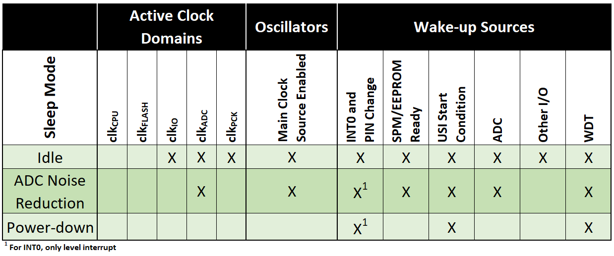
The following table provides an overview of which sleep modes are still activated and how to wake up the ATmega328P again. The good news is that the table is valid for a whole series of ATmegas.

Here is a short description of Sleep Modes. More information can be found in the data sheet.
- Idle: light sleep. You may need to switch off other components directly via PRR (coming later) so that the ATmega328P does not wake up unintentionally.
- ADC Noise Reduction: Even in this mode, many functions remain active. The ADC Noise Reduction Mode, as the name suggests, is also used to reduce noise in analog digital conversions. This allows a higher resolution to be achieved.
- Power-down: the most energy-saving deep sleep. Only external interrupts, TWI (Two Wire Interface -> I2C) or the watchdog interrupt can wake up the ATmega328P.
- Power-save: is similar to the power-down mode, but the Timer2 is still awake and could be operated via an external clock.
- Stand-by: the system oscillator is still running here. This mode is typically chosen when quick waking is necessary. Only six cycles are needed. It is important to know that an external quartz oscillator needs time in the millisecond range to provide a stable system clock.
- Extended Standby: Compared to the stand-by mode, the Timer2 is active.
Activating sleep modes
Control sleep modes via the SMCR
The sleep modes are controlled by corresponding entries in the Sleep Mode Control Register SMCR. The Bits SM0… SM2 set the mode, the SE bit (sleep enable) starts sleep mode.


Sleep modes using sleep.h functions
The short-notation
Not everyone likes to write into registers with instructions like SMCR |= (1<<SM0);. If you include the header file sleep.h, you can use less cryptic functions. How to do this, I show in the following sketch.
To wake up, I use the watchdog timer, which I set to 8 seconds. Details about the watchdog timer can be found here. I’ll discuss other wake-up methods later.
The sketch does the following:
- first wdt.h (for the watchdog timer) and sleep.h are included
- PD7 is set to OUTPUT
- the watchdog is set up
- The LED to PD7 starts for 3.5 seconds
- this serves only as an “I-am-awake-sign”
- I chose 3.5 seconds to allow my sluggish multimeter to measure the power consumption reliably
- after another 3.5 seconds, the watchdog timer is reset
- the sleep mode is selected with
set_sleep_mode(...), in this case power-down sleep_mode()starts sleep mode- after 8 seconds, the watchdog wakes up the Atmega328P; the interrupt service routine (ISR) is empty, but it still needs to be included in the sketch
- The sketch resumes its work directly after
sleep_mode()
#include <avr/wdt.h>
#include <avr/sleep.h>

void setup(){
  DDRD = (1<<PD7); // equals (roughly) pinMode(7, OUTPUT);
  watchdogSetup();
}

void loop(){
  PORTD |= (1<<PD7);  // equals (roughly) digitalWrite(7, HIGH);
  delay(3500);
  PORTD &= ~(1<<PD7); // equals (roughly) digitalWrite(7, LOW);
  delay(3500);
  wdt_reset();

  set_sleep_mode(SLEEP_MODE_PWR_DOWN); // choose power down mode
//  set_sleep_mode(SLEEP_MODE_PWR_SAVE); // choose power save mode
//  set_sleep_mode(SLEEP_MODE_STANDBY); // choose external standby power mode
//  set_sleep_mode(SLEEP_MODE_EXT_STANDBY); // choose external standby power mode
//  set_sleep_mode(SLEEP_MODE_IDLE); // did not work like this!
//  set_sleep_mode(SLEEP_MODE_ADC); // choose ADC noise reduction mode
//  sleep_bod_disable();  // optional brown-out detection switch off

  sleep_mode(); // sleep now!
}

void watchdogSetup(void){
  cli();
  wdt_reset();
  WDTCSR |= (1<<WDCE) | (1<<WDE);
  WDTCSR = (1<<WDIE) | (0<<WDE) | (1<<WDP3) | (1<<WDP0);  // 8s / interrupt, no system reset
  sei();
}

ISR(WDT_vect){//put in additional code here
}
For other Sleep Modes, simply uncomment the corresponding lines. Try idle mode. You will see that it is not working and the LED flashes with at a frequency of 3.5 s. Idle is a kind of light sleep and from such you wake up easily. We’ll come to see how you can prevent that.
And now try to swap lines 10 and 12. The LED now lights up while the ATmega328P is asleep, as all register contents are preserved during the sleep phase, including the port registers.
The more detailed spelling
The function sleep_mode(); corresponds to the sequence of commands:
sleep_enable();
sleep_cpu();
sleep_disable();
By the way, this is defined in sleep.h. You can find the file here: “Program Files (x86)\Arduino\hardware\tools\avr\avr\include\avr\sleep.h”. Don’t be sorry to look in.
It is safer if you use the more detailed command sequence and switch off all interrupts before sleep_enable() using cli(). Before sleep_cpu() you activate the interrupts again with sei(). Without the intermittent shutdown, interrupts can “collide” with unpredictable consequences. This is particularly important when further commands are inserted between sleep_enable() and sleep_cpu(), and that is exactly what we will do soon.
But for now, the sketch looks like this:
#include <avr/wdt.h>
#include <avr/sleep.h>

void setup(){
  DDRD = (1<<PD7); // equals (roughly) pinMode(7, OUTPUT);
  watchdogSetup();
}

void loop(){
  PORTD |= (1<<PD7);  // equals (roughly) digitalWrite(7, HIGH);
  delay(3500);
  PORTD &= ~(1<<PD7); // equals (roughly) digitalWrite(7, LOW);
  delay(3500);
  wdt_reset();

    set_sleep_mode(SLEEP_MODE_PWR_DOWN); // choose power down mode
//  set_sleep_mode(SLEEP_MODE_PWR_SAVE); // choose power save mode
//  set_sleep_mode(SLEEP_MODE_STANDBY); // choose external standby power mode
//  set_sleep_mode(SLEEP_MODE_EXT_STANDBY); // choose external standby power mode
//  set_sleep_mode(SLEEP_MODE_IDLE); // did not work!
//  set_sleep_mode(SLEEP_MODE_ADC); // choose ADC noise reduction mode

  cli(); // deactivate interrupts
  sleep_enable(); // sets the SE (sleep enable) bit
  sei(); //
  sleep_cpu(); // sleep now!!
  sleep_disable(); // deletes the SE bit
}

void watchdogSetup(void){
  cli();
  wdt_reset();
  WDTCSR |= (1<<WDCE) | (1<<WDE);
  WDTCSR = (1<<WDIE) | (0<<WDE) | (1<<WDP3) | (1<<WDP0);  // 8s / interrupt, no system reset
  sei();
}

ISR(WDT_vect){//put in additional code here
}
“Register fans” can replace lines 23 to 27 by:
SMCR |= (1<<SM1); // power down sleep mode
cli();
SMCR |= (1<<SE); // sleep_enable();
sei();
asm("SLEEP"); // sleep_cpu();
SMCR &= ~(1<<SE); // sleep_disable();
Less easy to read but nice in its brevity.
Benefits of the sleep modes – some measurements
I uploaded the last sketch on the Arduino UNO, the standalone ATmega328P and the ATtiny85, ran it using different clocks and measured the power consumption in the sleep phase. In some cases I uploaded the sketch using the Arduino IDE (as described in the last post), in the other cases I used Atmel (Microchip) Studio.
These values only apply to the conditions I have selected! Further measures (e.g. switching off the ADC) can achieve even more.

Some results were as expected, others not:
- The Arduino UNO uses a lot of power because of its peripherals on the board (e.g. the power LED).
- The idle mode consumes the most electricity in standalone operation.
- Power-down sleep mode consumes the least power.
- It makes an amazing difference for power-down mode whether the sketch is uploaded via Arduino IDE or Atmel Studio. This is because the Arduino board package switches on certain functions by default, which must be explicitly switched off for energy-efficient sleep. We’ll get to that.
- In power-down mode, there is no difference at different clock frequencies since the system clock is switched off.
- Using an ATtiny85 saves a lot of power.
Further energy-saving potentials
Saving energy with the Power Reduction Register
Depending on the sleep mode and the desired wake-up method, you can reduce power consumption even further by manually shutting off some components. This is controlled by the Power Reduction Register PRR:

Bits that are set switch off the corresponding component:
- PRTWI: switches off the Two Wire Interface (I2C). After waking up, it must be reinitialized.
- PRTIM2: turns off Timer2 in synchronous mode.
- PRTIM0/PRTIM1: these bits control Timer0 and Timer1.
- The Timers0/1/2 continue their work after waking up without any further action
- PRSPI: turns off the SPI interface. SPI must be reinitialized after waking up.
- PRUSART0: turns off the serial port, i.e. RX/TX (Universal Synchronous and Asynchronous serial Receiver and Transmitter). The USART interface must be reinitialized after waking up.
- PRADC: switches off the ADC
- To switch off the ADC, you must first deactivate it (line 18)
You don’t have to use binary operations to set the bits of your choice (although that’s not really hard). For this purpose, there are functions defined in the header file power.h. In the following sketch you will find the (self-explanatory) functions in lines 28 to 35.
To avoid fluctuating pin states during sleep, it is best to set the pins to OUTPUT/LOW (line 6-11).
#include <avr/wdt.h>
#include <avr/sleep.h>
#include <avr/power.h>

void setup(){
  DDRB = 0;
  DDRC = 0;
  DDRD = 0;
  PORTB = 0;
  PORTC = 0;
  PORTD = 0;

  watchdogSetup();
}

void loop(){
  delay(5000);
  ADCSRA = 0; // disable ADC
  set_sleep_mode(SLEEP_MODE_PWR_DOWN); // choose power down mode
//  set_sleep_mode(SLEEP_MODE_PWR_SAVE); // choose power save mode
//  set_sleep_mode(SLEEP_MODE_STANDBY); // choose external standby power mode
//  set_sleep_mode(SLEEP_MODE_EXT_STANDBY); // choose external standby power mode
//  set_sleep_mode(SLEEP_MODE_IDLE); // did not work!
//  set_sleep_mode(SLEEP_MODE_ADC); // choose ADC noise reduction mode

  cli(); // deactivate interrupts

//  power_usart0_disable();
//  power_spi_disable();
//  power_timer0_disable();
//  power_timer1_disable();
//  power_timer2_disable();
//  power_twi_disable();
//  power_adc_disable();
//  power_all_disable (); // short summary of the former six lines

  sleep_enable(); // sets the SE (sleep enable) bit
  sleep_bod_disable(); // disable brown-out detector


  sei(); //
  sleep_cpu(); // sleep now!! // no wake up option selected

  sleep_disable();
  power_all_enable();
}

void watchdogSetup(void){
  cli();
  wdt_reset();
  WDTCSR |= (1<<WDCE) | (1<<WDE);
  WDTCSR = (1<<WDIE) | (0<<WDE) | (1<<WDP3) | (1<<WDP0);  // 8s / interrupt, no system reset
  sei();
}

ISR(WDT_vect){//put in additional code here
}
With this sketch I was able to reduce the current consumption at 5 V supply voltage to 6.3 µA. If I also switched off the watchdog, it went down to 0.28 µA. However, the ATmega328 then no longer wakes up at all. Alternatively, I tried a pin change interrupt as a wake-up method. This resulted in a current consumption of 0.71 µA – not too bad either.
As you can see, I have not used any of the options provided by the Power Reduction Register in this sketch. This was not necessary because the components were either not activated or were switched off in power-down mode anyway. The main additional saving compared to the previous sketch was switching off the ADC using ADCSRA = 0.
If you are not sure what was activated in wake mode or not, it is better to switch off more than too little. However, you should not switch off anything that you need to wake up and you should not forget to switch the components back on again.
Turning off the Brown-Out Detector (BOD)
What is a BOD?
In case of a sudden, complete power failure, one speaks of a blackout. I think everyone knows this expression. A brown-out, on the other hand, is when the supply voltage of the microcontroller slips below a minimum level. Typically, this happens when the battery running your project drains. A microcontroller that gets too little voltage does completely unpredictable things. The microcontroller itself does not necessarily take any damage. But if the devices it controls do strange things, that might become critical. That’s why most microcontrollers have a Brown-Out Detector (BOD). This compares the operating voltage with a fixed trigger level. If this level is exceeded, a reset is triggered to protect the system. However, for some applications, a brownout may be unproblematic.
How do I turn off the BOD?
With the picoPower variants of the AVR microcontrollers, the Brown-Out detector can be switched off. You can recognize the picoPower models by the “P” in the name, e.g. the ATmega328P. The MCU Control Register MCUCR controlls the BOD:

The following bits are relevant:
- BODS: BOD Sleep
- BODSE: BOD Sleep Enable
Both bits must be set in a certain sequence to turn off the BOD. It is easier using the function sleep_bod_disable() which is defined in sleep.h. In the last sketch (idle_mode_enable.ino) I had already inserted the function in line 33, but not yet explained and commented out.
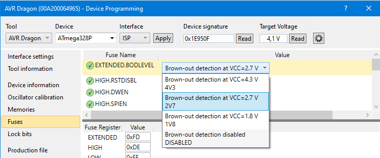
Alternatively, if you use programs like Atmel Studio, you can also control the BOD via the corresponding fuse bits (BODLEVEL). Settings 4.3 V, 2.7 V, 1.8 V, or “disabled” are available.
According to my measurements, turning off the BOD in the Sleep Mode Power-down saves another 8 µA of power. Doesn’t sound much, but in a year it’s about 70 mAh.
Lowering the clock frequency
In continuous awake mode, lowering the clock frequency results in a considerable saving (see Table 1). However, you have seen that the power consumption of the microcontroller is frequency-independent, at least in power-down mode. If you send the microcontroller to sleep and only wake it up briefly from time to time to do a few things, it may be better to select a high clock frequency. The reason for this is that things are done faster at high clock speeds. The speed overcompensates for the higher power consumption. If you use delays, things are different again. There is an interesting discussion about this topic on mikrocontroller.net.
Lowering the operating voltage
A microcontroller acts like a capacitor or – more exact – like many small capacitors and their charge depends on the operating voltage. This is called parasitic capacities. In addition, there are leakage currents, e.g. from conductor track to another.
In power-down mode, I could reduce the power consumption of the ATmega328P from 0.15 mA (programmed via Arduino IDE) to 0.12 mA when I reduced the voltage from 5 to 3.3 volts. More information and comparative values can be found here.
Other wake-up methods
In previous examples, the watchdog was our alarm clock for the ATmega328P. I would now like to mention two other methods.
Waking up via external interrupt
Using Arduino functions
In the following sketch, the ATmega328P is awakened by external interrupts. For this purpose, I have attached a pushbutton to INT0 (PD2, Pin4 = Arduino Pin 2), which generates a HIGH signal when pressed. Each time the button is pressed, the ATmega328P wakes up, the LED lights up for 1 second, then the ATmega328P settles down again.
With the Arduino functions, the interrupt can be easily set up. It is advisable to deactivate the interrupt after waking up so that it is not triggered several times, for example due to bouncing of the pushbutton. I have used the short sleep_mode() function here to draw attention to the relevant things.
#include <avr/sleep.h>

void setup(){
  DDRD = (1<<PD7);
}

void loop(){
  PORTD |= (1<<PD7);
  delay(1000);
  PORTD &= ~(1<<PD7);
  attachInterrupt(digitalPinToInterrupt(2), intRoutine, RISING);

  set_sleep_mode(SLEEP_MODE_PWR_DOWN); // choose power down mode
  sleep_mode(); // sleep now!
}

void intRoutine(){
  detachInterrupt(2); // external interrupt disable (INT0)
}
Programming in C
You can also write directly into the relevant registers, which is not really difficult. In the EICRA Register (External Interrupt Control Register A), you set the conditions for the interrupt.


In the EIMSK (External Interrupt Mask Register) the interrupt is activated:

Here’s what the sketch looks like:
#include <avr/sleep.h>

void setup(){
  DDRD = (1<<PD7);
  EICRA |= (1<<ISC01)|(1<<ISC00); // interrupt on rising edge of INT0
}

void loop(){
  PORTD |= (1<<PD7);
  delay(1000);
  PORTD &= ~(1<<PD7);
  EIMSK |= (1<<INT0); // external interrupt enable on INT0

  set_sleep_mode(SLEEP_MODE_PWR_DOWN); // choose power down mode
  sleep_mode(); // sleep now!
}

// INT0 interrupt service routine
ISR(INT0_vect){
  EIMSK &= ~(1<<INT0); // external interrupt disable (INT0)
}
Wake up by Timer2
If you want to wake up the ATmega328P using a timer, you can do this with Timer2 in all sleep modes, except in power-down mode. Anyone who has read my posts about the 8-bit Timer0 and Timer2 and the 16-bit Timer1 knows that the Timer2 overflows in a relatively short time, even when using the maximum prescaler. I do not go into the details of the timer programming here again.
In the following example sketch, the Timer2 is set with the maximum prescaler. At a clock speed of 16 MHz, 16 mio/1024/256 = ~61 interrupts are triggered per second. To obtain an eight seconds rest phase, I added a counter that is incremented every time the MCU wakes up. Only after the 500th wake up the LED lights up. This equates to 500 / 61 = 8.2 seconds pause. One would think that waking up frequently leads to considerable surplus of power consumption. Surprisingly, I even found slightly less power consumption in the sleep phase compared to permanent sleep method using the watchdog timer (2.92 mA vs. 2.97 mA).
#include <avr/sleep.h>
#include <avr/power.h>
int counter = 0;

void setup(){
  DDRD = (1<<PD7);
  TCCR2A = 0x00; // Wave Form Generation Mode 0: Normal Mode, OC2A disconnected
  TCCR2B = (1<<CS22)|(1<<CS21)|(1<<CS20); // prescaler = 1024
  TIMSK2 = (1<<TOIE2);
}

void loop(){
  if(counter==500){
    TIMSK2 &= ~(1<<TOIE2);
    PORTD |= (1<<PD7);
    delay(1000);
    PORTD &= ~(1<<PD7);
    counter = 0;
  }
  TIMSK2 = (1<<TOIE2); // interrupt when TCNT2 is overflowed
  TCNT2 = 0;
  set_sleep_mode(SLEEP_MODE_PWR_SAVE); // choose power down mode
  //power_timer2_disable(); // if you uncomment the MCU will sleep forever
  sleep_mode(); // sleep now!
  counter++;
}

// TIMER2 interrupt service routine
ISR(TIMER2_OVF_vect){
}
Try and uncomment line 23. The ATmega328P then falls into a “sleeping beauty sleep” – but without a prince kissing it awake. Only a reset awakes it again.
Apply sleep modes to other AVR MCUs
As mentioned at the beginning, the ATmega328P is not necessarily the first choice for an energy-saving project. With the knowledge acquired here, however, it should not be a problem for you to send other AVRs to sleep. Look at the data sheet and search for “sleep mode”. For example, the sleep mode table for the ATtiny85 / 45 / 25 looks like:
There are three sleep modes available, which can be activated via the corresponding functions from sleep.h. Awakening via the timer is not possible. However, if you write to the registers directly, you have to be aware that they have different names or that e.g. the watchdog timer has different prescalers.
Acknowledgement
This time I used a lot of pictures of Pixabay. In detail, I would like to thank the hard-working photographers:
- christinak93 for the monkey
- takanashi66 for the flamingos
- Salmar for the bats
- Yves Yoseph for the tired biker
- Philip Barrington for the koala
- skeeze for the seal
- _freakwave_ for the cats
- Alexas_Fotos for the pig
- Sabine Lange for the baby
FYI:
I used the ATmega328P on a pro mini board for several battery powered led light projects where it wakes up by an touch controller attached to an interrupt.
I never got below around 250uA (LED and regulator removed of course).
And recently with a lot time for testing I found out, that using a different library instead of using sleep.h solved this issue for me.
I got around 16uA (tested at 5 volts an from 4.2V down to 3.2V @16Mhz with a LED driver and a touch controller attached)
What i used: https://github.com/rocketscream/Low-Power
This is all i used code wise:
”
#include “LowPower.h”
void sleep() // here we put the arduino to sleep
{
// Allow wake up pin to trigger interrupt on low.
attachInterrupt(0, wakeUp, LOW);
// Enter power down state with ADC and BOD module disabled.
// Wake up when wake up pin is low.
LowPower.powerDown(SLEEP_FOREVER, ADC_OFF, BOD_OFF);
// Disable external pin interrupt on wake up pin.
detachInterrupt(0);
// Do something here
// Example: Read sensor, data logging, data transmission.
}
void wakeUp() // here the interrupt is handled after wakeup
{
//execute code here after wake-up before returning to the loop() function
// timers and code using timers (serial.print and more…) will not work here.
//digitalWrite(LED, LOW);
}
”
This took me two years to find out especially because in my research there never came up a conclusive solution…
Hope it helps other people with the same issues…
Thank you! Will also try this.