
About the post
What are the benefits of an LTC6995? The internal timers of the AVR microcontrollers have a limited, maximum runtime. Depending on the model and clocking, their maximum periods are a few seconds, for some timers even less. If you want to cover longer periods, you need to introduce additional counters. I have handled this in my posts about Timer0/2, Sleep Modes and the Watchdog Timer.
I therefore wondered whether there are external timers or oscillators that work in the range of minutes or even hours – and with the LTC6995 I found what I was looking for. It covers a frequency range of 977 hertz down to 29.1 microhertz or – expressed in periods – from about one millisecond to 9.54 hours.
I will cover the following topics in this article:
- Technical features of the LTC6995
- The LTC6995 as oscillator
- Use as power-on reset timer
- General timer
- The LTC6995 as sleep mode “alarm clock”
- External Watchdog Timer
Technical features of the LTC6995
Design and versions

First the bad news for all breadboard developers: the LTC6995 is not available as “DIP” version, but only as an SMD component, namely as TSOT23 or as DFN. If you want to use it on a breadboard, you need to solder it to an adapter. Simply search for “SOT23 Adapter”, e.g. on Amazon. Soldering of SMD components is of course a certain challenge, but feasible. I found a guide here.
There are two versions of the LTC6995, the LTC6995-1 and the LTC6995-2. I will explain the difference further down below. I used the “-1 version” for this post, but I also refer to the “-2 version”.
In addition, there are other letters in the part encoding, for example I have the LTC6995CS6-1-TRMPBF. The “C” stands for the temperature range, “S6” for the TSOT23 design and TRMPBF for the packaging (Tape and Reel Mini). More information can be found in the data sheet. You can buy the LTC6995-1 e.g. on eBay or at Conrad for about 3 Euro plus shipping. The LTC6995-2 is harder to get. Mouser would be a source, but you have to pay 20 Euro shipping fee. Of course, this is only worthwhile for larger orders.
Alternatively, the LTC6995 is also available on a development/demonstration board called DC1562B-M. But that only makes sense if you are planning several projects with the LTC6995.
Technical data
- Period: 1 millisecond to 9.5 hours
- Supply voltage: 2.25 – 5.5 volts
- Needs only three resistors to be configured
- (Start) Output polarity selectable
- Maximum ouput current (or sink): 20 milliamperes
- Power consumption: 55 – 80 microamperes
- 500 microseconds start-up time
Pinout of the LTC6995
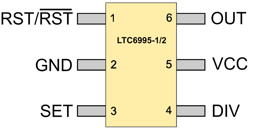
- VCC/GND: Power supply
- OUT: Output signal
- SET: here the frequency is set. The LTC6995 regulates SET to 1 volt. SET is connected to GND via a resistor. The current flow from SET to GND determines the frequency. In other words, the size of the resistor determines the frequency.
- DIV: the voltage which is applied to DIV sets the divider. The divider – as the name suggests – divides the frequency which set by the resistor connected to SET. There are eight dividers available: 20, 23, 26, … , 221. In addition, the start polarity of the output signal is set at DIV. Eight dividers with two possible start polarities results in 16 settings. To make these settings, a 4-bit A/D converter is internally connected to the DIV pin.
- RST: the reset pin restarts the timer. For the LTC6995-1 the pin is active-high, for the LTC6995-2 it is active-low.
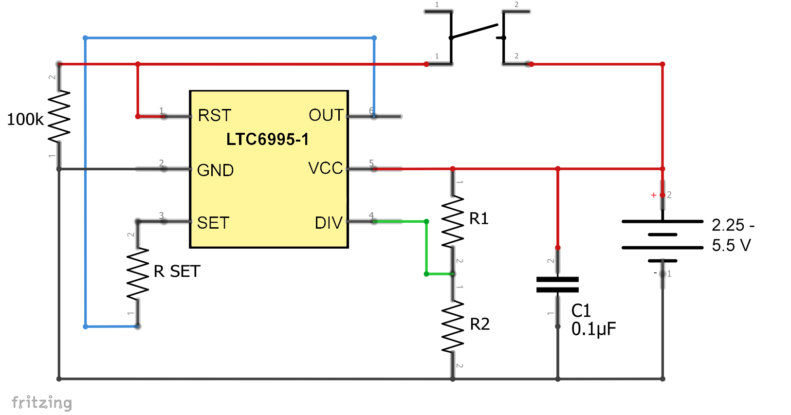
The LTC6995 as oscillator

The oscillator circuit is simple. RST is connected to GND for the LTC6995-1, and to VCC for the LTC6995-2. RSET sets the frequency. The voltage at DIV is set via a voltage divider (R1 and R2). The capacitor C1 is used to stabilize the supply voltage. At OUT you will receive a square wave signal with the desired frequency. To play, you can attach an LED to it (up to 20 mA).
Selection of resistors
First, determine how your square wave signal shall look like. Should it be HIGH or LOW when switching on or reset? To illustrate this:
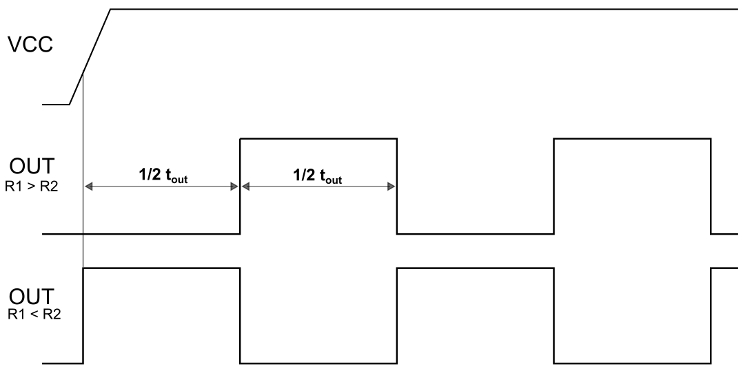
Then you choose the appropriate divcode from Table 1. The divcodes 0 – 7 provide a starting polarity LOW (0), 8 – 15 provide a starting polarity HIGH (1). Now you check which divcode covers the period (tOUT) you want. The areas overlap. For the lowest power consumption (on SET) you always choose the lowest possible divider NDIV.

In Table 1 you can choose the appropriate divcode and find the values for R1 and R2. The resistor values are the ideal values and sometimes quite unusual. You can help yourself by combining more common resistors. Minor deviations are not a problem because as mentioned before the evaluation of the voltage at DIV is managed by a 4-bit A/D converter.
RSET and tOUT are related as follows:
![\[ t_{out}\;[\text{ms}] =\frac{N_{DIV}\cdot R_{SET}\,[\text{k}\Omega]}{50\,[\text{k}\Omega]}\cdot1.024\,[\text{ms}] \]](https://wolles-elektronikkiste.de/wp-content/ql-cache/quicklatex.com-da9a816729dd5b966d7aa956732460ae_l3.png "Rendered by QuickLaTeX.com")
![\[ R_{SET}\,[\text{k}\Omega]=t_{out}\,[\text{ms}]\cdot \frac{50\,[\text{k}\Omega]}{N_{DIV}\cdot 1.024\,[\text{ms}]} \]](https://wolles-elektronikkiste.de/wp-content/ql-cache/quicklatex.com-459e39a3f138d6d44ae73aa9cc2b4165_l3.png "Rendered by QuickLaTeX.com")
In Table 1, in the last column, you find the formula for RSET, in which you only need to insert tOUT. The formula contains 1/2 tOUT, since this value is relevant for most applications, as you will see.
Practical verification of some values
I tried a few combinations and found the following results:
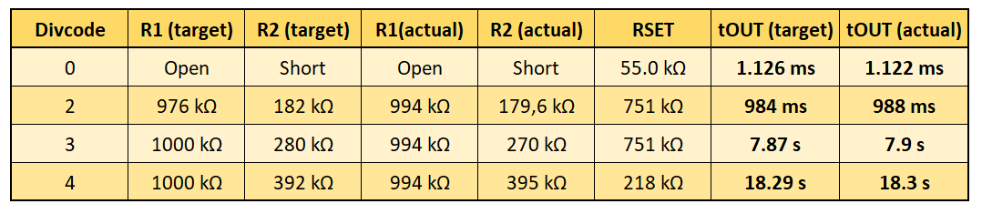
I determined the tOUT-periods which were in the range of seconds by attaching an LED to OUT and measuring 10 to 20 cycles with a stopwatch. I used an oscilloscope to test the first resistor combination in Table 2. Also in this range, near to the maximum frequency, the LTC6995’s provided a “clean” square wave signal:

The LTC6995 as power-on reset timer
What does power-on reset mean?
When switching on the supply voltage of circuits, it may take a little while for the voltage to stabilize. In this startup phase with undefined conditions, complex components such as microcontrollers and computers could do unforeseeable things. That’s why they have integrated internal Power-On Reset (POR) circuits. As long as the system does not have the required minimum voltage, the sensitive parts are held in reset mode. Systems that do not have a POR can be equipped with external PORs. The LTC6995 is suitable for this purpose. Even if you don’t care about PORs, please read on anyway because the circuits in the following sections built on the one used here.
Wiring

The difference between the POR circuit and the oscillator circuit is that SET is not connected to GND, but to OUT. For the divcodes 0-7, OUT is LOW at the beginning. Systems that are reset with a LOW signal can be kept in reset mode. After 1/2 tOUT, OUT goes HIGH and the controlled system starts.
If OUT is in HIGH state, no more current flows via SET. You may remember that SET is set to 1 volt. Since the timer is controlled by the current flowing out of SET, the timer is stopped so that no further reset signal can be generated.

Starting with OUT = HIGH, i.e. divcode 8-15, would not work because the timer stops immediately. For a system that is reset with a HIGH signal, the OUT signal must therefore be inverted.
Signal inversion
You can easily invert a signal or a logic level with an NPN transistor (e.g. BC547) and two resistors:

If the input level is LOW or GND, then the transistor is closed and the output level is HIGH or at VCC level. If the input level is HIGH, the transistor is open and the output level is drawn to LOW or GND.
General timer
The POR timer has done its duty when the system is running. A general timer is something you might want to use multiple times. For this purpose, the LTC6995 just needs to be reset.
On the LTC6995-1, RST is connected to GND via a pull-down resistor and can then be restarted with a HIGH signal. With the LTC6995-2 it is the same, only with reverse polarities (RST on HIGH and reset by LOW).
In the following circuit, a button is used for reset:
For example, you can build a lamp without a microcontroller that turns off (or turns on) after a certain time. Or you use the output of a sensor instead of the button and OUT triggers a reaction on its signal. If necessary, you can invert the OUT signal.
The LTC6995 as sleep mode alarm clock
In my last post I showed how to wake an ATmega328P or another microcontroller from sleep mode via external interrupts. With the LTC6995 you have a tool to let the microcontroller sleep undisturbed for long periods of time.
Wiring
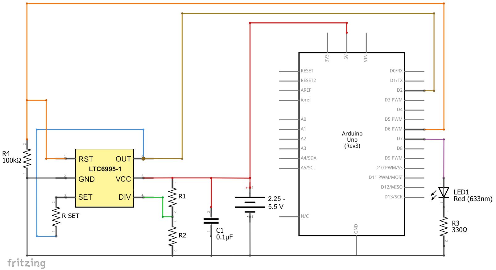
For the sleep mode alarm clock we use the previous circuit and replace the button with an I/O pin of the ATmega328P (here PD6). OUT is connected to an interrupt pin (here INT0).

Using the Arduino UNO, it looks like this:
An example sketch
I have two example sketches for you, but they are both doing the same. The first is using C commands, the second is using Arduino functions. A few comments on the sketches:
- First, the sleep header file is included.
- PD6 and PD7 (=Arduino UNO Pin 6 and 7) are set to output.
- An interrupt at INT0 (=Arduino UNO Pin 2) is set up; It is triggered with the rising flank.
- At the beginning of the main loop, the LED on PD7 lights up for a second – this is our “hello-I-am-wake” sign.
- Before the ATmega328P (or the Arduino UNO) is sent to sleep, the interrupt is activated and the LCT6995 is reset.
- The LCT6995 sends its wake-up signal after 1/2 tOUT.
- The interrupt routine disables the external interrupt.
If I were to go into more detail about sleep modes, it would go beyond the scope of the article. If necessary, visit my last post.
#include <avr/sleep.h>

void setup(){
  DDRD = (1<<PD7)|(1<<PD6); // PD6 und PD7 auf OUTPUT
  EICRA |= (1<<ISC01)|(1<<ISC00); // interrupt on rising edge of INT0
}

void loop(){
  PORTD |= (1<<PD7); // switch on LED
  _delay_ms(1000);
  PORTD &= ~(1<<PD7);
  EIMSK |= (1<<INT0); // external interrupt enable on INT0
  resetLTC6995();
  set_sleep_mode(SLEEP_MODE_PWR_DOWN); // choose power down mode
  sleep_mode(); // sleep now!
}

void resetLTC6995(){
  PORTD |= (1<<PD6);  // Reset Signal für den LTC6995-1
  _delay_ms(1);
  PORTD &= ~(1<<PD6);
}

// INT0 interrupt service routine
ISR(INT0_vect){
  EIMSK &= ~(1<<INT0); // external interrupt disable (INT0)
}
#include <avr/sleep.h>
const int ledPin = 7;
const int ltc6995ResetPin = 6;

void setup(){
  pinMode(ledPin, OUTPUT);
  pinMode(ltc6995ResetPin, OUTPUT);
}

void loop(){
  digitalWrite(ledPin, HIGH); // switch on LED
  delay(1000);
  digitalWrite(ledPin, LOW);
  attachInterrupt(digitalPinToInterrupt(2), intRoutine, RISING); //enable interrupt
  resetLTC6995();
  set_sleep_mode(SLEEP_MODE_PWR_DOWN); // choose power down mode
  sleep_mode(); // sleep now!
}

void resetLTC6995(){
  digitalWrite(ltc6995ResetPin, HIGH); // Reset Signal für den LTC6995-1
  delay(1);
  digitalWrite(ltc6995ResetPin, LOW);
}

// interrupt routine
void intRoutine(){
  detachInterrupt(2); // disable interrupt
}
The LTC6995 as external watchdog timer
I am not going into what a watchdog is and why it is needed. If necessary, check here.
The basic idea is this: The LTC6995 regularly sends a reset signal to the monitored system, unless the monitored system resets the LTC6995 beforehand.
First of all, I made a stupid mistake that I want to share with you. I thought I could just use the oscillator signal of the LTC6995 to reset. Divcode 8-15, then OUT is HIGH at the beginning and when it changes to LOW, there is a RESET. And in principle that’s true, but: OUT stays on LOW for a further period of 1/2 tOUT. This means that the microcontroller does not reset as long as the reset signal is active. I hope you can still follow my thoughts…
The solution: Self-reset of the LTC6955
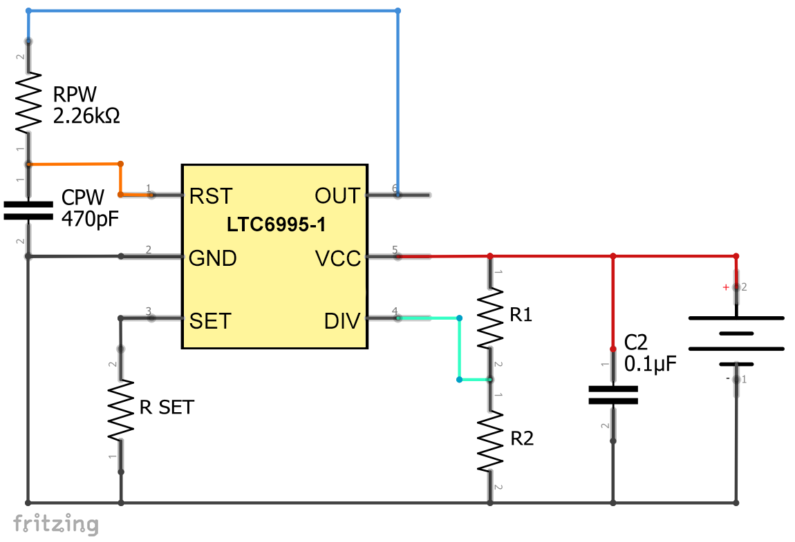
With the following circuit, the LTC6995-1 goes briefly to HIGH after 1/2 tOUT and then resets. However, this only works with the divcodes 0-7. The example with these RPW / CPW values are taken from the datasheet.
When using the LTC6995-2, you take the same circuit, but the divcodes 8-15. The polarity of OUT looks like this (not true to scale!):

tpulse is calculated for the LTC6995-1 according to the following formula (details in the data sheet):
![\[ t_{pulse}\,[\mu s]=\frac{R_{PW}\,[\text{k}\Omega]\cdot C_{PW}[\text{pF]}\cdot 0.942}{1000} \]](https://wolles-elektronikkiste.de/wp-content/ql-cache/quicklatex.com-66ddbcb94980f419e11596b0334737f5_l3.png "Rendered by QuickLaTeX.com")
RPW = 2.26 kOhm and CPW = 470 pF result in tpulse = 1 µs.
Since the ATmega328P or the Arduino UNO or other AVR MCUs are reset with a LOW signal, the OUT signal must still be inverted when using the LTC6995-1. The complete circuit looks like this (RPW and CPW I changed because I didn’t have the resistors and capacitors available):

An example sketch
To test the following example sketch, I have chosen the following resistors:
- R1 = 994 kOhm
- R2 = 395 kOhm
- RSET = 218.1 kOhm
This corresponds to Divcode 4 and 1/2 tOUT is about 9.15 seconds. After a reset of the LTC6995-1 you have 9.15 seconds to reset it again in this configuration, otherwise the LTC6995-1 resets the microcontroller. A reset race, so to speak.
The example sketch (again once in C and once “in Arduino”) does the following:
- PD6 and PD7 (or Arduino pin 6 and 7) are set to OUTPUT
- The LED on PD7 lights up as a sign for the start of the sketch for one second
- Before going into the main loop, the LTC6995-1 is reset again (
watchdogReset()) - if the watchdog reset command is commented out as here, the ATmega328P is reset again and again after 9.15 seconds by the LTC6995-1, which you can see by the glow of the LED
- if you uncomment the watchdog reset command, there will be no reset of the ATmega328P – the LED stays off
void setup(){
  DDRD = (1<<PD7)|(1<<PD6);
  PORTD |= (1<<PD7);
  _delay_ms(1000);
  PORTD &= ~(1<<PD7);
  watchdogReset();
}

void loop(){
//  _delay_ms(8000);
//  watchdogReset();
}

void watchdogReset(){
  PORTD |= (1<<PD6);
  _delay_ms(1);
  PORTD &= ~(1<<PD6);
}
const int ledPin = 7;
const int wdResetPin = 6;

void setup(){
  pinMode(ledPin, OUTPUT);
  pinMode(wdResetPin, OUTPUT);
  digitalWrite(ledPin, HIGH);
  delay(1000);
  digitalWrite(ledPin,LOW);
  watchdogReset();
}

void loop(){
//  delay(8000);
//  watchdogReset();
}

void watchdogReset(){
  digitalWrite(wdResetPin,HIGH);
  delay(1);
  digitalWrite(wdResetPin,LOW);
}