
About the post
With an HX711 module and a load cell, it is easy to build an amazingly exact scale. In this article, I would like to show how this works in principle.
My goal was to achieve the same functionality as my digital kitchen scale:
- Output of the weight on a display
- Only one button to turn on and for tare
- Automatic shutdown after a certain time
The article is structured as follows:
- What you need
- The measuring principle
- Installing the load cell
- Using the HX711 ADC Library
- Output via an OLED display
- How to send the scale to sleep
- How the balance can turn itself off completely
What you need

To build the scale, you need a load cell and an HX711 module. You can buy both as a kit. If you search for “HX711 load cell” on Amazon or eBay, for example, you’ll get dozens of offers for a few euros. Select a load cell with the weight range that is right for you. For this post, I chose a 2 kg cell.
That being said, I can’t provide you with a detailed shopping list because it depends too much on your specific wants and needs. I recommend reading first this article and then decide for yourself.
The measuring principle
The load cell is slightly bent by the weight of the load to be weighed. Under the white glue there are four strain gauges which build a Wheatstone bridge. Their resistance value changes with the degree of elongation, i.e. with the weight. The resistance generates a voltage drop, which in turn is evaluated with an A/D converter. In my blog post about strain gauges, I explain the details.
The change in voltage drop with increasing weight is small. I measured a few millivolts per kilogram. The A/D converter of an Arduino UNO or an ATmega328P is not suitable for this purpose. The HX711, on the other hand, has an impressive resolution of 24 bits (= 16,777,216).
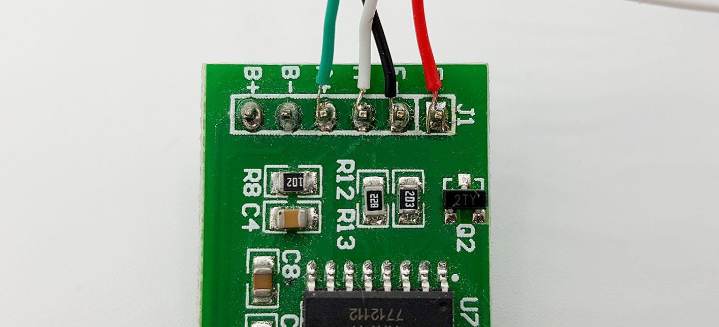
The HX711 itself is actually the sixteen pin chip on the module. Since it still needs a few parts to work properly, it is convenient to use the ready-to-use module. If you are interested in more technical details of the HX711, you find a data sheet here.
Installing the load cell
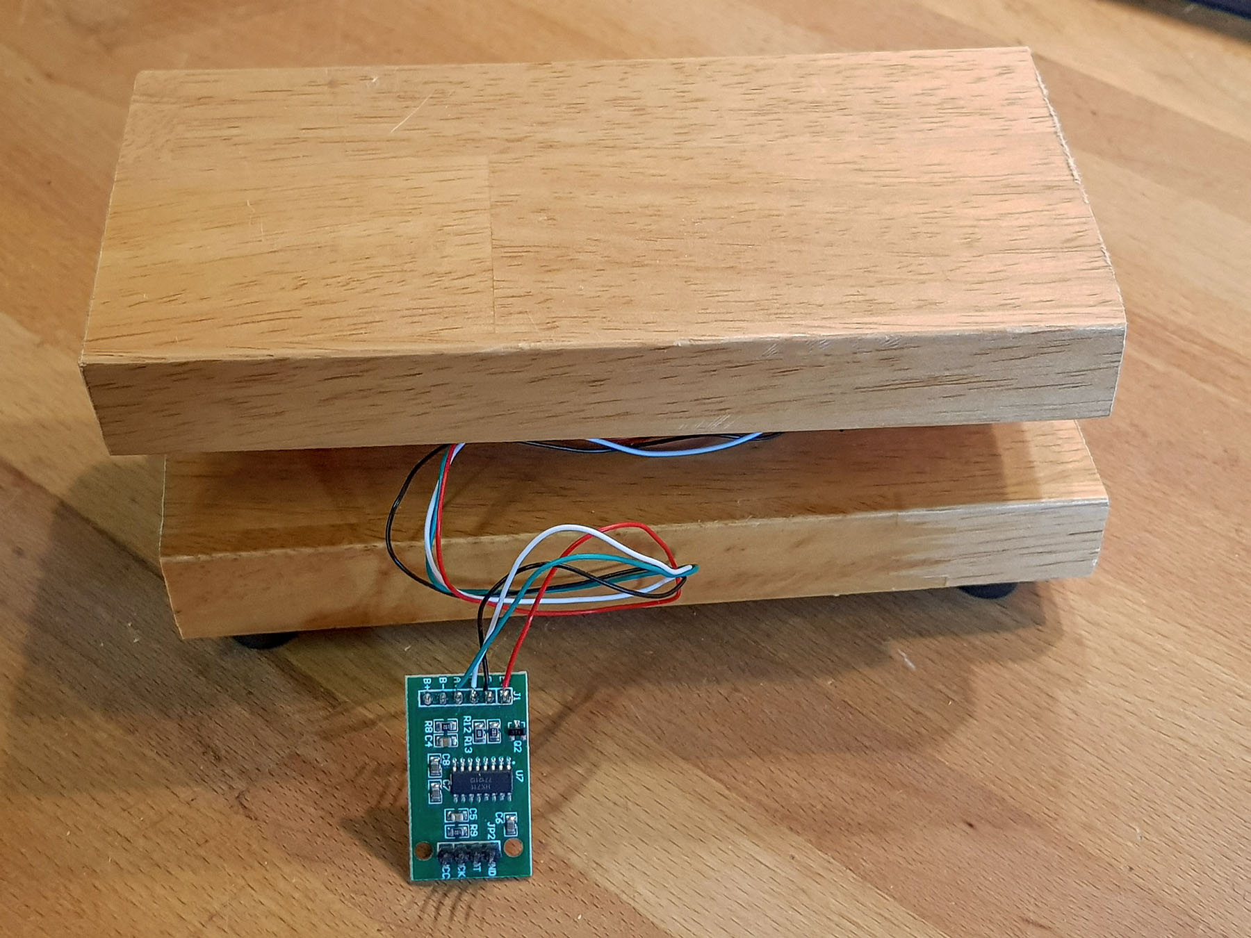
You can’t avoid some tinkering. The load cell must be installed in a way that it will bend under weight. I just took a board which I found in my cellar and sawed off two equally sized pieces. I placed the load cell between the boards with spacers.

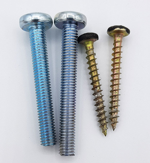
I drilled two holes through the bottom board and attached the load cell with two M5 screws. In addition, I added some rubber spacers to the underside.

For the other side, M4 screws are actually provided. However, in order to have a smooth support surface for the weighing material, I did not want to pierce the upper board. That’s why I just took a few wood screws.
Connect the load cell cables to the module as follows:
- Red on E+
- Black on E-
- White on A-
- Green on A+
Using the HX711 ADC Library
I used Olav Kallhovd’s HX711 ADC library to control the module. You can download it directly from Github here or install it via the Arduino IDE library manager.
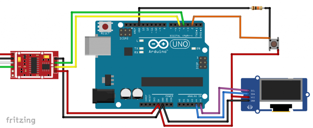
HX711 Basic wiring
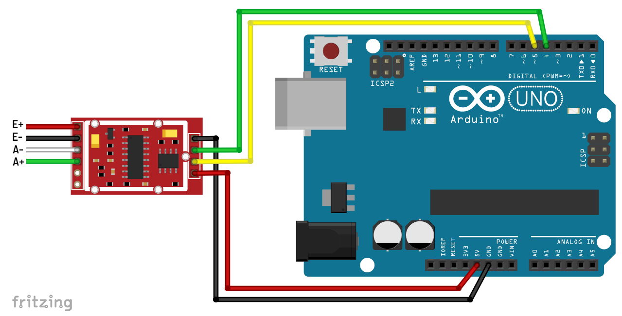
The module can be operated with voltages between 2.6 and 5.5 volts. The module is < quite economical. Its power consumption is 1.5 milliamperes. The DT pin is connected to the Arduino Pin 4, SCK is attached to pin 5. You can choose other pins if you want.
Calibration of the balance
To calibrate, you need an object with a known weight. The weight should be exactly known to the gram and not too small. It is best to take a second balance.
The beauty of the library used here is that it makes life – or at least the balance calibration 😉 – easy for you. Select the “Calibration.ino” sketch from the library’s examples. I have printed it here unchanged:
/*
   -------------------------------------------------------------------------------------
   HX711_ADC
   Arduino library for HX711 24-Bit Analog-to-Digital Converter for Weight Scales
   Olav Kallhovd sept2017
   -------------------------------------------------------------------------------------
*/

/*
   This example file shows how to calibrate the load cell and optionally store the calibration
   value in EEPROM, and also how to change the value manually.
   The result value can then later be included in your project sketch or fetched from EEPROM.

   To implement calibration in your project sketch the simplified procedure is as follow:
       LoadCell.tare();
       //place known mass
       LoadCell.refreshDataSet();
       float newCalibrationValue = LoadCell.getNewCalibration(known_mass);
*/

#include <HX711_ADC.h>
#if defined(ESP8266)|| defined(ESP32) || defined(AVR)
#include <EEPROM.h>
#endif

//pins:
const int HX711_dout = 4; //mcu > HX711 dout pin
const int HX711_sck = 5; //mcu > HX711 sck pin

//HX711 constructor:
HX711_ADC LoadCell(HX711_dout, HX711_sck);

const int calVal_eepromAdress = 0;
unsigned long t = 0;

void setup() {
  Serial.begin(57600); delay(10);
  Serial.println();
  Serial.println("Starting...");

  LoadCell.begin();
  //LoadCell.setReverseOutput(); //uncomment to turn a negative output value to positive
  unsigned long stabilizingtime = 2000; // preciscion right after power-up can be improved by adding a few seconds of stabilizing time
  boolean _tare = true; //set this to false if you don't want tare to be performed in the next step
  LoadCell.start(stabilizingtime, _tare);
  if (LoadCell.getTareTimeoutFlag() || LoadCell.getSignalTimeoutFlag()) {
    Serial.println("Timeout, check MCU>HX711 wiring and pin designations");
    while (1);
  }
  else {
    LoadCell.setCalFactor(1.0); // user set calibration value (float), initial value 1.0 may be used for this sketch
    Serial.println("Startup is complete");
  }
  while (!LoadCell.update());
  calibrate(); //start calibration procedure
}

void loop() {
  static boolean newDataReady = 0;
  const int serialPrintInterval = 0; //increase value to slow down serial print activity

  // check for new data/start next conversion:
  if (LoadCell.update()) newDataReady = true;

  // get smoothed value from the dataset:
  if (newDataReady) {
    if (millis() > t + serialPrintInterval) {
      float i = LoadCell.getData();
      Serial.print("Load_cell output val: ");
      Serial.println(i);
      newDataReady = 0;
      t = millis();
    }
  }

  // receive command from serial terminal
  if (Serial.available() > 0) {
    char inByte = Serial.read();
    if (inByte == 't') LoadCell.tareNoDelay(); //tare
    else if (inByte == 'r') calibrate(); //calibrate
    else if (inByte == 'c') changeSavedCalFactor(); //edit calibration value manually
  }

  // check if last tare operation is complete
  if (LoadCell.getTareStatus() == true) {
    Serial.println("Tare complete");
  }

}

void calibrate() {
  Serial.println("***");
  Serial.println("Start calibration:");
  Serial.println("Place the load cell an a level stable surface.");
  Serial.println("Remove any load applied to the load cell.");
  Serial.println("Send 't' from serial monitor to set the tare offset.");

  boolean _resume = false;
  while (_resume == false) {
    LoadCell.update();
    if (Serial.available() > 0) {
      if (Serial.available() > 0) {
        char inByte = Serial.read();
        if (inByte == 't') LoadCell.tareNoDelay();
      }
    }
    if (LoadCell.getTareStatus() == true) {
      Serial.println("Tare complete");
      _resume = true;
    }
  }

  Serial.println("Now, place your known mass on the loadcell.");
  Serial.println("Then send the weight of this mass (i.e. 100.0) from serial monitor.");

  float known_mass = 0;
  _resume = false;
  while (_resume == false) {
    LoadCell.update();
    if (Serial.available() > 0) {
      known_mass = Serial.parseFloat();
      if (known_mass != 0) {
        Serial.print("Known mass is: ");
        Serial.println(known_mass);
        _resume = true;
      }
    }
  }

  LoadCell.refreshDataSet(); //refresh the dataset to be sure that the known mass is measured correct
  float newCalibrationValue = LoadCell.getNewCalibration(known_mass); //get the new calibration value

  Serial.print("New calibration value has been set to: ");
  Serial.print(newCalibrationValue);
  Serial.println(", use this as calibration value (calFactor) in your project sketch.");
  Serial.print("Save this value to EEPROM adress ");
  Serial.print(calVal_eepromAdress);
  Serial.println("? y/n");

  _resume = false;
  while (_resume == false) {
    if (Serial.available() > 0) {
      char inByte = Serial.read();
      if (inByte == 'y') {
#if defined(ESP8266)|| defined(ESP32)
        EEPROM.begin(512);
#endif
        EEPROM.put(calVal_eepromAdress, newCalibrationValue);
#if defined(ESP8266)|| defined(ESP32)
        EEPROM.commit();
#endif
        EEPROM.get(calVal_eepromAdress, newCalibrationValue);
        Serial.print("Value ");
        Serial.print(newCalibrationValue);
        Serial.print(" saved to EEPROM address: ");
        Serial.println(calVal_eepromAdress);
        _resume = true;

      }
      else if (inByte == 'n') {
        Serial.println("Value not saved to EEPROM");
        _resume = true;
      }
    }
  }

  Serial.println("End calibration");
  Serial.println("***");
  Serial.println("To re-calibrate, send 'r' from serial monitor.");
  Serial.println("For manual edit of the calibration value, send 'c' from serial monitor.");
  Serial.println("***");
}

void changeSavedCalFactor() {
  float oldCalibrationValue = LoadCell.getCalFactor();
  boolean _resume = false;
  Serial.println("***");
  Serial.print("Current value is: ");
  Serial.println(oldCalibrationValue);
  Serial.println("Now, send the new value from serial monitor, i.e. 696.0");
  float newCalibrationValue;
  while (_resume == false) {
    if (Serial.available() > 0) {
      newCalibrationValue = Serial.parseFloat();
      if (newCalibrationValue != 0) {
        Serial.print("New calibration value is: ");
        Serial.println(newCalibrationValue);
        LoadCell.setCalFactor(newCalibrationValue);
        _resume = true;
      }
    }
  }
  _resume = false;
  Serial.print("Save this value to EEPROM adress ");
  Serial.print(calVal_eepromAdress);
  Serial.println("? y/n");
  while (_resume == false) {
    if (Serial.available() > 0) {
      char inByte = Serial.read();
      if (inByte == 'y') {
#if defined(ESP8266)|| defined(ESP32)
        EEPROM.begin(512);
#endif
        EEPROM.put(calVal_eepromAdress, newCalibrationValue);
#if defined(ESP8266)|| defined(ESP32)
        EEPROM.commit();
#endif
        EEPROM.get(calVal_eepromAdress, newCalibrationValue);
        Serial.print("Value ");
        Serial.print(newCalibrationValue);
        Serial.print(" saved to EEPROM address: ");
        Serial.println(calVal_eepromAdress);
        _resume = true;
      }
      else if (inByte == 'n') {
        Serial.println("Value not saved to EEPROM");
        _resume = true;
      }
    }
  }
  Serial.println("End change calibration value");
  Serial.println("***");
}
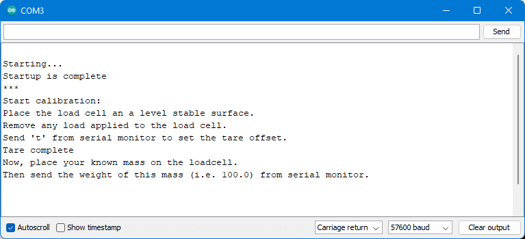
Start the sketch and open the serial monitor. Wait until the following message is displayed:
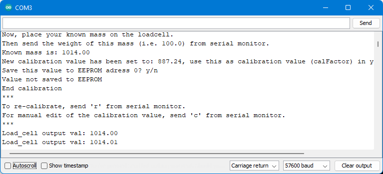
Then take the weight, put it on the scale, enter the weight in grams and press Enter or click on Send. Write down the “calibration value” or have it written in the EEPROM of the Arduino UNO. The balance is now calibrated and provides the weight.
If the weight drifts a little, then repeat the calibration and try a longer “stabilizing time” (line 145).
Regular operation of the HX711 balance
After calibrating the scale, you can now go into regular operation. The sketch “Read_1x_load_cell.ino” is a good starting point for this. You only have to enter your calibration factor in line 44 or – if you have it in the EEPROM – uncomment line 48. Otherwise, the sketch works “out of the box”. If you are using an ESP8266, you will also need to uncomment on line 46.
For the tare, you enter a “t” in the serial monitor.
/*
   -------------------------------------------------------------------------------------
   HX711_ADC
   Arduino library for HX711 24-Bit Analog-to-Digital Converter for Weight Scales
   Olav Kallhovd sept2017
   -------------------------------------------------------------------------------------
*/

/*
   Settling time (number of samples) and data filtering can be adjusted in the config.h file
   For calibration and storing the calibration value in eeprom, see example file "Calibration.ino"

   The update() function checks for new data and starts the next conversion. In order to acheive maximum effective
   sample rate, update() should be called at least as often as the HX711 sample rate; >10Hz@10SPS, >80Hz@80SPS.
   If you have other time consuming code running (i.e. a graphical LCD), consider calling update() from an interrupt routine,
   see example file "Read_1x_load_cell_interrupt_driven.ino".

   This is an example sketch on how to use this library
*/

#include <HX711_ADC.h>
#if defined(ESP8266)|| defined(ESP32) || defined(AVR)
#include <EEPROM.h>
#endif

//pins:
const int HX711_dout = 4; //mcu > HX711 dout pin
const int HX711_sck = 5; //mcu > HX711 sck pin

//HX711 constructor:
HX711_ADC LoadCell(HX711_dout, HX711_sck);

const int calVal_eepromAdress = 0;
unsigned long t = 0;

void setup() {
  Serial.begin(57600); delay(10);
  Serial.println();
  Serial.println("Starting...");

  LoadCell.begin();
  //LoadCell.setReverseOutput(); //uncomment to turn a negative output value to positive
  float calibrationValue; // calibration value (see example file "Calibration.ino")
  calibrationValue = 887.24; // uncomment this if you want to set the calibration value in the sketch
#if defined(ESP8266)|| defined(ESP32)
  //EEPROM.begin(512); // uncomment this if you use ESP8266/ESP32 and want to fetch the calibration value from eeprom
#endif
  //EEPROM.get(calVal_eepromAdress, calibrationValue); // uncomment this if you want to fetch the calibration value from eeprom

  unsigned long stabilizingtime = 2000; // preciscion right after power-up can be improved by adding a few seconds of stabilizing time
  boolean _tare = true; //set this to false if you don't want tare to be performed in the next step
  LoadCell.start(stabilizingtime, _tare);
  if (LoadCell.getTareTimeoutFlag()) {
    Serial.println("Timeout, check MCU>HX711 wiring and pin designations");
    while (1);
  }
  else {
    LoadCell.setCalFactor(calibrationValue); // set calibration value (float)
    Serial.println("Startup is complete");
  }
}

void loop() {
  static boolean newDataReady = 0;
  const int serialPrintInterval = 0; //increase value to slow down serial print activity

  // check for new data/start next conversion:
  if (LoadCell.update()) newDataReady = true;

  // get smoothed value from the dataset:
  if (newDataReady) {
    if (millis() > t + serialPrintInterval) {
      float i = LoadCell.getData();
      Serial.print("Load_cell output val: ");
      Serial.println(i);
      newDataReady = 0;
      t = millis();
    }
  }

  // receive command from serial terminal, send 't' to initiate tare operation:
  if (Serial.available() > 0) {
    char inByte = Serial.read();
    if (inByte == 't') LoadCell.tareNoDelay();
  }

  // check if last tare operation is complete:
  if (LoadCell.getTareStatus() == true) {
    Serial.println("Tare complete");
  }
}
Maybe you don’t want to tare the balance when you switch it on? Then, in line 48, change the value of _tare to false. You will then get a “fantasy value” as a measurement result. Write down this value and subtract it from future measurement results. You have frozen the tare, so to speak.
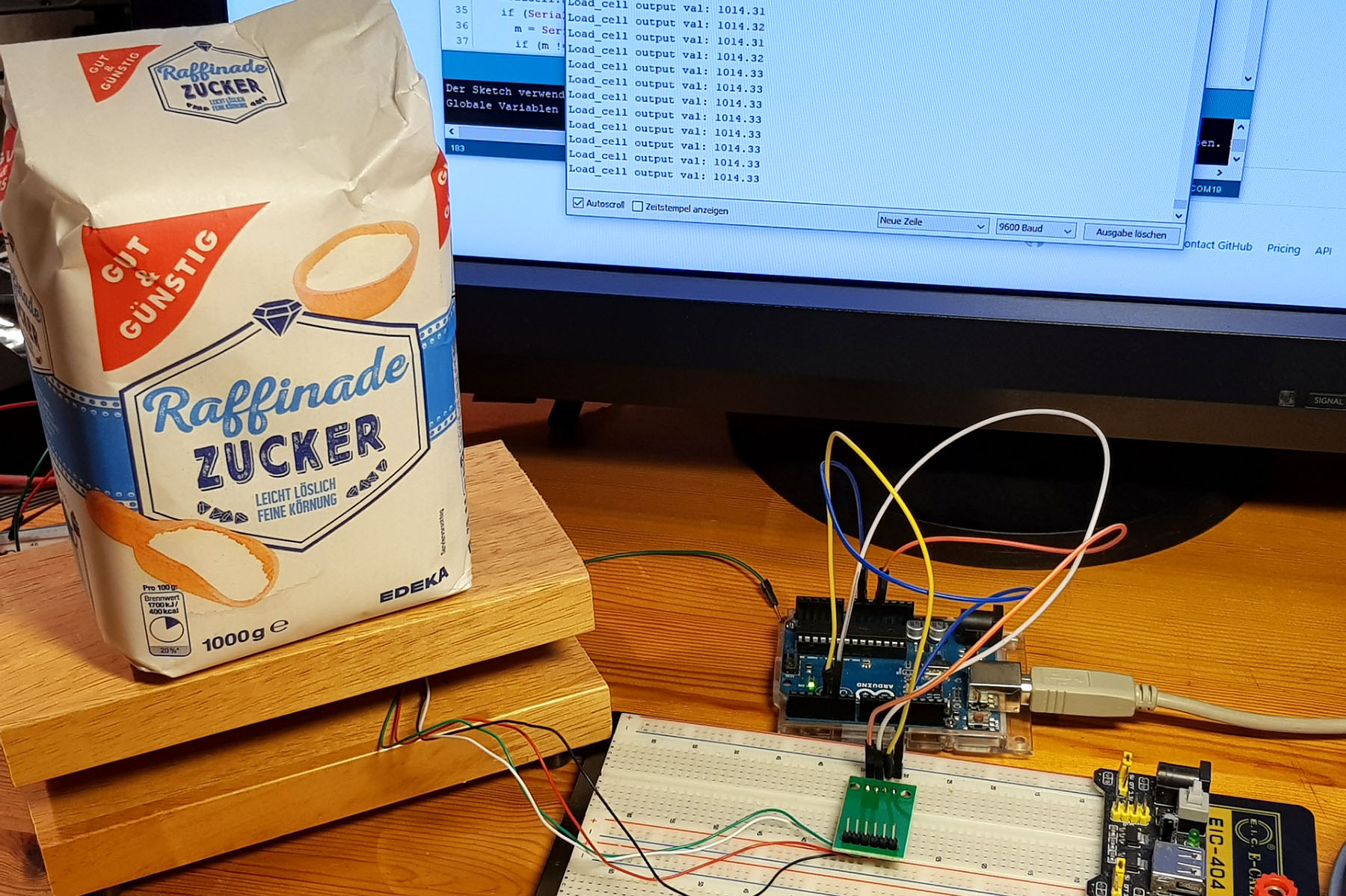
I then tested the HX711 based balance against my kitchen balance….
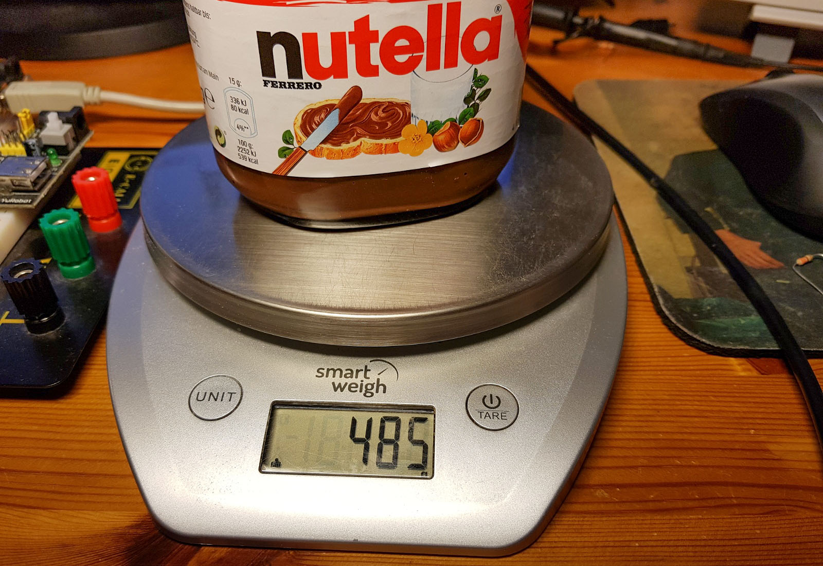
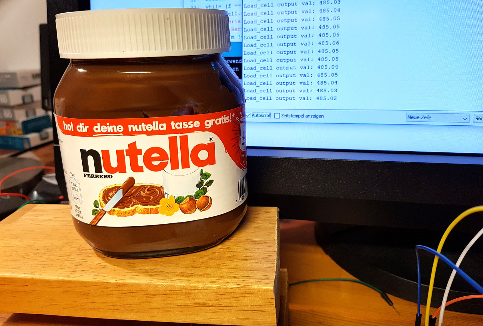
… and the results were right on the gram!
Output via an OLED display
To make the scale independent of the PC, you need an output medium. I have selected a small OLED display that requires only a few milliamperes of power. It is controlled via I2C using the libraries Adafruit GFX and Adafruit SSD1306. If you want to do the same, you can download the Github libraries from the links or install them via the library manager of the Arduino IDE. I do not go into the details here because that would go beyond the scope. In addition, you might want to use completely different displays or seven-segment displays.
A few notes on the following sketch. To display the weight, the function dtostrf(in, min_width, digits_after_decimal, out) is used. It allows to create a string (out) from float or integer values (in). The parameter min_width is the minimum width and digits_after_decimal sets the number of digits after the decimal. Actually, dtostrf() would also process the weight variable directly. However, my detour via the conversion into an integer prevents the display from constantly swinging back and forth between “0” and “-0” after a tare.
Tare measurements are requested via interrupts at pin 2. The interrupt is triggered by a button. When the button is pressed, the variable taraRequest turns true and thus a tare measurement is initiated in the main loop. During tare measurement, the balance outputs “Wait” on the display.
The rest of the sketch should be reasonably self-explanatory (of course, everyone claims that for their code…). If you have questions, ask!
#include <Wire.h>
#include <HX711_ADC.h>
#include <Adafruit_GFX.h>
#include <Adafruit_SSD1306.h>

#define OLED_RESET -1 // we don't have a reset, but the constructor expects it
#define SCREEN_WIDTH 128 // OLED display width, in pixels
#define SCREEN_HEIGHT 32

Adafruit_SSD1306 display(SCREEN_WIDTH, SCREEN_HEIGHT, &Wire, OLED_RESET);
HX711_ADC LoadCell(4, 5);

byte interruptPin=2;
volatile bool taraRequest = false;

void setup()   {
  pinMode(interruptPin, INPUT);
  attachInterrupt(digitalPinToInterrupt(interruptPin), taraEvent, RISING);
  display.begin(SSD1306_SWITCHCAPVCC, 0x3C);  // initialize with the I2C addr 0x3C (for the 128x64)
  display.clearDisplay();
  display.setTextSize(4);
  display.setTextColor(WHITE);
  display.setCursor(10,4);
  display.println("Wait");
  display.display();
  LoadCell.begin();
  LoadCell.start(2000);
  LoadCell.setCalFactor(883.24);
}


void loop() {
  float weightAsFloat = 0.0;
  static unsigned long t = 0;

  LoadCell.update();

  if (millis() > t + 250) {
    weightAsFloat = LoadCell.getData();
    displayWeight(weightAsFloat);
    t = millis();
  }
  if(taraRequest){
    doTara();
    taraRequest = false;
  }
}

void displayWeight(float weight){
  char weightAsString[6] = {0}; // sign (-) + 4 digits + Null character = 6
  dtostrf(weight,5,0,weightAsString);
  display.clearDisplay();
  display.setCursor(0,4);
  display.println(weightAsString);
  display.display();
}

void doTara(){
  LoadCell.tareNoDelay();
  display.clearDisplay();
  display.setCursor(10,4);
  display.println("Wait");
  display.display();
  while(LoadCell.getTareStatus()== false){
    LoadCell.update();
    delay(50);
  }
}

// IRAM_ATTR void taraEvent(){ for ESP32 / ESP8266
void taraEvent(){
  taraRequest = true;
}

The next evolutionary step: The scale goes to sleep
Then I wanted the scale and its components to go into standby mode when there is no change in weight or a new tare measurement being requested for some time. Since the Arduino UNO still consumes a lot of power in sleep mode (see my penultimate post about Sleep Modes), I used the bare ATmega328P here. I have described here how to program the ATmega328P with the Arduino IDE. The circuit for this is as follows:

In the sketch for this variant, I introduced the variable lastWeightAsFloat that stores the value of the last measurement. This value is compared to the current result. As long as the last and the current weight differ (difference < 1 g), the balance is obviously busy. And during that time the variable tLastChange is repeatedly updated to millis . The same happens during tare measurement. Once per main loop tLastChange is being compared with millis . If the difference exceeds 120,000 (= 2 min), the balance is sent to sleep. First the display is switched off, then the HX711 module and finally the ATmega328P is put into deep sleep mode.
An interrupt awakens the ATmega328P. Since the button for tare measurement triggers an interrupt, it also acts as awake-up function.
#include <Wire.h>
#include <HX711_ADC.h>
#include <Adafruit_GFX.h>
#include <Adafruit_SSD1306.h>
#include <avr/sleep.h>

#define OLED_RESET -1 // we don't have a reset, but the constructor expects it
#define SCREEN_WIDTH 128 // OLED display width, in pixels
#define SCREEN_HEIGHT 32

Adafruit_SSD1306 display(SCREEN_WIDTH, SCREEN_HEIGHT, &Wire, OLED_RESET);
HX711_ADC LoadCell(4, 5);

int interruptPin = 2;   // tara and wake-up pin
int powerOnPin = 6;
volatile bool taraRequest = false;
float weightAsFloat = 0.0; // current weight (as float)
float lastWeightAsFloat = 9999.0;  // former weight
unsigned long t = 0;    // system time of last weight measurement
unsigned long tLastChange = 0;  // system time of last change of weight

void setup()   {
  pinMode(interruptPin, INPUT);
  pinMode(powerOnPin, OUTPUT);
  digitalWrite(powerOnPin, HIGH);
  initBalance();
  attachInterrupt(digitalPinToInterrupt(interruptPin), taraEvent, RISING);
}

void loop() {
  LoadCell.update();
  /* In one loop a) measurement is done or b) a tara or c) the balance will be send to sleep
  or d) nothing happens */
  if (millis() > (t + 250)) {
    weightAsFloat = LoadCell.getData();
    displayWeight(weightAsFloat);
    if(abs(weightAsFloat-lastWeightAsFloat) >=1){
      tLastChange = millis();
      lastWeightAsFloat = weightAsFloat;
    }
    t = millis();
  }

  if(taraRequest){
    doTara();
    taraRequest = false;
  }

  if(millis() > (tLastChange + 120000)){ // after 2 min of no weight change or tara the balance shall fall asleep
    sleepAndWakeUp();
  }
}

void initBalance(){
  taraRequest = false;
  display.begin(SSD1306_SWITCHCAPVCC, 0x3C);  // initialize with the I2C addr 0x3C (for the 128x64)
  display.clearDisplay();
  display.setTextSize(4);
  display.setTextColor(WHITE);
  display.setCursor(10,4);
  display.println("Wait");
  display.display();
  LoadCell.begin();
  LoadCell.start(2000);
  LoadCell.setCalFactor(883.24);
  weightAsFloat = 0.0;
  lastWeightAsFloat = 9999.0;
  t = 0;
}

void displayWeight(float weight){
  char weightAsString[6] = {0};
  dtostrf(weight,5,0,weightAsString);
  display.clearDisplay();
  display.setCursor(0,4);
  display.println(weightAsString);
  display.display();
}

void doTara(){    // tara
  LoadCell.tareNoDelay();
  display.clearDisplay();
  display.setCursor(10,4);
  display.println("Wait");
  display.display();
  while(LoadCell.getTareStatus()== false){
    LoadCell.update();
    delay(50);
  }
  tLastChange = millis();
}

void taraEvent(){
  taraRequest = true;
}

void sleepAndWakeUp(){
  LoadCell.powerDown();            // switch off HX711
  display.ssd1306_command(SSD1306_DISPLAYOFF);
  set_sleep_mode(SLEEP_MODE_PWR_DOWN);  // deep sleep mode
  cli();
  sleep_enable();
  sleep_bod_disable(); // disable brown-out detector
  sei();
  sleep_cpu();
  /* ATmega328P sleeps */
  sleep_disable();
  LoadCell.powerUp();            // switch on HX711
  display.ssd1306_command(SSD1306_DISPLAYON);
  initBalance();
}
With this setup, I have measured a power consumption of 139 microamperes in sleep mode. That’s 3.3 milliampere hours per day. So a battery should last for some time.
Turn off the balance completely
Then I thought about how to turn off the scale completely without installing an additional switch (because everyone can!). Strictly speaking, the question is how the scale can turn itself off.
I solved the task with a thyristor. A thyristor has some similarities with a transistor. It has three connections, namely the cathode, the anode and the gate. A small current pulse at the gate opens the connection from anode to cathode. Unlike the transistor, the thyristor remains conductive as long as the current does not fall below a certain threshold. The MCR100-6 I used has a typical threshold of 0.5 milliamperes. Since the power consumption in sleep mode is much lower, the thyristor locks. The thyristor is “ignited” when the tare button is pressed. This is what the circuit looks like:

But there was a problem: As long as the thyristor is open, the voltage at gate remains high. Since we have a connection to the tare function, the voltage at the interrupt pin remains also high (orange line). This means that the tare request no longer works. That’s why I’ve installed a diode that blocks the way in that direction.
You can use the previous sketch. Lines 122 to 125, i.e. the actions after the wake-up, are of course never executed and can be deleted accordingly.
When designing the power supply, it should be noted that about 0.8 volts fall off the thyristor. Accordingly, less voltage is available to the components. With 5 volt power supply, this is no problem for the components used here.
Acknowledgement
I would like to thank Olav Kallhovd for his great library. The libraries of Adafruit helped me control the display.
I owe the scales on the post picture to Gerhard Gellinger on Pixabay. I have used the Arduino in the background several times. It comes from Seven_au on Pixabay.
Hi i made a beehive scale . When my esp32 going on deep sleep when wake up cannot understand the weight which on it . I save the last weight and inport when wake up . Any suggestion ? or can made work with your route ?
Hi,
this means you want to avoid tara during startup. This is no problem. You just need to pass a “false” after the stabilizing time in LoadCellStart, so like this:
bool _tare = false;
LoadCell.start(stabilizingtime, _tare);
But it might not work completely like you expect because the balances tend to shift over time. One reason is temperature changes, the other is slow deformation over time. Just try, good luck!
I am building a node mcu based weight scale but if my node mcu gets off the next time I switch on the weight on the scale is tared I wanted the actual weight to be displayed what changes should I do in the cone as to not tare it to zero everytime I switch on?
That’s easy to change. In the example sketches you find:
LoadCell.start(stabilizingtime, _tare);
Just change _tare from true to false and the initial tare will be off.