About the post
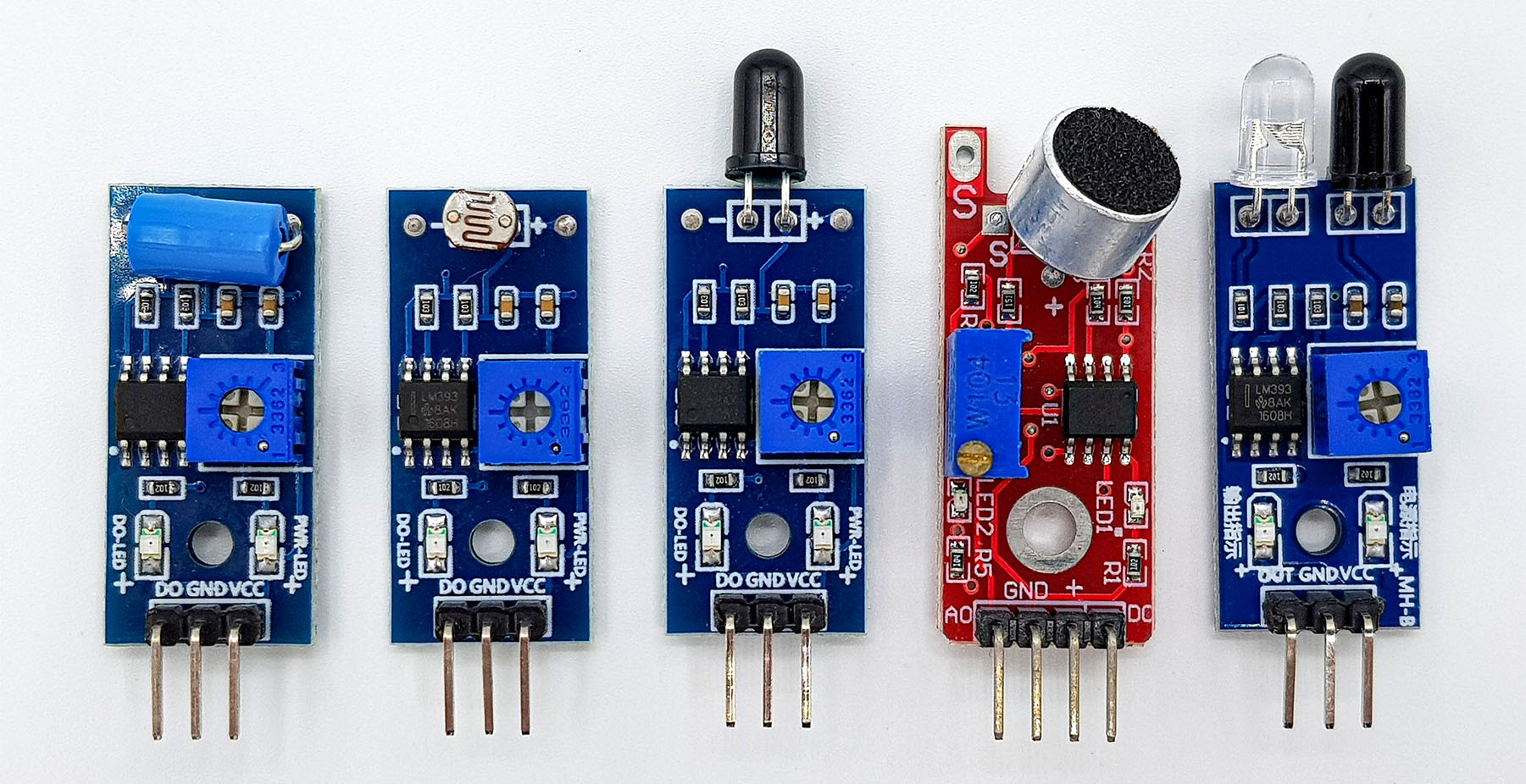
What do the sensor modules shown above have in common? The title of the article already reveals it: an LM393. In addition, all modules have a digital output, although the underlying sensors are analog. And finally, all sensors have a potentiometer that can be used to set the analog limit at which the digital output switches. In this article I would like to explain how this works and how you can use analog sensors digitally with an LM393.
Why digital instead of analog?
Imagine reading an analog signal and an action should be taken at a certain limit. For example, you measure the brightness of a light barrier via an LDR (photo resistor). If a certain value is exceeded, an alarm shall be triggered. You could of course read the analog signal with the analogRead function. However, this has some drawbacks:- You must read out the signals permanently so that no event is lost to you. This, in turn, can be problematic if there are other tasks to be done in between.
- AnalogRead is a comparatively slow function. About 100 µs are needed for this using the Arduino UNO. A digitalRead is almost fifty times faster and a direct read out of the Port Input Register PINxis even about three hundred and fifty times faster.
- If you receive the digital signal via an interrupt pin, you can also send the microcontroller to sleep in between (see my post about Sleep Modes). This would not be possible using the analogRead function.
Features of the LM393
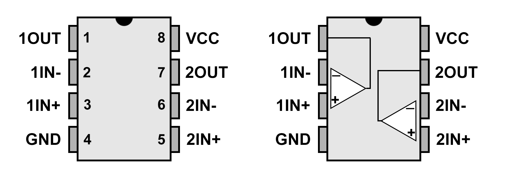
The LM393 has two independent comparators. The comparators each have two inputs (IN- and IN+) and one output (OUT). As the name suggests, the comparator compares something, namely the voltages at IN and IN+. At OUT there’s a transistor which state depends on the ratio of voltages:
- IN- voltage is greater than IN+ → OUT is closed against GND
- IN- voltage is less than IN+ → OUT is open against GND (Open Collector)
If you attach a pull-up resistor with the voltage VPU to OUT, the polarity changes between 0 and VPU. With this, you have your digital signal:
- IN- is less than IN+ → VOUT = VPU
- IN- is greater than IN+ → VOUT = 0 V
Electrical properties of the LM393
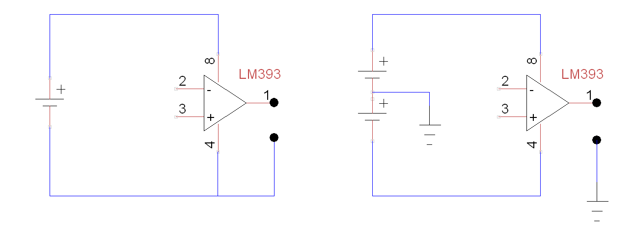
With single power supply of the LM393, the supply voltage can be 2 to 36 volts, with double power supply it should be 1 to 18 volts:
If OUT is open agains GND, the LM393 serves as a current sink. The maximum current should not exceed 16 milliamperes. So you can attach an LED to it, but nothing more.
The LM393 consumes approx. 0.4 mA. Further information can be found in the data sheet.
Where can I get the LM393?
The LM393 is a component that is available in virtually all (electronic) online shops. At Conrad, Reichelt and Co you get it for 20 to 30 cents, but you have to pay the shipping fees. With ebay and Amazon it is sometimes cheaper overall, but you should check where the shops are located. From China, it usually takes a few weeks.
The LM393 is available in different designs, e.g. DIP or SMD, and for different temperature ranges. This information is encoded in the full part designation, e.g. LM393AN, LM393ST, etc. In the data sheet you will find what the abbreviations mean.
Basic circuit of the LM393

Normally, the LM393 is used to compare a signal voltage VIN with a reference voltage Vref. Most of the time, you will find examples where VRef is IN- and VIN is IN+. But that doesn’t really matter. The reference voltage is usually provided by a voltage divider or a potentiometer. Between IN+ and VOUT you put a 1 MOhm resistor (R2). R3 is the pull-up resistor that pulls up VOUT when OUT is closed against GND. You can omit the resistors R1 and R4 if you attach a high-impedance potentiometer or voltage divider to IN- and IN+.
A circuit to get to know the LM393
The following circuit is intended to showcase how the LM393 works. An Arduino measures the voltages VREF,VIN and VOUT for us.
- The voltage divider R1 / R2 delivers (ideally) 2.5 volts. This is our reference voltage.
- The signal voltage VIN is variable and is supplied by a potentiometer.
- When OUT is open against GND, the LED1 starts to light up. Note the polarity – the LM393 acts as a current sink.
- The voltage VIN is measured at A1, VRef on A0 and VOUT on A2

If you take the above-mentioned resistance values, then the switching point for the LED should be approximately in the middle position of the potentiometer. With the following sketch you can follow VIN, VRef and VOUT:
const int refPin = A0;
const int vInPin = A1;
const int vOutPin = A2;
float vRef, vIn, vOut;

void setup() {
  Serial.begin(9600);
}

void loop() {
  vRef = analogRead(refPin)*5.0/1024;
  vIn = analogRead(vInPin)*5.0/1024;
  vOut = analogRead(vOutPin)*5.0/1024;
  Serial.print("VRef = ");
  Serial.print(vRef);
  Serial.print("  |  VIn = ");
  Serial.print(vIn);
  Serial.print("  |  VOut = ");
  Serial.println(vOut);
  delay(500);
}
This is what the result on the serial monitor might look like when you vary the voltage with the potentiometer:
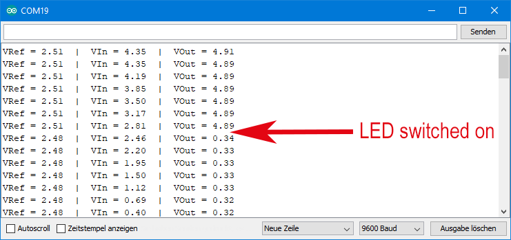
You can see nicely how VOUT “tilts” sharply when VIN slips under VRef.
Build a digital light sensor

Now we come to the actual topic, namely how you turn an analog sensor into a digital one. I want to show this with the example of a light sensor. Replace the resistor R1 of the voltage divider by an LDR and R2 with a suitable resistor, e.g. 33 kOhm. As the light intensity increases, the resistance of the LDR decreases and thus the signal voltage drops. The reference voltage is set with the potentiometer.
You no longer need the lines to the analogue inputs of the Arduino UNO. In addition, remove the LED and connect it to the Arduino Pin 13 instead. You connect OUT of the LM393 to the Arduino Pin 2. This is what the circuit looks like:

With the following small sketch you can check the circuit:
byte sensorPin=2;
byte ledPin=13;

void setup() {
  pinMode(ledPin, OUTPUT);
  pinMode(sensorPin, INPUT);
}

void loop() {
  while(!digitalRead(sensorPin)){
    digitalWrite(ledPin, HIGH);
  }
  digitalWrite(ledPin,LOW);
}
Turn the potentiometer until the LED is switched off. If you then cover the LDR with your hand, you’ll see that the LED lights up.
Using Interrupts
As already mentioned at the beginning of this article, the advantages of a digital sensor are only really used with interrupts.
Imagine you control a light barrier with the circuit above. This means that you may only have a very short “dark event”. In between, however, the microcontroller shall do other things, e.g. read out another sensor. Or, for some reason, you’ve added delays to your main loop. If you are unlucky, you will miss the triggering of the light barrier.
Here is the solution:
int interruptPin=2;
int ledPin=13;
volatile bool dark;

void setup() {
  pinMode(ledPin, OUTPUT);
  pinMode(interruptPin, INPUT);
  attachInterrupt(digitalPinToInterrupt(interruptPin), darkISR, FALLING);
  dark = false;
}

void loop() {
  if(dark){
    digitalWrite(ledPin, HIGH);
    delay(1000);
    digitalWrite(ledPin, LOW);
    dark = false;
    attachInterrupt(digitalPinToInterrupt(interruptPin), darkISR, FALLING);
  }
}

void darkISR(){
  dark = true;
  detachInterrupt(digitalPinToInterrupt(interruptPin));
}
Here, the “dark event” triggers an interrupt. The interrupt service routine darkISR sets the variable dark to true. And it turns off the interrupts on the interrupt pin so that no more interrupts are triggered before or while the actions are processed.
In the main program loop, the state of the variable dark is then queried in a relaxed manner at a given time. If dark is true, the LED on pin 13 lights up for one second. After that, dark is set to false and the interrupts on the interrupt pin are switched on again. The system is armed again, so to speak.
This way you can do other things in the main loop because you will not lose the information that an interrupt has been triggered.
If you haven’t been so familiar with interrupts since, maybe read this article on the Arduino pages.
Digitize other sensors
You should now be able to digitize other analog sensors. With most sensors, it’s even a bit easier than with the LDR, as they directly provide a voltage signal. This allows you to attach it directly to one of the comparator inputs. If necessary, you will still have a resistor in between. A potentiometer is attached to the other input and that’s it.
Dear Sirs
Do you have a LM393 or LM339 circuit for Heidenhain sine/cos to 5v TTL conversion?
I woulsd be most grateful.
Thank you Paul ABS Measurement CC south africa
Hello,
are you aware of this document:
https://www.heidenhain.com/fileadmin/pdf/en/01_Products/Prospekte/PR_Interfaces_ID1078628_en.pdf
Apart from this, I don’t have information.
Regards, Wolfgang
Dear W.Ewald,
Excellent tutorial.
I was trying to explain to a student why he should not buy arduino modules for sensors if he does not have has budget restrictions, but should choose a LM393 that would solve most of the lab needs.
Our world has evolved a lot faster with object oriented programming mind sets, but often forget to study fundamentals.
I have seen great solutions online, but also very complex solutions that a simple transistor with two resistor and maybe a capacitor would do it faster, less energy and more reliable.
Modules are great to buy to save time, and for less soldering work, specially for the less skilled makers (but a protoboard solves that too). Thank you for sharing your knowledge, great site.
Danke! ich schätze es (from Brazil)
Thank you so much for this feedback. It is very motivating for me. And great to see that people so far away from Germany read it. Greetings to Brazil and stay healthy!