About this post
In this post I’m going to look at remote shutters (also called remote triggers). It all started with a simple reader’s question about whether a Bluetooth module like the HC-05 or HC-06 could be used to simulate commercially available remote shutters for smartphone cameras. This could be used to build a camera trap, for example. My first thought was that this would be easy. In hindsight, this is a good example of supposedly simple projects spinning out of control as you go from one challenge to the next.
The whole thing then got so big that I ended up splitting the post into two parts. This first part deals with the topics of
- Remote shutters – ready-made solutions
- Hacking of a remote shutter and control with the Arduino (Uno)
- Solving problems in long-term operation
- Control without Arduino, for example only with a motion sensor
In the next post, I’ll show you how to use Bluetooth modules like the HC-05 or HC-06 as remote triggers, giving you much more flexibility.
Remote shutters – ready-made solutions
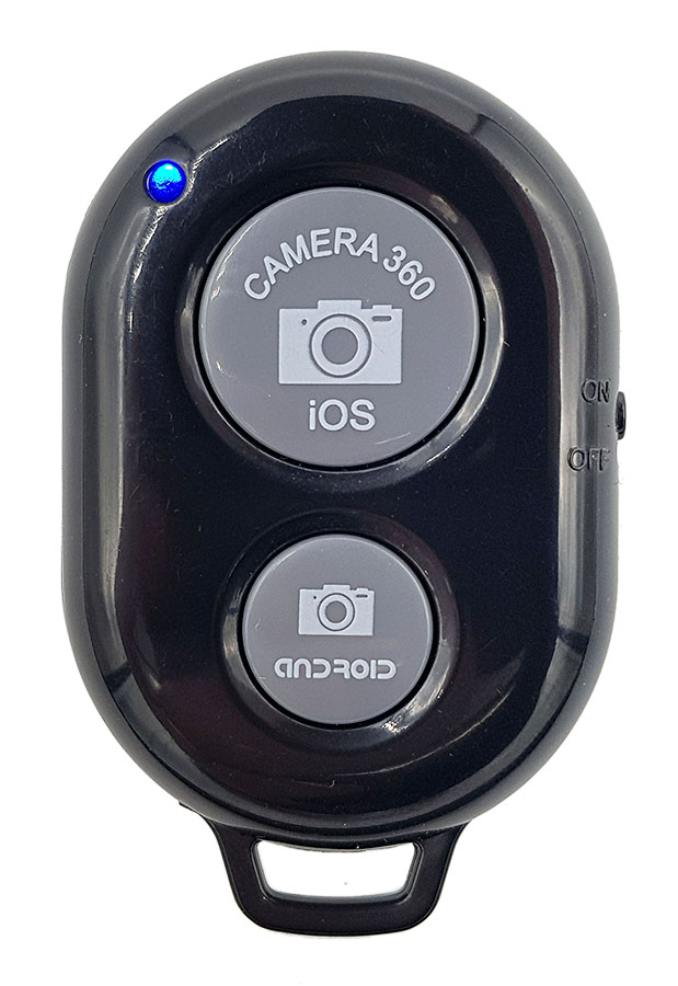
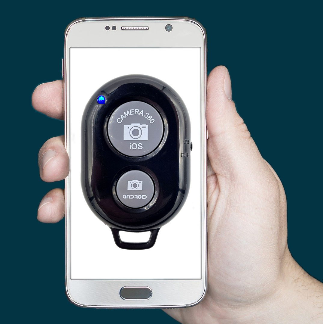
Bluetooth remote shutters for smartphones are available for a few euros at Amazon, for example. I bought the model pictured on the right. The function is very simple. You need to turn on the remote trigger and pair it with your smartphone. Bluetooth is probably turned on by most of you in these Corona times anyway. Then you start your smartphone camera app. The remote trigger has two buttons. Although one is labeled iOS and the other Android, both work with my Android smartphone:
- big button:
- short press: a photo is taken
- small button:
- short press: a blue border appears around the trigger button on the smartphone, each further press triggers a photo
- for both buttons:
- long press: triggers continuous shooting after pressing for approx. 1 second (can be changed in the smartphone settings)
Bluetooth protocols and profiles
As I had to learn myself, there are various Bluetooth profiles that build on the general Bluetooth specification or other protocols. I do not want to go into this further. What is relevant is that not every Bluetooth device or module can communicate with every other. The remote shutter communicates according to the HID (Human Interface Device) profile. And this does not work with the firmware present on the Bluetooth modules. You can change the firmware (instructions here), but then you would still need to familiarize yourself with the HID profile. I myself am still looking for an understandable introduction to the subject.
Conclusion: A (simple) emulation of the remote shutter by a Bluetooth module is not possible.
Hacking the remote shutter and switching from the outside
The next idea was to bridge the button of the remote release in a suitable way so that it can be switched from the outside. I am not the first to come up with this idea. The method has been described here before, but I found a simpler way, with one less solder connection and no transistor. The latter, however, also has a disadvantage that I still have to come to. So, I’m showing both ways. The preparation of the remote shutter is the same for both paths.
Preparing the remote shutter
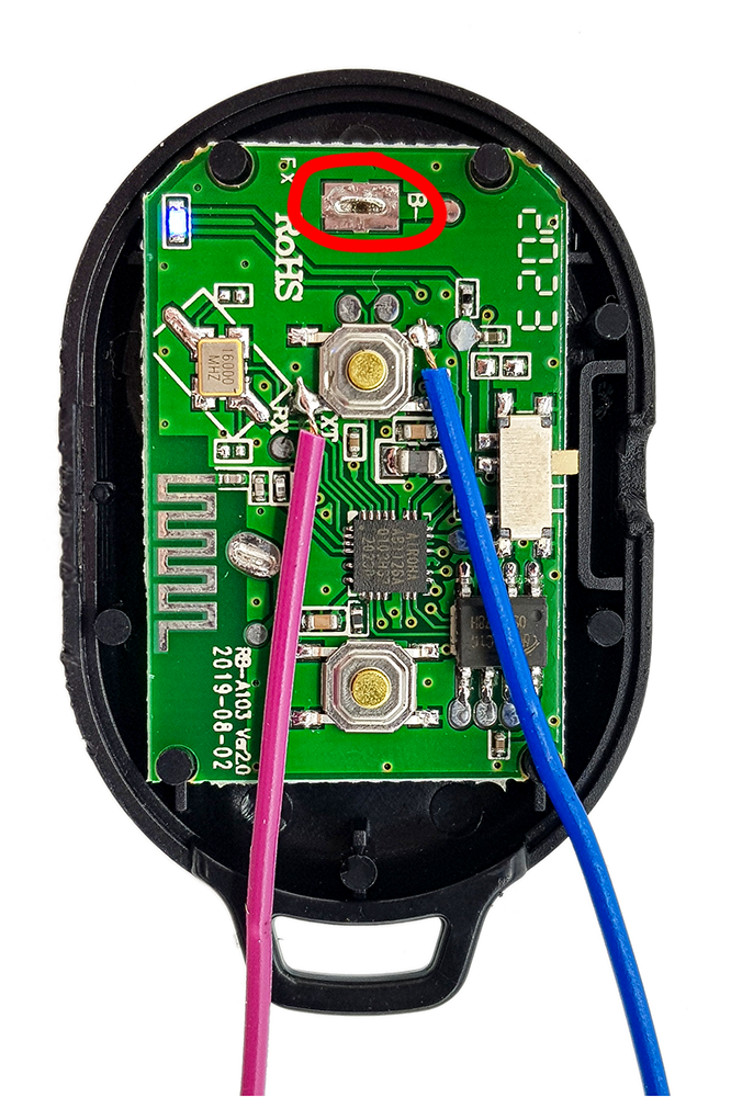
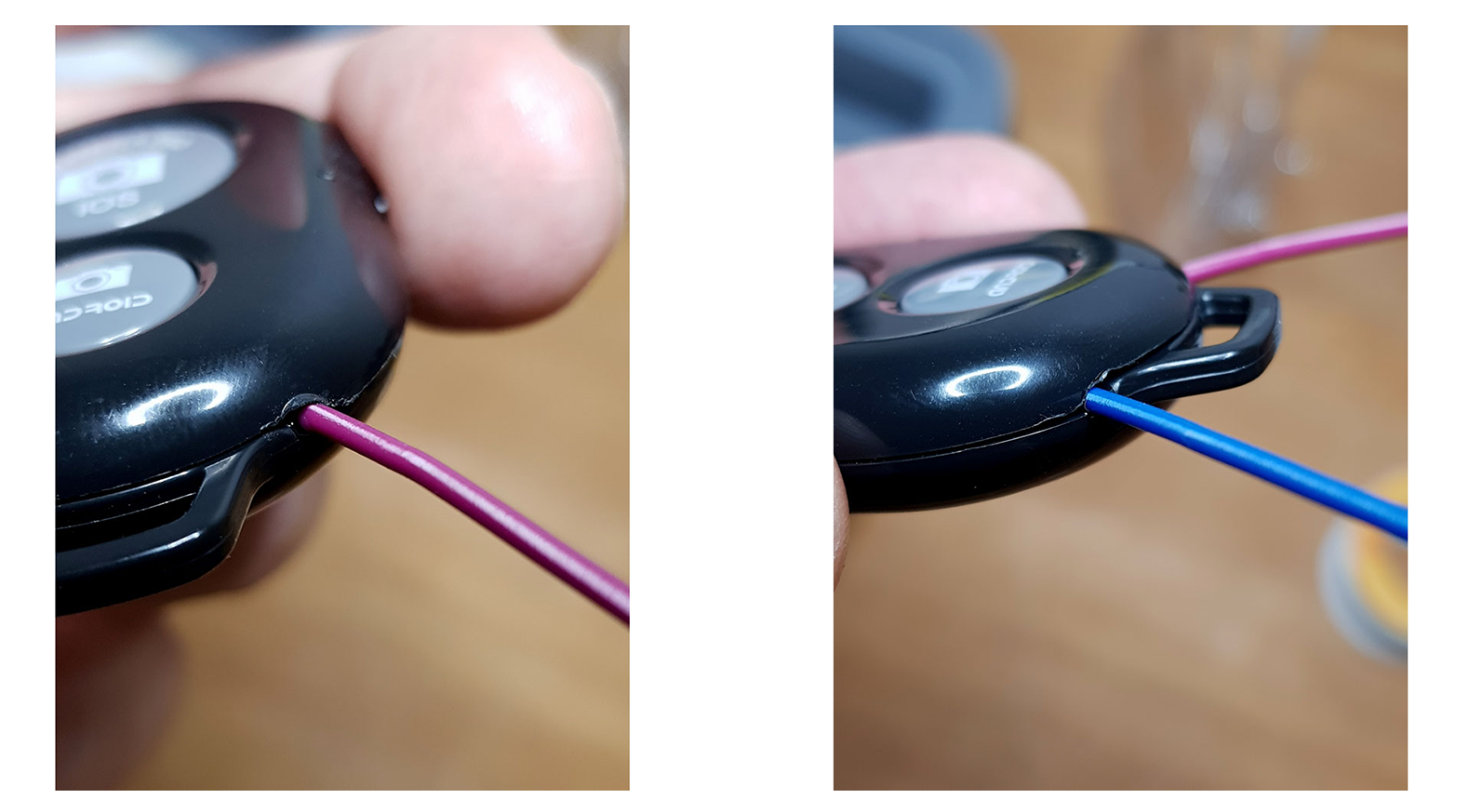
First, you carefully (!) open the case. A sharp knife with a sturdy blade is suitable for this purpose. Choose which button you want to use. With a wire or similar you can check which are the relevant two of the four contacts. Bridge them on a trial basis and observe when the LED lights up. Then you solder your connection cables. I took jumper cables for this, which I cut off on one side. The contact on which the blue cable is soldered is also GND of the remote shutter. Note that the position of GND at the pushbutton under the large button (picture right) is reversed from the pushbutton under the small button (picture below). Another GND connector is highlighted in red in the right image. If you are not sure, measure the resistance between the contacts and this GND contact.
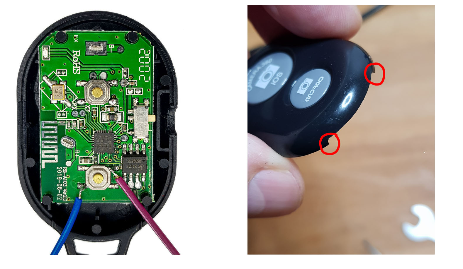
You can use the board without a housing, but you have to make sure that the battery has fixed contact, or you use an external power supply (3.7 volts). Alternatively, do as I did and continue to use the housing. File a recess in the top cover or use a Dremel tool to do this. I did this in the places outlined in red, as shown above. As a strain relief, I attached the cables to the lower cover with some superglue.
Option 1: without transistor
Wiring
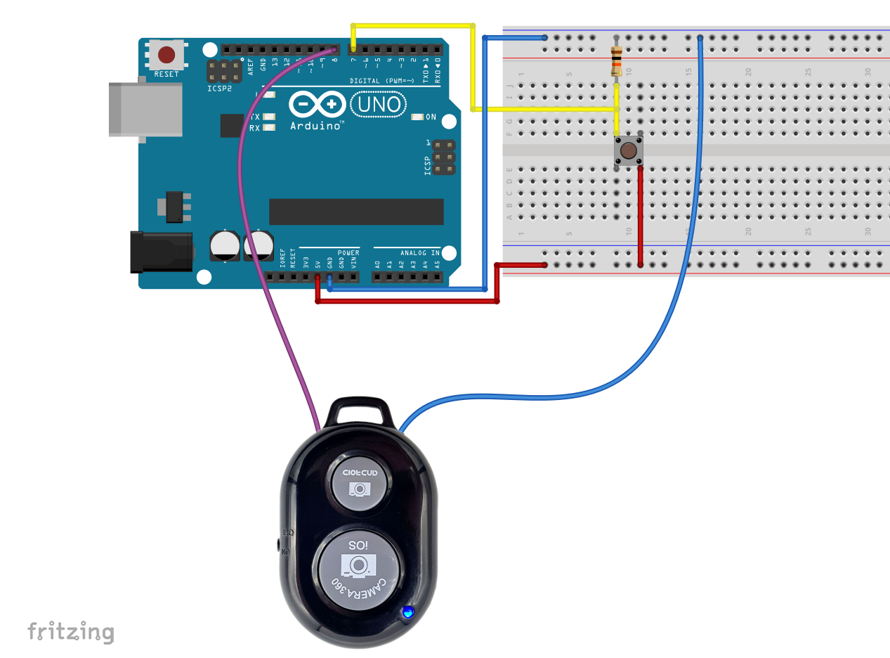
Connect the GND cable (blue for me) to GND of the Arduino. The other (violet) cable is connected to an I/O pin. Then you need an event to activate the remote shutter. I have chosen a button, which in itself is of course pointless. You can come up with something exciting. How about a motion, distance, vibration or gesture sensor?
Sketch
You switch the trigger by briefly changing the pin mode of the I/O pin connected to the purple cable from INPUT to OUTPUT and back again. In INPUT mode, the pull-down resistor of the I/O pin is active. In OUTPUT mode the I/O pin is open and the current can flow in unhindered. This simulates the pressing of the pushbutton.
const int tasterPin=7;
const int shutterPin=8;

void setup() {
  pinMode(tasterPin, INPUT);
  pinMode(shutterPin, INPUT);
  digitalWrite(tasterPin,LOW);
  digitalWrite(shutterPin,LOW);
}

void loop() {
  if(digitalRead(tasterPin)){
    pinMode(shutterPin, OUTPUT);
    delay(20);
    pinMode(shutterPin, INPUT);
  }
}
You should test how long the delay needs to be. I didn’t try for long. The remote shutter releases the photo when the button is released. So if the delay is too long, the photo is taken accordingly late. Or you might trigger continuous shooting.
Disadvantage of this method: If you disconnect the Arduino from the power supply, it is as if the remote trigger is permanently pressed. So, you have to turn off the remote trigger beforehand.
Option 2: with transistor
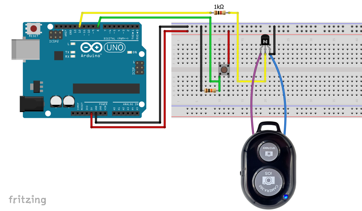
In this version, you connect the soldered wires to the emitter and the collector of an NPN transistor, e.g. a BC547. Then you can trigger the remote shutter with a HIGH signal on the base pin of the transistor. You need to wire the right way around and provide a common ground.
The button is again used as an event sensor for viewing. Here’s what the sketch looks like:
const int tasterPin=8;
const int shutterPin=12;

void setup() {
  pinMode(tasterPin, INPUT);
  pinMode(shutterPin, OUTPUT);
}

void loop() {
  if(digitalRead(tasterPin)){
    digitalWrite(shutterPin, HIGH);
    delay(10);
    digitalWrite(shutterPin, LOW);
  }
}
Problems in long-term operation and their solution
Issue 1: The display turns off and the camera app stops
The smartphone’s camera eventually goes off after some time and the display goes dark. That usually makes sense. Unfortunately, the remote shutter only triggers a photo when the camera is activated. This is bad for long-term use.
With the Tasker app, you can leave the camera and display on. This app costs €3.59, but I find it pretty awesome and use it for many other purposes. I will come back to Tasker in the next article.
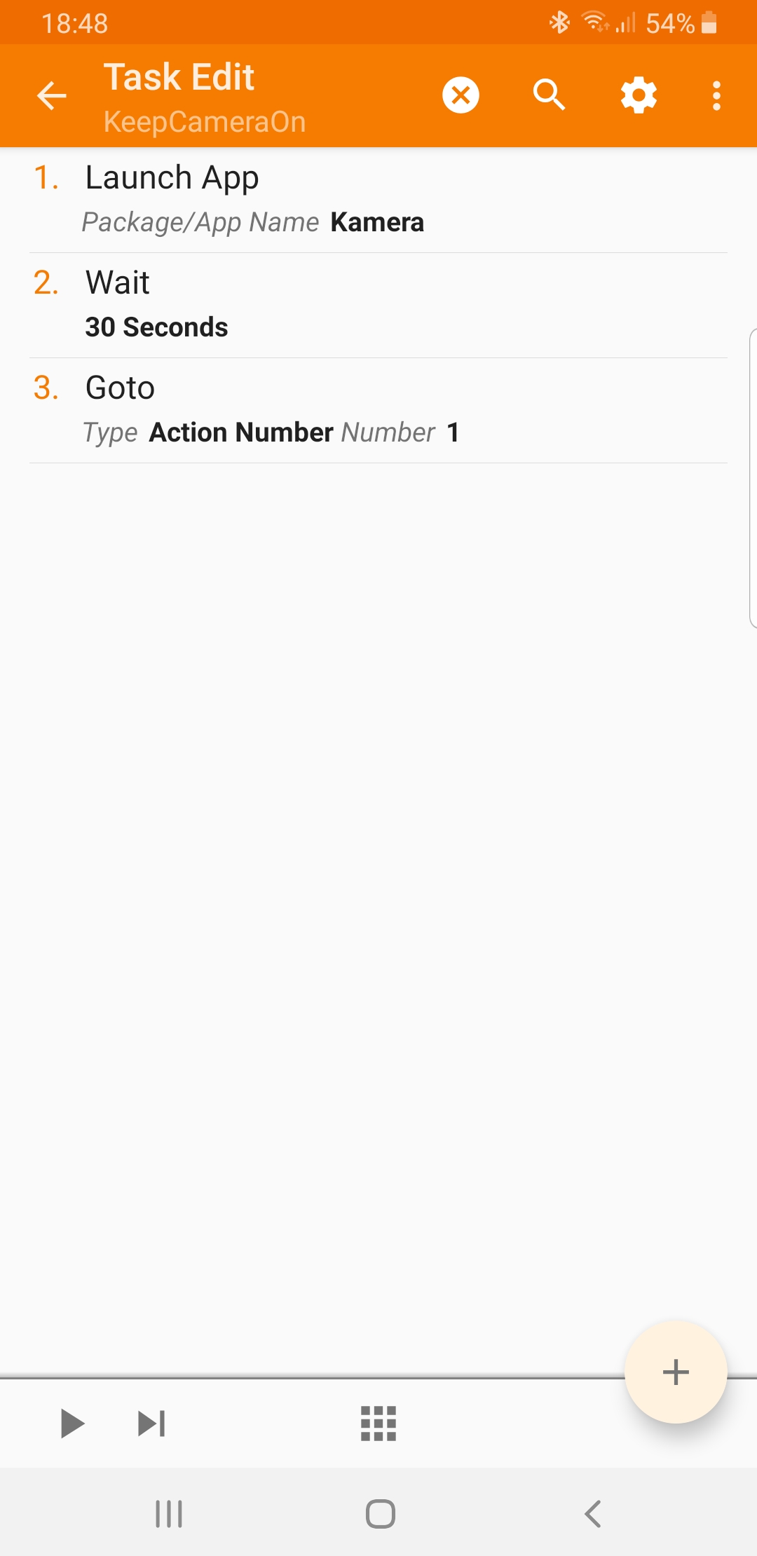
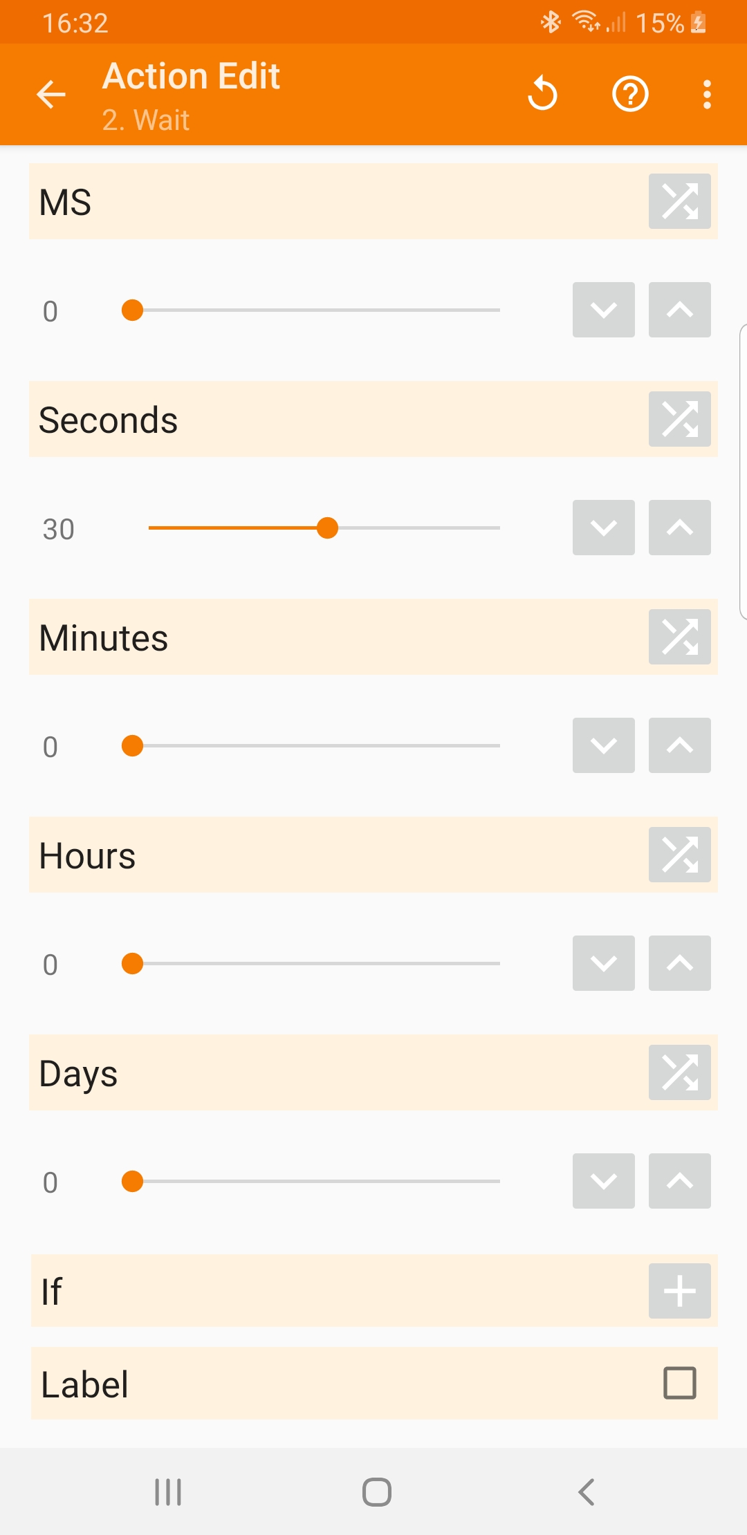
The quick guide is: Create a new task that simply turns on the camera every 30 seconds. Depending on your settings in your smartphone, you can extend this even longer. On the right you can see a screenshot. In the appendix I explain in detail how you create this task.
The battery consumption is of course immense when the display is permanently switched on. For applications that take several hours, the smartphone must be connected to the charger.
Issue 2: Bluetooth connection is lost
After a few minutes, the Bluetooth connection is lost. You can track this in the Bluetooth settings of your smartphone. I suspect that the remote shutter is going in a sleep mode. However, if you press the remote shutter once or trigger it via the Arduino, it re-connects. This takes a few seconds. If you press again, a photo will be triggered as usual.
The next sketch (transistor variant) triggers a photo every 15 minutes. You can transfer the principle to the variant without a transistor.
const int shutterPin=12;
unsigned long startingTime = 0;

void setup() {
  pinMode(shutterPin, OUTPUT);
  triggerShutter();
  startingTime = millis();
}

void loop() {
  if((millis() - startingTime) > 900000){

    triggerShutter();
    delay(5000);
    triggerShutter();

    startingTime = millis();
  }
  else{
    delay(1000);
  }
}

void triggerShutter(){
  digitalWrite(shutterPin, HIGH);
  delay(20);
  digitalWrite(shutterPin, LOW);
}
Unfortunately, the whole thing is sluggish, because of the delay(5000);. The construction of a camera trap is therefore only possible to a limited extent.
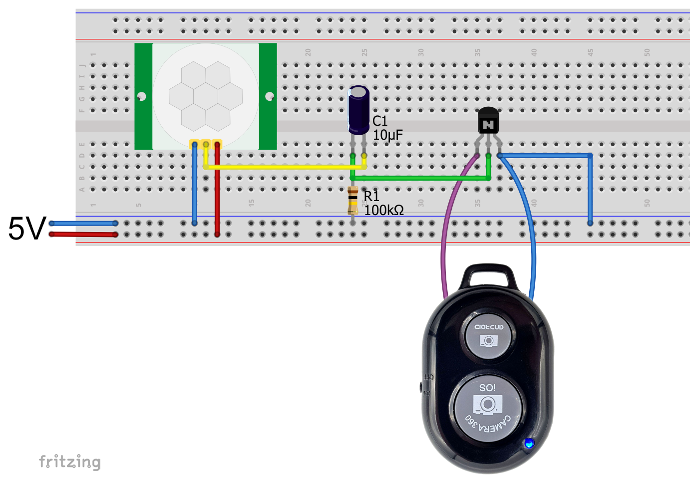
Option 3: Sensor with digital output
You can also switch the transistor directly with a sensor if it has a digital output. As an example, I take the motion sensor HC-SR501.
The disadvantage, however, is that the remote shutter triggers with the falling edge of the HC-SR501 signal, i.e. in the best case about 2 seconds after motion detection. But a remedy is in sight!

If you have a sensor with LOW-active signal, you can easily invert the signal with another transistor.

Option 3A: Shorten the sensor signal
How can a signal be shortened? The answer is: with a high pass (also known as CR link or RC link). In its simplest version, this consists only of a capacitor and a resistor. An input voltage UE charges the capacitor. The current only flows until the capacitor is charged. At the output there is correspondingly only a short voltage speak UA.

The width of the signal at the output depends on the size of the capacitor and the resistance. The signal was shortened to fractions of a second with 10 µF and 100 kOhm. The smartphone now reacts quickly to the detected motion.
The disadvantage remains that the Bluetooth connection is interrupted after a few minutes. To take photos, you must trigger at least twice. With a NE555 you could certainly build a solution that provides a double signal. But that would go too far here.
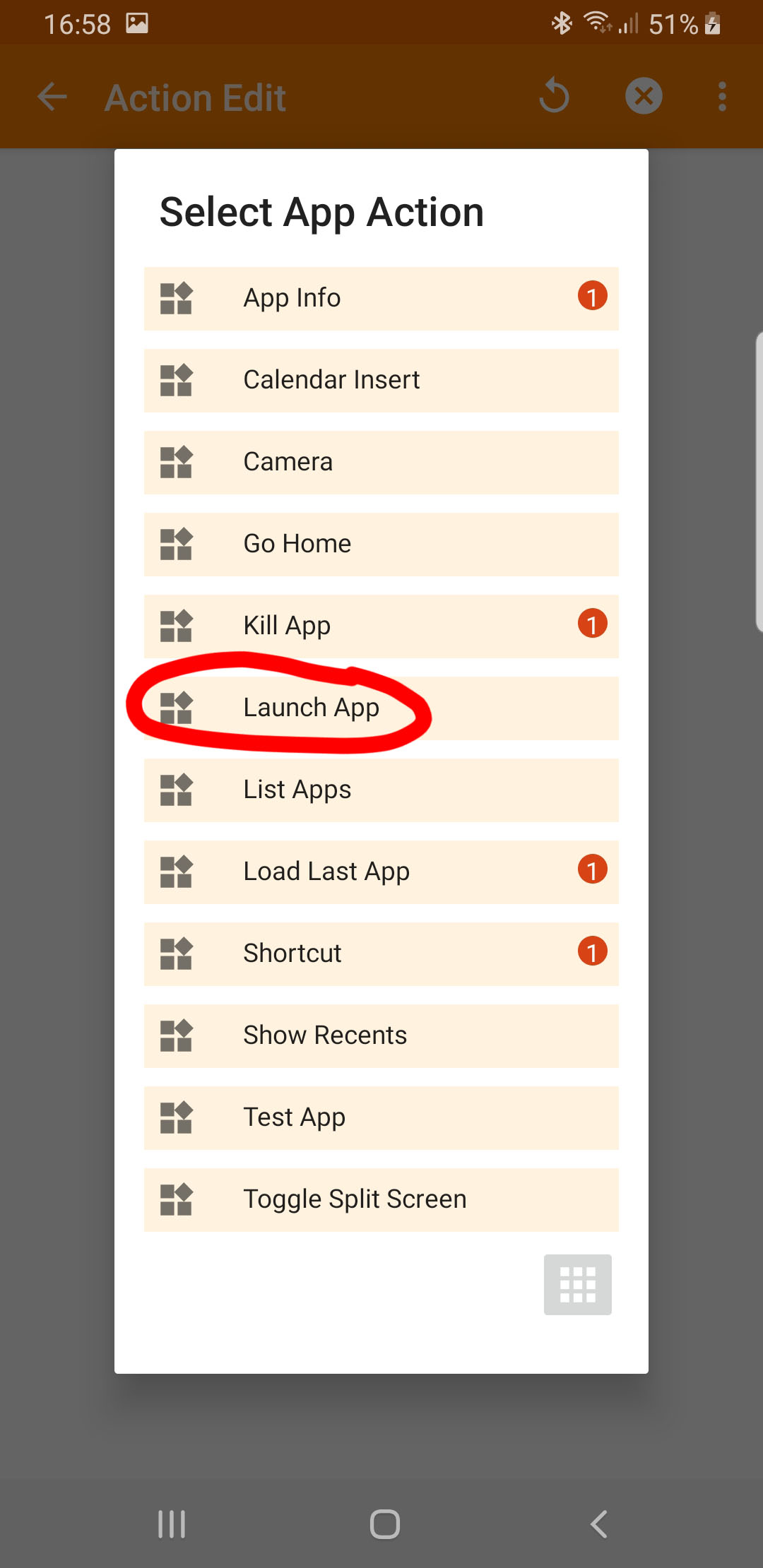
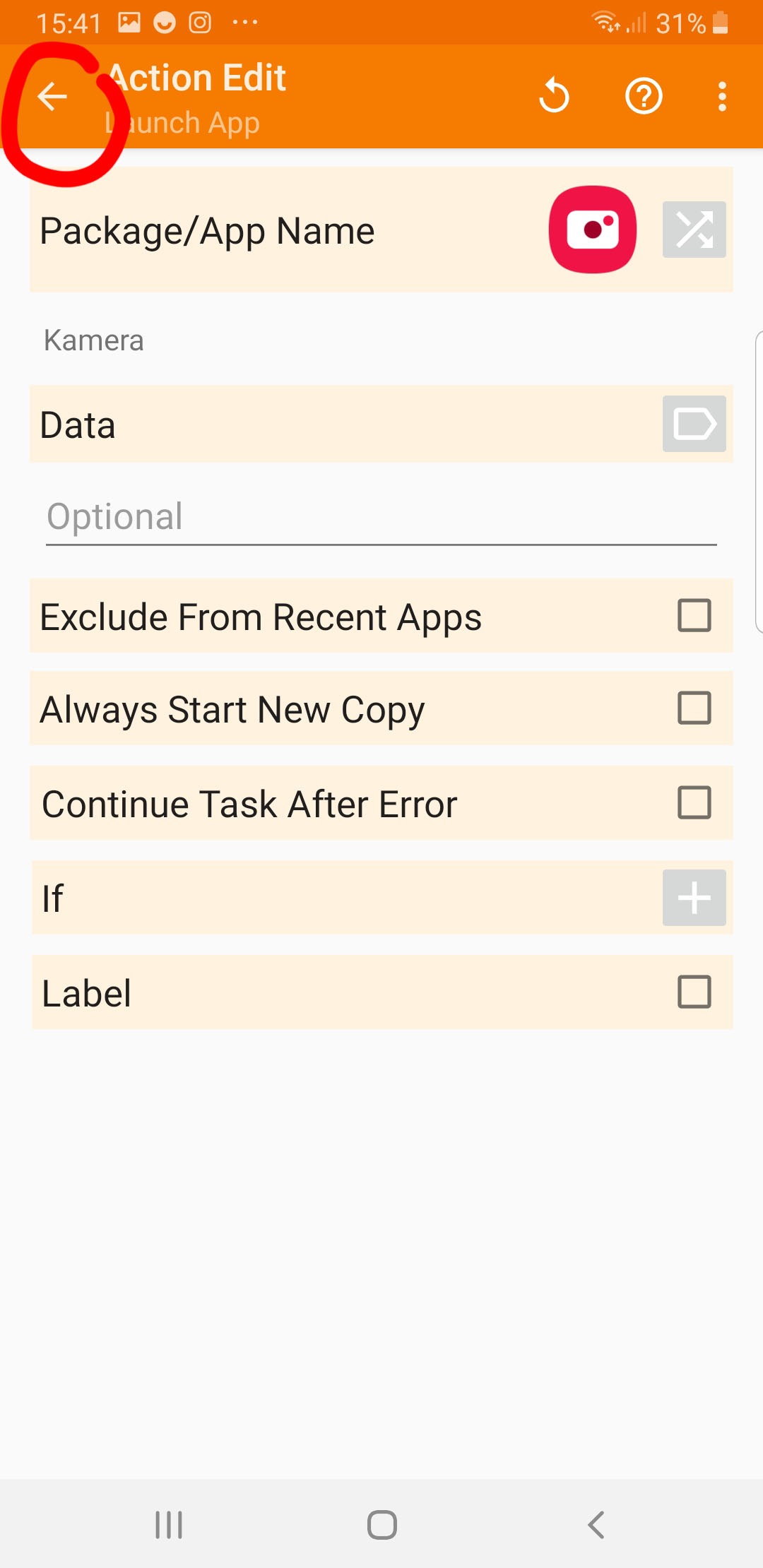
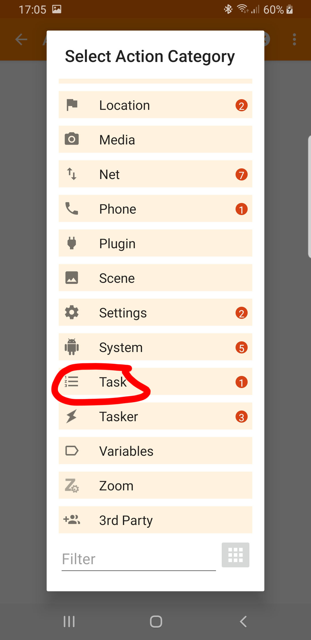
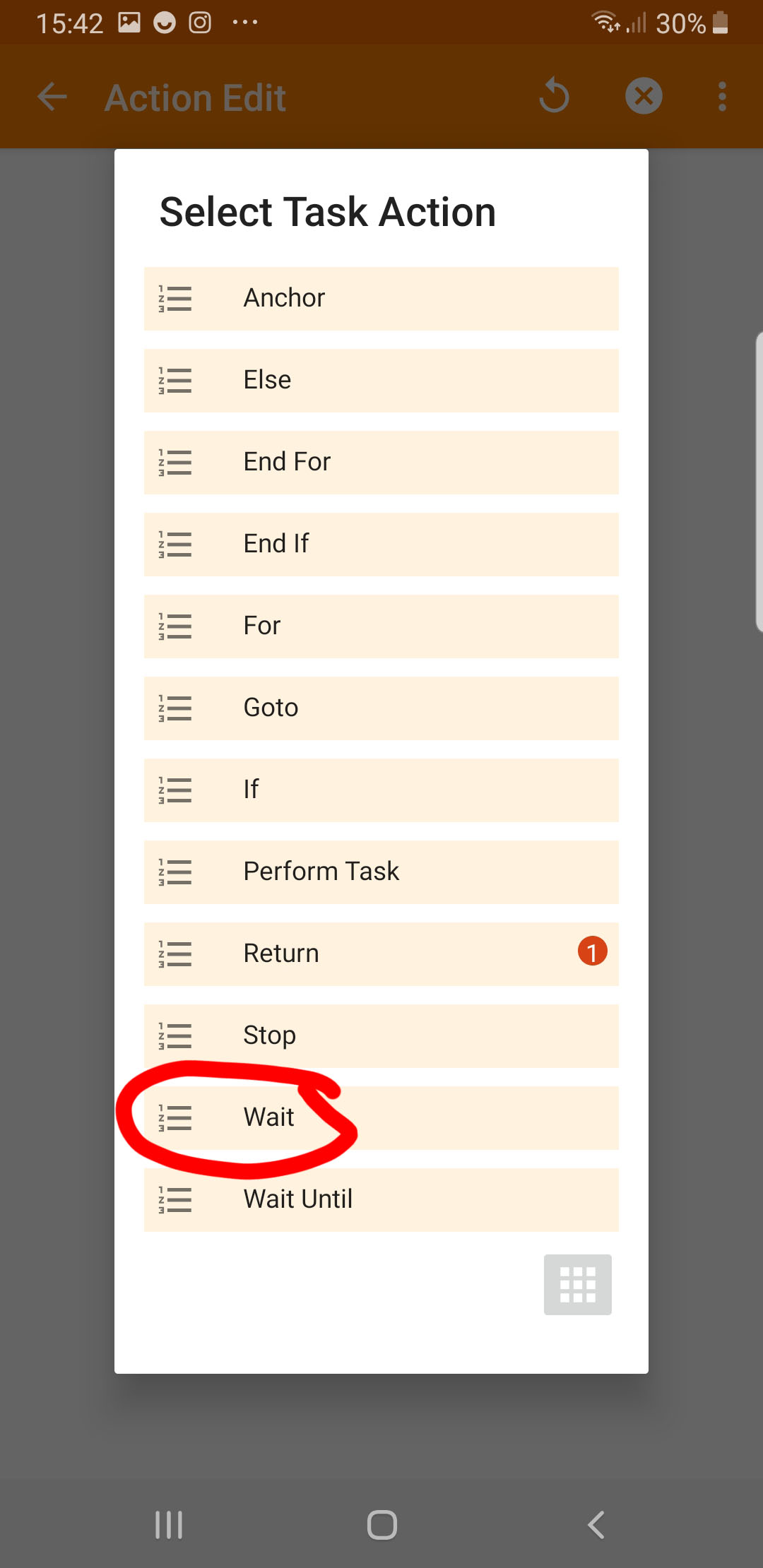
Appendix: Create the “Camera Always-on-Task”
Finally, a step-by-step guide on how to create the “camera-always-on-task” with the Tasker app. A task (“in Tasker language”) is just a sequence of commands that run within the Tasker environment. Basically, like a batch file.


Acknowledgement
I owe the basis of the post image to Pete Linforth on Pixabay.