About this post
If you search Google for the terms “current sensor” and “Arduino”, you will come across the ACS712 very often. After reporting on the current sensor modules INA219, INA226 and the self-built current sensor, I would now like to introduce this very popular module.
At currents below one ampere the ACS712 in combination with the A/D converter of the Arduino UNO reaches its limits. I’ll take a special look at this and show you how to get better results. Finally, I’ll explain how you can use the ACS712 as a power sensor.
Properties of the ACS712 (module)
The measuring principle of the ACS712
The ACS712 or the ACS712 module measures currents based on the Hall effect. In an earlier post, I had reported on Hall sensors. These are used to detect magnetic fields or to build contactless switches using magnets. In the ACS712, on the other hand, the current to be measured generates a magnetic field, which is converted into a voltage, which you can then pick up at the pin “Out”.
Due to its measuring principle, the ACS712 influences the current to be measured even less than the shunt-based modules from my previous articles. The resistance is only 1.2 milliohms. However, the sensitivity is not particularly high, and the ACS712 requires considerably more power.
Depending on the wiring, the ACS712 IC delivers a voltage between 66 and 185 millivolts per ampere. Using the module, the wiring is fixed. Most modules I have in online shops have implemented the maximum sensitivity of 185 millivolts per ampere. But there are also others available. With the bare ACS712 IC you are free to choose the sensitivity. Another advantage of the bare IC is that you can control the filter function (pin 6 of the IC, see data sheet).
Technical data (module)
Here are the most important technical data:
- Power supply at VCC/GND: 4.5 – 5.5 V.
- Power consumption of the ACS712 IC: ~ 10 mA.
- Due to its LED, the current consumption of the module is slightly higher: about 12 mA.
- Sensitivity of the module: 185 mV / A.
- Alternatively, modules with a sensitivity of 100 or 66 mV/A are available.
- Linearity deviation: 1.5% (according to the data sheet).
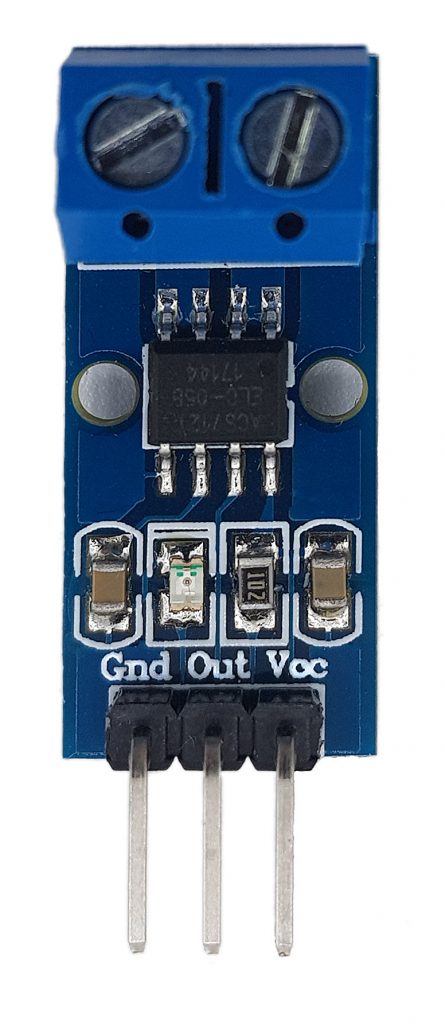
- 5 Inputs / Outputs:
- VCC/GND Power supply.
- OUT: Output voltage (signal).
- IN+ (top right) / IN- (top left): Input and output for the current to be measured.
- Voltage at OUT at 0 amps: VCC/2.
The signal voltage VOUT is thus, with a supply voltage VCC, dependent on the current to be measured I:
![\[ V_{OUT}\,[\text{mV}]=185\,[\text{mV/A}]\cdot I\,[\text{A}]+\frac{VCC\,[\text{mV}]}{2} \]](https://wolles-elektronikkiste.de/wp-content/ql-cache/quicklatex.com-67c352b3a2dc7581fa18c7791947778e_l3.png "Rendered by QuickLaTeX.com")
Solved for I:
![\[ I\, [\text{A}]=\frac{V_{OUT}-\frac{VCC}{2}}{185} \]](https://wolles-elektronikkiste.de/wp-content/ql-cache/quicklatex.com-879bbf50c5eb64414ab246ae30ad21e3_l3.png "Rendered by QuickLaTeX.com")
If you have a module with a different sensitivity, simply replace the 185 with 100 or 66.
The ACS712 “Quick and Dirty”
If you want to use the ACS712 with the Arduino, you can connect it as follows:
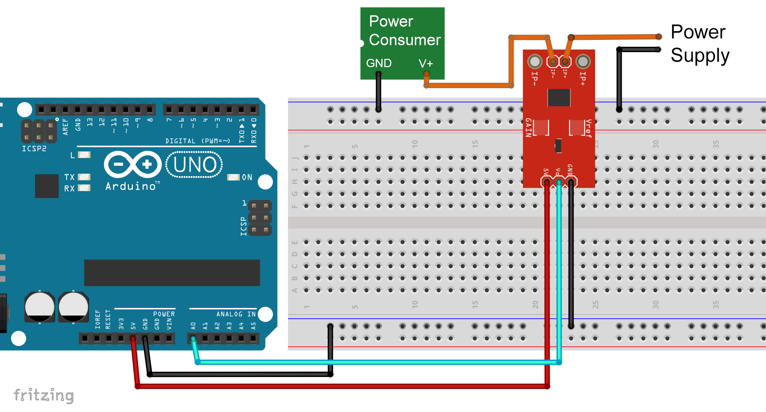
This is the high-side configuration, i.e. the ACS712 is placed on the V+ side of the consumer to be measured. You can also put the ACS712 behind the consumer on the GND side (low-side).
Then I first took care of the zero point, meaning the voltage at OUT (labeled Vo in the Fritzing schematic above) at zero amps of current flow. Theoretically, this is 2.5 volts, i.e. a analogRead(A0) should return 1024/2 = 512. In practice, you will probably measure somewhat less. Even under the low load of the ACS712, the voltage provided by the Arduino already drops by a few millivolts. Thus, also the zero value at OUT is somewhat lower. Thereby, the zero value at OUT is also somewhat lower. I have determined 510, but fluctuating by up to +/-3 units.
Since the Arduino has a reference voltage of 5 volts and its A/D converter has a resolution of 10 bits, the following applies to the voltage at pin A0:
![\[ V_{\text{A0}}[\text{V}]=analogRead(\text{A0})\cdot\frac{5}{1024} \]](https://wolles-elektronikkiste.de/wp-content/ql-cache/quicklatex.com-c7ef3d4b9bbf1301948a9e552040504e_l3.png "Rendered by QuickLaTeX.com")
Inserted into the equation for the current above, the following simple sketch results:
const int ACS712_Pin = A0;
const int zeroCurrentValue = 510;

void setup() {
  Serial.begin(9600);
  Serial.println("ACS712 - Basic sketch");
}

void loop() {
  int rawValue= analogRead(ACS712_Pin);
  float current = (rawValue - zeroCurrentValue)*5.0/1.024/0.185; // for modules with 185 mV/A
  Serial.print("Current [mA]: ");
  Serial.println(current);
  delay(2000);
}
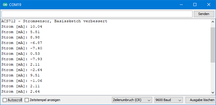
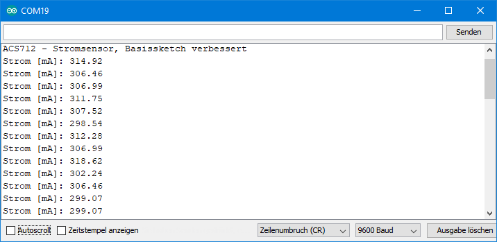
With this sketch, I typically got results like the following at zero amperes:

The level of noise would not be very satisfactory, even for measurements in the ampere range. However, the fluctuating results are not only the fault of the ACS712. What fluctuates here above all is the A/D converter of the Arduino UNO. Take a stabilized current source or simply an unloaded battery and measure the voltage via analogRead(). You will notice that the read values vary by +/-2 to 3 units. One unit is 5000/1024 = ~4.883 millivolts and that equals 4.883/0.185 = 26.39 milliamps.
Improvement 1: Averaging
It is obvious that noisy results can be improved by averaging. To do this, I first determined the zero value more precisely (510.8). Then I changed the sketch so that 50 measurement results are averaged:
const int ACS712_Pin = A0;
const float zeroCurrentValue = 510.8;
void setup() {
  Serial.begin(9600);
  Serial.println("ACS712 - current sensor, improved basic sketch");
}

void loop() {
  long rawValue = 0;
  for(int i=0; i<50; i++){
    rawValue += analogRead(ACS712_Pin);
  }
  float rawVoltage = rawValue/50.0;
  float current = (rawVoltage - zeroCurrentValue)*5.0/1.024/0.185; // for modules with 185 mV/A
  Serial.print("Current [mA]: ");
  Serial.println(current);
  delay(2000);
}
The result looks much better. Fluctuations were in the range +/-10 milliampere:
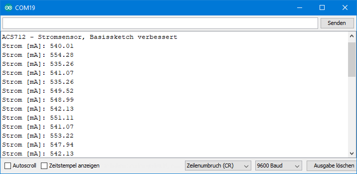
As the current increases, the variation remains at about +/- 10 milliamperes, i.e. the noise component decreases. Here are the results for a current that my multimeter and my lab power supply have shown me as a constant 305 milliampere:
And here are the results for 536 milliamperes:
The measured values obtained in this way were, on average, slightly higher than the actual current. The factor of 185 mV/A would have to be corrected slightly upwards accordingly. But because of the fluctuations, I didn’t want to make a science out of it anymore.
Improvement 2: A better A/D converter
In the next step, I used an ADS1115 instead of the Arduino A/D converter. I have described the ADS1115 and my associated library here. That is why I do not go into all the details in this article.
The ADS1115 is an A/D converter with a resolution of 16 bits, it has 4 channels (A0 – A3) and an internal amplifier. Furthermore, it offers the possibility to measure voltage differences between the channels. You can take advantage of this by using a voltage divider to generate a reference voltage of 2.5 volts and then measuring the voltage difference between the reference (channel A1) and the OUT signal of the ACS712 (channel A0):
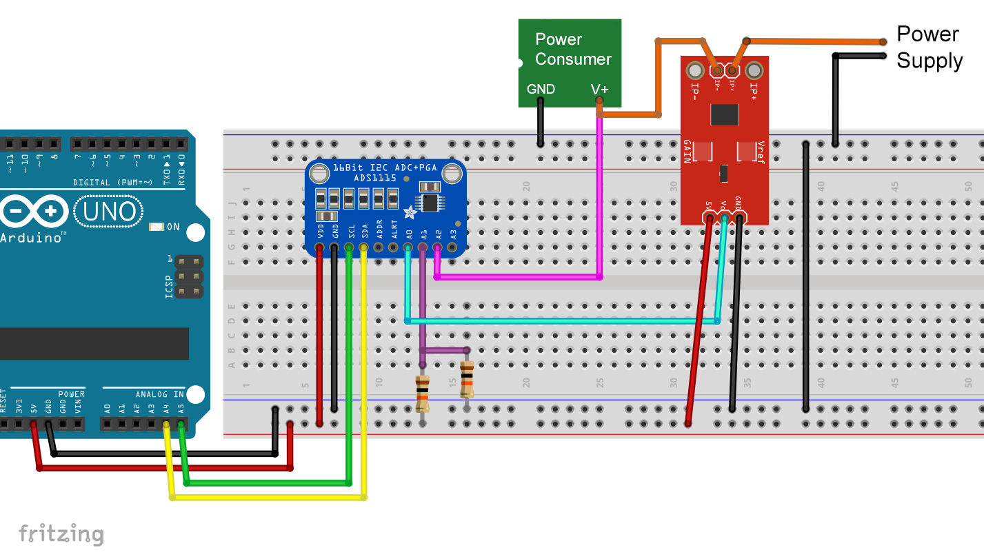
At zero ampere current flow, you start with a voltage difference of about zero volts. With small currents, you get low voltages that you can amplify with the ADS1115.
Note: You will see later why I connected the V+ of the consumer to A2. Wait, especially if your power supply for the consumer generates more than 5 volts! The voltage at the inputs A0 – A4 must not exceed the supply voltage of the ADS1115 by more than 0.3 volts. In this example, that would be 5.3 volts. If the supply voltage for the consumer is higher, you must install suitable voltage dividers to protect the inputs(i.e. here A2). Otherwise, you will destroy the ADS1115!
Checking the measured value fluctuations
For a first impression, I looked at the fluctuations at zero ampere. To do this, I used the following sketch:
#include<ADS1115_WE.h>
#include<Wire.h>
#define I2C_ADDRESS 0x48
const float zeroCurrentVoltage_mV = 0.0;

ADS1115_WE adc(I2C_ADDRESS);

void setup() {
  Wire.begin();
  Serial.begin(9600);
  if(!adc.init()){
    Serial.println("ADS1115 not connected!");
  }

  /* Set the voltage range of the ADC to adjust the gain
   * Please note that you must not apply more than VDD + 0.3V to the input pins!
   *
   * ADS1115_RANGE_6144  ->  +/- 6144 mV
   * ADS1115_RANGE_4096  ->  +/- 4096 mV
   * ADS1115_RANGE_2048  ->  +/- 2048 mV (default)
   * ADS1115_RANGE_1024  ->  +/- 1024 mV
   * ADS1115_RANGE_0512  ->  +/- 512 mV
   * ADS1115_RANGE_0256  ->  +/- 256 mV
   */
  adc.setVoltageRange_mV(ADS1115_RANGE_0256);

  /* Set the inputs to be compared
   *
   *  ADS1115_COMP_0_1    ->  compares 0 with 1 (default)
   *  ADS1115_COMP_0_3    ->  compares 0 with 3
   *  ADS1115_COMP_1_3    ->  compares 1 with 3
   *  ADS1115_COMP_2_3    ->  compares 2 with 3
   *  ADS1115_COMP_0_GND  ->  compares 0 with GND
   *  ADS1115_COMP_1_GND  ->  compares 1 with GND
   *  ADS1115_COMP_2_GND  ->  compares 2 with GND
   *  ADS1115_COMP_3_GND  ->  compares 3 with GND
   */
  adc.setCompareChannels(ADS1115_COMP_0_1);

  Serial.println("ACS712 - Nullstrommessung mit ADS1115");
  Serial.println();
}

void loop() {
  float voltage = 0.0;

  for(int i=0; i<10; i++){
    adc.startSingleMeasurement();
    while(adc.isBusy()){}
    voltage += adc.getResult_mV();
  }

  voltage /= 10;
  voltage -= zeroCurrentVoltage_mV;
  float current = voltage/0.185;
  Serial.print("ADC712-Spannung [mV]: ");
  Serial.print(voltage);
  Serial.print("  /  Strom [mA]: ");
  Serial.println(current);
  delay(2000);
}
A few comments on the sketch:
zeroCurrentVoltage_mVis the voltage between OUT and the reference voltage at zero ampere current. I first set the value to zero, ran the sketch, determined the actual value, and then used it accordingly (I determined 2.0 mV).setVoltageRange(ADS1115_RANGE_0256)sets the voltage range to +/- 256 mV. This corresponds to the maximum possible amplification of the ADS1115.setCompareChannels(ADS1115_COMP_0_1)specifies that the voltage difference between channels 0 and 1 is measured.getResult_mV()returns the result of the conversion directly in millivolts.- With an average of ten measurements, I was able to achieve an acceptable stability of the values.
Here is the result:

That doesn’t look so bad, does it? If we assume that the slope is actually 185 mV/A, the above sketch can already be used as is.
Improvement 3: Calibration
In the next step I looked at the dependence of the current on the voltage. For this I used different consumers, measured the current with my multimeter and determined the voltage with the sketch ACS712_am_ADS1115_Basis.ino. This is the result:
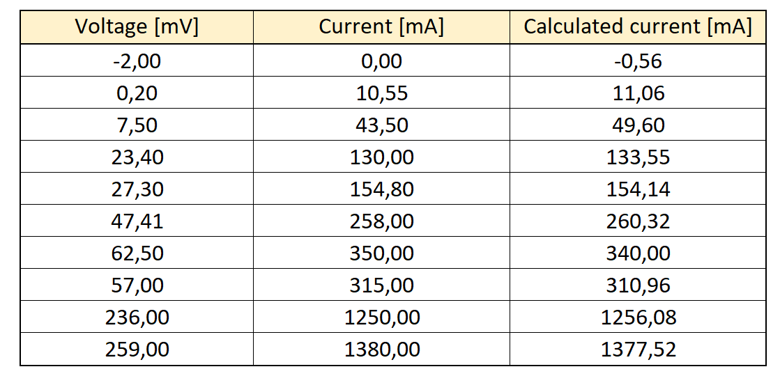
Here shown graphically with a regression line:
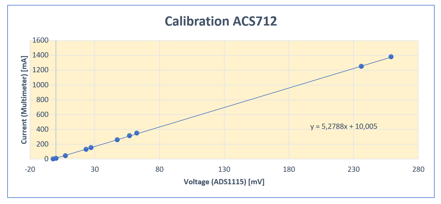
The measured values fitted well to a regression line. I then inserted the voltage values from Table 1 into the equation for the regression line. The results can be found in the right column of Table 1. They give an impression of how accurate the measurement is. More values would be needed for exact statistics, but it can be estimated that the deviation drops to less than 1 percent for currents above 1 ampere.
The slope of the regression line is 5,2788 mA/mV. This corresponds to 189.4 mV/A, which is slightly higher than the specified 185 mV/A, but not miles away.
Improvement 4: Power sensor function
If you follow the described path, you could now improve the last sketch by using the equation for the regression line. But you may also want to determine the power consumption. This is where the voltage measurement at V+ of the power consumer (bus voltage) comes into play. At this point I would like to emphasize again that the voltage at the inputs of the ADS1115 must not exceed the operating voltage of the ADS1115 by more than 0.3 volts. If V+ is greater, then use voltage dividers.
With the voltage at V+ and the current (bus current) you can calculate the power:
![\[ P_{Consumer}=U_{V_{+}}\,\cdot I_{Bus} \]](https://wolles-elektronikkiste.de/wp-content/ql-cache/quicklatex.com-5244141eb55ecb6ef218ece6bbea9453_l3.png "Rendered by QuickLaTeX.com")
And here’s the complete sketch:
#include<ADS1115_WE.h>
#include<Wire.h>
#define I2C_ADDRESS 0x48

ADS1115_WE adc(I2C_ADDRESS);

void setup() {
  Wire.begin();
  Serial.begin(9600);
  if(!adc.init()){
    Serial.println("ADS1115 not connected!");
  }

  /* Set the voltage range of the ADC to adjust the gain
   * Please note that you must not apply more than VDD + 0.3V to the input pins!
   *
   * ADS1115_RANGE_6144  ->  +/- 6144 mV
   * ADS1115_RANGE_4096  ->  +/- 4096 mV
   * ADS1115_RANGE_2048  ->  +/- 2048 mV (default)
   * ADS1115_RANGE_1024  ->  +/- 1024 mV
   * ADS1115_RANGE_0512  ->  +/- 512 mV
   * ADS1115_RANGE_0256  ->  +/- 256 mV
   */
  //adc.setVoltageRange_mV(ADS1115_RANGE_1024); //uncomment line / change parameter to change range

  /* Set the inputs to be compared
   *
   *  ADS1115_COMP_0_1    ->  compares 0 with 1 (default)
   *  ADS1115_COMP_0_3    ->  compares 0 with 3
   *  ADS1115_COMP_1_3    ->  compares 1 with 3
   *  ADS1115_COMP_2_3    ->  compares 2 with 3
   *  ADS1115_COMP_0_GND  ->  compares 0 with GND
   *  ADS1115_COMP_1_GND  ->  compares 1 with GND
   *  ADS1115_COMP_2_GND  ->  compares 2 with GND
   *  ADS1115_COMP_3_GND  ->  compares 3 with GND
   */
  //adc.setCompareChannels(ADS1115_COMP_0_1); // uncomment line / change parameter to change channels

  Serial.println("ACS712 - Current and power sensor sketch");
  Serial.println();
}

void loop() {
  float voltage = 0.0;

  adc.setCompareChannels(ADS1115_COMP_0_1); // Channel 0 vs. 1
  adc.setVoltageRange_mV(ADS1115_RANGE_0512); // Limit: 512 mV

  for(int i=0; i<10; i++){
    adc.startSingleMeasurement();
    while(adc.isBusy()){}
    voltage += adc.getResult_mV();
  }
  voltage /= 10;

  Serial.print("V Out          [mV]: ");
  Serial.println(voltage);

  float current_mA = voltage * 5.28 + 10; // experimentally determined
  Serial.print("Bus current   [mA]: ");
  Serial.println(current_mA);

  adc.setVoltageRange_mV(ADS1115_RANGE_6144); // Limit: 6144 mV
  adc.setCompareChannels(ADS1115_COMP_2_GND); // Channel 2 vs. GND
  adc.startSingleMeasurement();
  while(adc.isBusy()){}
  voltage = adc.getResult_V();
  Serial.print("Bus voltage    [V]: ");
  Serial.println(voltage);

  float power_mW = (voltage * current_mA);
  Serial.print("Power         [mW]: ");
  Serial.println(power_mW);

  Serial.println("-------------------------------");
  delay(2000);
}
Between the measurements of the ACS712 voltage and V+ voltage I change the range in the above sketch. I have chosen the range of +/-512 mV for the ACS712 voltage. Used in the equation for the regression line this results in a maximum current of approx. 2.7 amperes. If you need more, then increase the range accordingly.
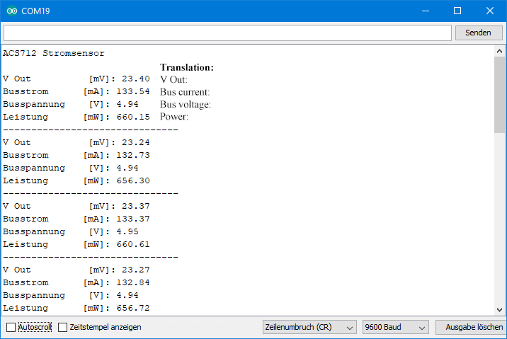
Here’s what the output looks like:
Acknowledgement
As usual, I used Pixabay again for parts of my post picture:
- The magnifying glass comes from the OpenClipart-Vectors
- The already frequently used electricity meter is taken from the free-photos section.