About this Post
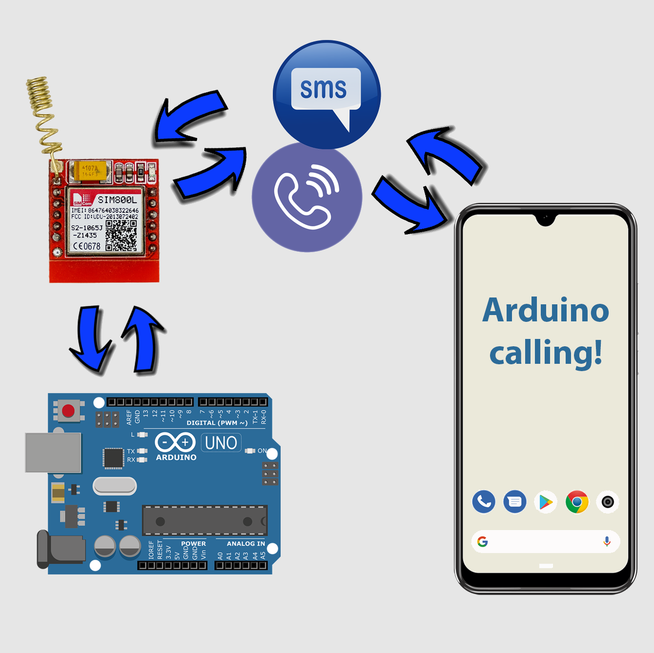
The SIM800L module allows you to build a mobile phone that you can control with your microcontroller. The range of functions is huge. Most of you are certainly primarily interested in SMS and telephony, for example for data transmission in areas without WiFi access. But the SIM800L offers many more functions, such as FTP, TCP/IP and HTTP applications, e-mail, or MMS. One could write a whole book about the SIM800L module.
In order not to make this post too long, I will focus on the following topics:
- Technical features of the SIM800L
- Wiring of the SIM800L module
- Communication via AT commands
- How to send SMS
- How to receive SMS
- Controlling microcontrollers via SMS
- Controlling microcontrollers via calls
- Restrict the access – whitelist
- Query and synchronize the time
- Programming the SIM800L module with a library
- Appendix: GSM location – an attempt
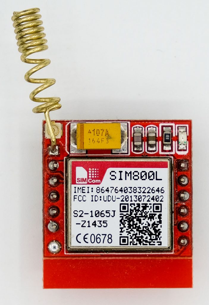
Technical characteristics
The SIM800L is a quad-band GSM / GRPS module. It covers the GSM850, EGSM900, DCS1800 and PCS1900 frequency bands. To use the SIM800L, you need a 2G micro-SIM card. Your microcontroller communicates with the SIM800L serially via RX/TX and AT commands.
The voltage range for the power supply is an unusual 3.4 to 4.4 volts. For this reason and because of current peaks of up to 2 amps, power supply via the microcontroller is not possible. Lithium-ion batteries are suitable, or you can use switching regulators such as the LM2596. For switching regulators, however, you still need a suitable power supply.
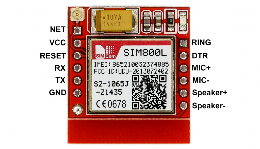
The SIM800L module has the following pins:
- Antenna connector (IPX U.FL, top left / unlabeled).
- NET: Antenna connector for spiral antennas.
- VCC: Power supply (3.4 – 4.4 Volt).
- RESET: active-low, you can leave it unconnected.
- RX/TX: serial ports, baud rate: 1200 – 115200 bps.
- GND: connect to GND of the power supply and GND of the microcontroller.
- RING: HIGH by default, briefly goes LOW when a call or SMS is received; useful for interrupt programming.
- DTR: controls sleep modes.
- MIC+/MIC-: Microphone connectors.
- Speaker+/-: here you can connect 8-ohm speakers directly and get a “full” 1.08 watts.
RX / TX voltage level
There are contradictory statements about the permissible voltage level of the serial interfaces of the SIM800L. Some say it can handle 5 volts, others see the limit at 3.3 volts. According to the data sheet, however, the maximum is 2.8 volts. You can also find there how to optimally connect 3.3 volt and 5 volt microcontrollers (from page 31). I only used a voltage divider in the RX line of the module and did well with it.
Antennas for the SIM800L module
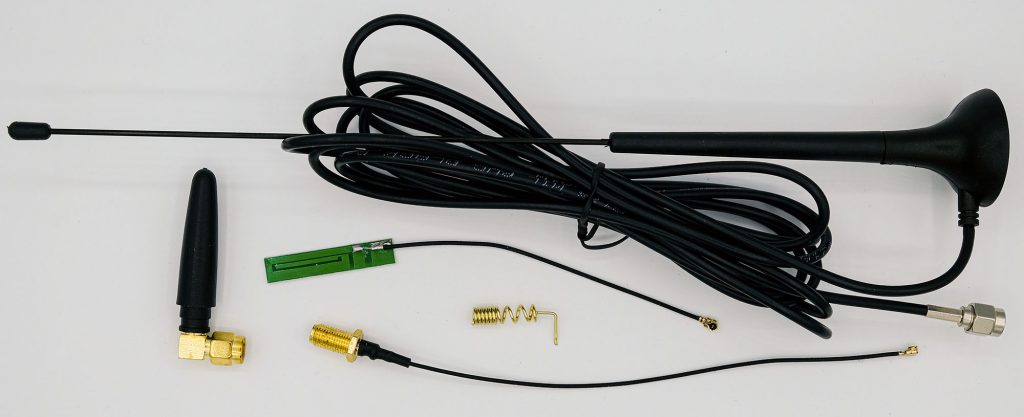
The SIM800L module is normally offered with one or more antennas. In many cases, you can get by with a simple spiral antenna. In areas with poor reception, interfering signals or shielded buildings, you may need a better antenna.
One could also come up with the idea of using two antennas. However, this can be counterproductive, as they might interfere with each other.
If you buy an antenna with an SMA connection (that’s the one with the screw thread), then you still need an IPX UF. L to SMA adapter.
Power consumption
Typical power consumption is:
- Power Down Mode: 60 μA
- Sleep Mode: 0.7 – 1.0 mA
- Normal Mode: (Waiting for SMS or Call): approx. 15 mA
How much power the SIM800L module consumes during a phone call or when transferring data via GRPS is not so easy to answer because the consumption is not constant. I have found quite concrete information here (131 – 216 mA, depending on the frequency band). In my measurements I found values around 70 mA, but with peaks.
At the beginning of a connection, peak values of up to 2 amps can occur, as mentioned above.
Notes on the SIM card
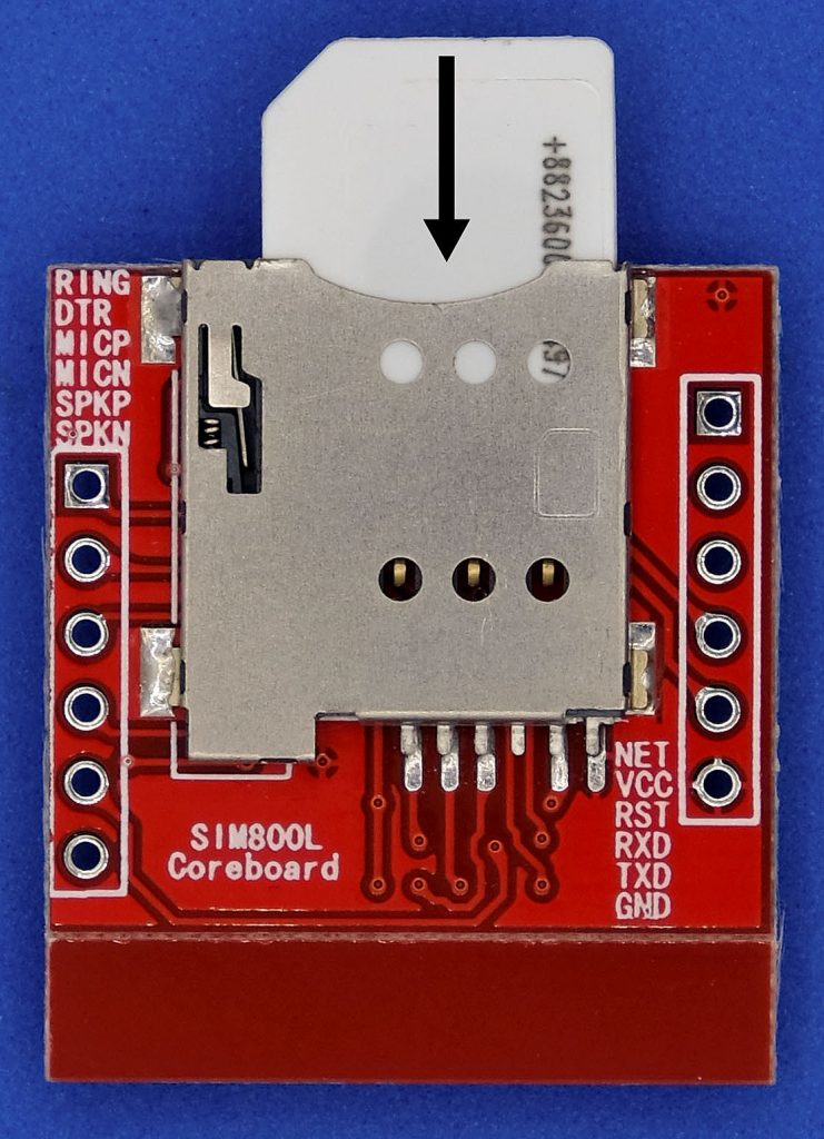
The SIM card is inserted into the cardholder as shown on the right.
I can’t tell you which is the ideal SIM card for you. This depends too much on your application, i.e. mainly on the expected frequency of SMS or calls.
But I want to share an experience with you. I had bought an “IoT and M2M Prepaid” card because it sounded so beautiful. Unfortunately, the card had a “+882” country code, which stands for “International Networks”. This number is blocked by many mobile phone providers because it is also used for fraud calls. In addition, a connection with this area code can generate high costs. So calls were not easily possible, and I could only send SMS from, but not to the module. I then got another SIM card from the good old Telekom. So choose your SIM card wisely.
And be careful when creating programmes to send text messages so that you don’t accidentally send bulk SMS. In the best case, you have a prepaid card, which is then empty.
Wiring of the SIM800L module
This is the wiring I used:
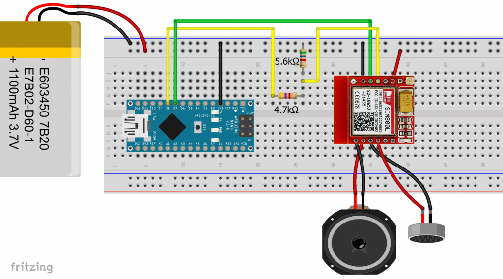
Note that RX of the module is connected to TX of the microcontroller and TX of the module to RX of the microcontroller.
For the above circuit, the voltage at RX of the module is:
![\[ V_{RX}=\frac{5.6}{5.6+4.7}\cdot 5.0\;=\;\sim 2.72\;[\text{V}] \]](https://wolles-elektronikkiste.de/wp-content/ql-cache/quicklatex.com-8e3ccd46ef6b21614fd32d94f155af1b_l3.png "Rendered by QuickLaTeX.com")
Communication via AT commands
One or the other of you may already know AT commands from the HC05 / HC06 Bluetooth modules or other serially controlled components. Most AT commands have this structure (exceptions prove the rule!):
- AT+xxxx: Call of a function or query without parameters
- AT+xxxx=yyyy: Assignment of the value yyyy to the property / function xxxx
- AT+xxxx?: Query the value of xxxx
- AT+xxxx=? Query the options
A list of AT commands for the SIM800L module can be found here. There are over 300 of them in this document alone.
The easiest way is to send the AT commands via the serial monitor of the Arduino IDE to “play around” with them. Alternatively, you can use terminal programs such as PuTTY or HTerm, but then you need a USB-to-TTL adapter.
SoftwareSerial Sketch
Upload the following SoftwareSerial sketch to your Arduino board to communicate via the serial monitor:
#include <SoftwareSerial.h>
SoftwareSerial mySerial(7,8);

void setup() {
  Serial.begin(9600);
  Serial.println("Software Serial Sketch");
  mySerial.begin(9600);
}

void loop() { // run over and over
  while(mySerial.available()) {
    Serial.write(mySerial.read());
  }
  while(Serial.available()) {
    mySerial.write(Serial.read());
  }
}
In my experience, you can work reliably with a baud rate of 9600 bps. At 115200 bps, I lost parts of SMS. In the serial monitor, you need to set the same baud rate and select “Carriage Return (CR)”.
Getting Started
Once you have wired everything, inserted the SIM card and supplied the SIM800L module with power, you can now start. The LED on the SIM800L module should initially light up with a frequency of about 0.8 seconds after the supply voltage is applied.
As a first test, you simply enter AT and confirm with Enter or click on “Send”. The module should respond with a friendly OK. If it does not, then check the wiring and the settings of the serial monitor again.
If everything is OK, you can now query information about the module:
ATI → answer: SIM800 R14.18
Your SIM card may be protected by a PIN. Enter the following:
AT+CPIN? → for answer: +CPIN: READY no PIN is necessary; for answer: +CPIN: SIM PIN you have to enter the PIN including the quotation marks:
AT+CPIN="xxxx" → answer: OK ; if the PIN is incorrect or if the PIN has already been entered: ERROR.
At the latest after entering the correct pin, the module should connect to the network and the LED should flash every 3 seconds.
A very useful feature is to query the battery status:
AT+CBC → answer: +CBC: 0,75,4005
This means: “0” – battery does not charge (“1” would mean the battery charges). “75” means that the battery still has 75% capacity. “4005” stands for 4005 mV voltage.
You can find out the signal strength of your network as follows:
AT+CSQ → answer: +CSQ: 20,0
The first number means:
- “0“: -115 dBm or less
- “1“: -111 dBm
- “2 … 30″: -110 … -54 dBm
- “31“: -52 dBm or greater
- “99“: unknown or not measurable
You can find out which network you are in as follows:
AT+COPS? → answer: +COPS: 0,0,"D1"
The essential information is behind the second comma. So here it is the D1 network. The other numbers encode mode and format. Check out the AT command listfor more information.
This query is also useful:
AT+CREG? → answer: +CREG: 0,1
The second number means: “1” registered, home network; “5” registered, roaming. If you get a 2, 3 or 4, you are not registered.
You can find out your service provider (according to SIM card) by:
AT+CSPN? → answer: +CSPN: "Telekom.de",0
Sleep and Power Down Modes
You activate the power-down mode with:
AT+CPOWD=1 → answer: NORMAL POWER DOWN
With parameter 0, the SIM800L module is switched off immediately and without feedback. Unfortunately, the power-down mode does not seem to be stable. Again and again my module switched itself on after some time. So far, I have not been able to find out the reason.
The sleep mode (slow clock) works better. And this is how the sleep mode is started:
AT+CSCLK=x → answer: +CSCLK: x with x = 0, 1, 2:
- 0: normal (awake) mode.
- 1: Slow Clock Mode 1; To temporarily exit this slow clock mode, set DTR to GND. This is very convenient. When DTR is set to HIGH again, the module goes back into sleep mode. In the normal state, DTR is pulled to HIGH by an internal pull-up resistor.
- 2: Slow Clock Mode 2; to wake up you send
AT+CSCLK=0twice in quick succession.
In sleep mode, the SIM800L module is available for SMS and calls.
How to send SMS
To send an SMS, you may have to enter your PIN and set the module to SMS text mode using AT+CMGF=1. You may have to add a delay to give the module time to connect.
You initiate the actual sending of the SMS by entering the recipient’s telephone number:
AT+CMGS="+491738xxxxxx"
Then a prompt should appear ( > ). You enter the SMS text and complete the input with Ctrl+Z (ASCII code No. 26) and then press Enter. That’s the theory. Practically, I did not manage to send Ctrl+Z via the serial monitor, as it only processes visible characters. But through a sketch (see below) this is no problem. You create a Ctrl+Z with Serial.write(26) .
All other commands are transmitted by Serial.println(). Quotation marks must be preceded by a backslash so that they are not interpreted as the end of the println() statement.
I have outsourced the SoftwareSerial query as a separate function (updateSerial). Since the response to an AT command can take a little time, I have added a waiting time (wt_ms = 100 ms). You may have to adjust the value.
The main loop allows you to enter further commands via the serial monitor. Here you do not need to wait, as you query constantly.
Here’s what the full sketch looks like:
#include <SoftwareSerial.h>
SoftwareSerial mySerial(7,8);
const unsigned int wt_ms = 100; // wait ms

void setup() {
  Serial.begin(9600);
  Serial.println("Send SMS Sketch");
  mySerial.begin(9600);
  delay(1000);
  updateSerial(wt_ms);
  mySerial.println("AT"); // to check if the module is connected
  updateSerial(wt_ms);
  mySerial.println("AT+CPIN=\"xxxx\""); // if Pin is needed
  updateSerial(wt_ms);
//  delay(8000); // maybe needed to setup connection to the network
//  mySerial.println("AT+CCID"); // optional check
//  updateSerial(wt_ms);
//  mySerial.println("AT+CBC"); // optional check
//  updateSerial(wt_ms);
//  mySerial.println("AT+COPS?"); // optional check
//  updateSerial(wt_ms);
//  mySerial.println("AT+CSQ"); // optional check
//  updateSerial(wt_ms);
//  mySerial.println("AT+CREG?"); // optional check
//  updateSerial(wt_ms);
  mySerial.println("AT+CMGF=1"); // SMS text mode
  updateSerial(wt_ms);
  mySerial.println("AT+CMGS=\"+491738xxxxxx\"");
  updateSerial(wt_ms);
  mySerial.print("Hi Wolle, this is a message from your SIM800L Module.");
  updateSerial(wt_ms);
  mySerial.write(26);
  mySerial.println("");
  updateSerial(wt_ms);
}

void loop() {
  updateSerial(0);
}

void updateSerial(unsigned int wait_ms){
  String dataString = "";
  delay(wait_ms);
  if(mySerial.available()) {
    dataString = mySerial.readString();
    Serial.println(dataString);
  }
  while(Serial.available()) {
    mySerial.write(Serial.read());
  }
}
You may have noticed that the answers of the SIM800L module are read in this sketch with mySerial.readString() and stored in a variable. This has the advantage that you can edit or evaluate the module’s response.
Output to serial monitor and smartphone
Here’s what the output looked like:


Evaluating Strings
There are three very useful functions for evaluating and editing strings:
indexOf()/lastIndexOf(): returns the next or last position of the search string within the string. If the string is not found, the functions return -1.parseInt(): searches for the next sequence of numbers in a string and returns it as an integer value.substring(x,y): intersects a sequence from a string (position x to y-1).
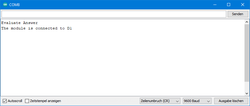
As a small example of the substring() function, I show how you specifically cut out the name of the network from the module response to a “COPS” query. In my case, the “D1″ from +COPS: 0.0,”D1”.
#include <SoftwareSerial.h>
SoftwareSerial mySerial(7,8);
const int wt_ms = 100; // wait ms
String moduleAnswer = "";

void setup() {
  String irg = "AT+COPS";
  Serial.begin(9600);
  Serial.println("Evaluate Answer");
  mySerial.begin(9600);
  delay(1000);

  mySerial.println("AT+COPS?");
  updateSerial(wt_ms);

  moduleAnswer = moduleAnswer.substring(1);   // does not work without, don't know why!
  int pos1 = moduleAnswer.indexOf("\"");      // first position of "
  int pos2 = moduleAnswer.lastIndexOf("\"");  // last position of "
  moduleAnswer = moduleAnswer.substring(pos1+1,pos2);
  Serial.print("The module is connected to ");
  Serial.println(moduleAnswer);
}

void loop(){
}

void updateSerial(unsigned int wait_ms){
  delay(wait_ms);
  if(mySerial.available()) {
    moduleAnswer = mySerial.readString();
  }
  while(Serial.available()) {
    mySerial.write(Serial.read());
  }
}
Why I needed the line:
moduleAnswer = moduleAnswer.substring(1);
I don’t know. Without that, it didn’t work.
How to receive SMS
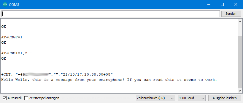
To receive SMS, you must first be connected to the network again and activate the SMS text mode. In addition, you define how incoming SMS are to be handled:
AT+CNMI=1,2.
The parameters used here ensure that the SMS text appears directly on the serial monitor.
#include <SoftwareSerial.h>
SoftwareSerial mySerial(7,8);
const int wt_ms = 100; // wait ms

void setup() {
  Serial.begin(9600);
  Serial.println("Receive SMS Sketch");
  mySerial.begin(9600);
  delay(1000);
  updateSerial(wt_ms);
  mySerial.println("AT+CPIN=\"xxxx\""); // in your SIM card has a PIN
  updateSerial(wt_ms);
  mySerial.println("AT+CREG?"); // optional check
  updateSerial(wt_ms);
  mySerial.println("AT+CMGF=1");
  updateSerial(wt_ms);
  mySerial.println("AT+CNMI=1,2"); // defines how incoming SMS are handled
  updateSerial(wt_ms);
}

void loop() {
  updateSerial(0);
}

void updateSerial(unsigned int wait_ms){
  String bufString = "";
  delay(wait_ms);
  if(mySerial.available()) {
    bufString = mySerial.readString();
  }
  if(bufString != ""){
    Serial.println(bufString);
  }
  while(Serial.available()) {
    mySerial.write(Serial.read());
  }
}
And this is what it looks like on the serial monitor when an SMS is received:
An alternative mode for processing SMS is: AT+CNMI=2,1 (instead of “1.2”). This will ensure that the SMS are saved. You will only get a message on the serial monitor, such as:
+CMTI: "ME",21
This means that SMS No. 21 has been saved in the phone memory (“ME” = Mobile Equipment). You can list the saved SMS with AT+CMGL="ALL":

Instead of “ALL” you can also use “REC UNREAD” (received unread) or “REC READ” (received read) as parameters.
With AT+CMGD=21 you will delete the SMS No. 21. You can also delete all SMS at once. To do this, use the statement AT+CMGDA="DEL ALL".
Controlling the microcontroller via SMS
You can control your microcontroller via SMS. I would like to demonstrate this using the example of two LEDs that I have connected to pins 9 and 10.
Variant 1: with indexOf()
I called the two LEDs led1 and led2. When an SMS is received, the sketch uses the indexOf function to find out whether led1 or led2 is included in the text. Then it searches for the keyword “on”. If this is the case, led1 or led2 is switched on. If no “on” is included, the led1 or led2 is switched off. Examples:
- led1on: led1 is switched on
- blablaled2blablaonblablabla: led2 is switched on
- led1: led1 is turned off.
#include <SoftwareSerial.h>
SoftwareSerial mySerial(7,8);
const int led1_pin = 9;
const int led2_pin = 10;
const int wt_ms = 100; // wait ms

void setup() {
  String moduleAnswer = "";
  Serial.begin(9600);
  Serial.println("Control LED Sketch");
  mySerial.begin(9600);
  pinMode(led1_pin, OUTPUT);
  pinMode(led2_pin, OUTPUT);

  delay(1000);
  updateSerial(wt_ms, moduleAnswer);
  mySerial.println("AT+CPIN=\"xxxx\"");
  updateSerial(wt_ms, moduleAnswer);
  mySerial.println("AT+CREG?");
  updateSerial(wt_ms, moduleAnswer);
  mySerial.println("AT+CMGF=1");
  updateSerial(wt_ms, moduleAnswer);
  mySerial.println("AT+CNMI=1,2");
  updateSerial(wt_ms, moduleAnswer);
}

void loop() {
  String smsText = "";
  updateSerial(0, smsText);

  if(smsText != ""){
    smsText = smsText.substring(1);
    Serial.print("Text: ");
    Serial.println(smsText);
    if(smsText.indexOf("led1")>0){

      if(smsText.indexOf("on")>0){
        digitalWrite(led1_pin, HIGH);
      }
      else{
        digitalWrite(led1_pin, LOW);
      }
    }

    if(smsText.indexOf("led2")>0){
      if(smsText.indexOf("on")>0){
        digitalWrite(led2_pin, HIGH);
      }
      else{
        digitalWrite(led2_pin, LOW);
      }
    }
  }
}

void updateSerial(unsigned int wait_ms, String &bufString){
  bufString = "";
  delay(wait_ms);
  if(mySerial.available()) {
    bufString = mySerial.readString();
  }
  if(bufString != ""){
    Serial.println(bufString);
  }
  while(Serial.available()) {
    mySerial.write(Serial.read());
  }
}
Since strings are quite memory-intensive, I pass “moduleAnswer” and “smsText” as a reference (&bufString). This means that the function works with the original. Accordingly, there is no return value.
Variant 2: with parseInt()
In this variant, the pin and the desired pin state (0 or 1) are directly sent in the SMS text. Examples:
- *10*1*: Pin 10 goes HIGH
- *9*0*: Pin 9 goes LOW
#include <SoftwareSerial.h>
SoftwareSerial mySerial(7,8);
const int led1_pin = 9;
const int led2_pin = 10;
const int wt_ms = 100; // wait ms

void setup() {
  Serial.begin(9600);
  Serial.println("Control LED Sketch");
  mySerial.begin(9600);
  pinMode(led1_pin, OUTPUT);
  pinMode(led2_pin, OUTPUT);

  delay(1000);
  updateSerial(wt_ms);
  mySerial.println("AT+CPIN=\"xxxx\"");
  updateSerial(wt_ms);
  mySerial.println("AT+CREG?");
  updateSerial(wt_ms);
  mySerial.println("AT+CMGF=1");
  updateSerial(wt_ms);
  mySerial.println("AT+CNMI=1,2");
  updateSerial(wt_ms);
}

void loop() {
  waitForSMS();
}

void waitForSMS(){
  int led = 0;
  bool state = false;
  if(mySerial.available()){
    while(((char)mySerial.read())!= '\n'){}
    led = mySerial.parseInt();
    state = mySerial.parseInt();
    digitalWrite(led, state);
  }
}


void updateSerial(unsigned int wait_ms){
  String bufString = "";
  delay(wait_ms);
  if(mySerial.available()) {
    bufString = mySerial.readString();
  }
  if(bufString != ""){
    Serial.println(bufString);
  }
  while(Serial.available()) {
    mySerial.write(Serial.read());
  }
}
Making calls
Making calls with the SIM800L is even easier than sending SMS. Actually, you just have to make sure that your SIM800L module is connected to the net and to set up Serial/SoftwareSerial as with the other sketches:
#include <SoftwareSerial.h>
SoftwareSerial mySerial(7,8);
const int wt_ms = 100; // wait ms

void setup() {
  Serial.begin(9600);
  mySerial.begin(9600);
  Serial.println("Call or wait for a call");
  delay(1000);
  mySerial.println("AT");  // optional check
  updateSerial(wt_ms);
  mySerial.println("AT+CPIN=\"++++\"");
  updateSerial(wt_ms);
  mySerial.println("AT+CREG?"); // optional check
  updateSerial(wt_ms);
}
void loop() {
  updateSerial(0);
}

void updateSerial(unsigned int wait_ms){
  String dataString = "";
  delay(wait_ms);
  if(mySerial.available()) {
    dataString = mySerial.readString();
    if(dataString != ""){
      Serial.println(dataString);
    }
  }
  while(Serial.available()) {
    mySerial.write(Serial.read());
  }
}
Outgoing call
You start a call with the following AT command:
ATD+ +xxxxxxxxxxxx;
Replace xxxxxxxxxxxx with the number to dial, starting with the country code. With ATH you end the call. Don’t forget the semicolon at the end (it’s no spelling mistake!).
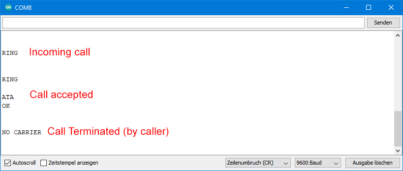
Incoming call
Use the same sketch if you want to call your SIM800L module. The call is indicated acoustically, by “RING” in the serial monitor and by a short LOW signal at the RING pin. You could use the latter signal to wake up your microcontroller from sleep mode. In this way, energy-saving projects can be implemented.
With ATA you take the call, with ATH you reject it.
Telephony settings
Here are some useful functions and settings. You can query the call volume as follows:
AT+CLVL? → answer: +CLVL: 33
And this is how you set the volume:
AT+CLVL=x with x = 0 – 100
The ringtone volume is independent of this (also 0-100):
AT+CRSL? (Query) / AT+CRSL=x (Setting)
There are 20 ringing sounds that you set as follows:
Controlling the microcontroller by call
I thought about how to control the microcontroller by calls. Switching on an LED is easy via “RING”. It is just as easy to turn off the LED with another call. However, it is also easy to get confused. Have I switched it on or off last time? Therefore, it would be nice to get feedback on whether the LED is on or off.
I managed to do that with the following sketch. When a call is received, the sketch checks the status of the LED. If it is switched on, the call will be rejected immediately. If, on the other hand, it is off, nothing happens at first. In both cases, the number of “RINGS” are counted for the next 10 seconds. If the LED was switched off, the call is rejected now. As a result, the sketch counts a different number of “RINGS” depending on the LED state. Accordingly, the LED is switched on or off. And the caller knows that if the call is rejected immediately, the LED was off and is now on.
#include <SoftwareSerial.h>
SoftwareSerial mySerial(7,8);
const int ledPin = 9;
const int wt_ms = 100; // wait ms

void setup() {
  String moduleAnswer = "";
  Serial.begin(9600);
  Serial.println("Control LED by Call");
  mySerial.begin(9600);
  pinMode(ledPin, OUTPUT);
  delay(1000);
  updateSerial(wt_ms, moduleAnswer);
  mySerial.println("AT+CPIN=\"xxxx\""); // in case a PIN is required
  updateSerial(wt_ms, moduleAnswer);
  mySerial.println("AT+CREG?"); // optional check
  updateSerial(wt_ms, moduleAnswer);
}

void loop() {
  String ring = "";
  int noOfRings = 0;
  unsigned long callTime = 0;
  const unsigned long threshold = 10000;

  updateSerial(0, ring);

  if(ring != ""){
    if(ring.indexOf("RING")>0){
      noOfRings++;
      callTime = millis();
      ring = "";
      if(digitalRead(ledPin)){
        mySerial.println("ATH");
      }

      while((millis()-callTime)<threshold){
        updateSerial(0, ring);
        if(ring != ""){
          if(ring.indexOf("RING")>0){
            noOfRings++;
            ring = "";
          }
        }
      }
      if(noOfRings == 1){
        digitalWrite(ledPin, LOW);
      }
      else{
        digitalWrite(ledPin, HIGH);
        mySerial.println("ATH");
      }
    }
  }
}

void updateSerial(unsigned int wait_ms, String &bufString){
  bufString = "";
  delay(wait_ms);
  if(mySerial.available()) {
    bufString = mySerial.readString();
  }
  if(bufString != ""){
    Serial.println(bufString);
  }
  while(Serial.available()) {
    mySerial.write(Serial.read());
  }
}
Attention: A rejected call is not necessarily free of charge! You might, among other things, turn off the setting that the SMS notification service is offered when “busy”. Check this before your phone bill explodes!
Restrict the access – Whitelist
With the SMS and call methods, there is always a risk that someone may unintentionally or maliciously check your SIM800L without authorization. To prevent this, you can set up a whitelist. This allows you to set the phone numbers for which your SIM800L shall be reachable. The SIM800L rejects calls from devices with other phone numbers. The caller receives a busy signal.
Here’s how it works:
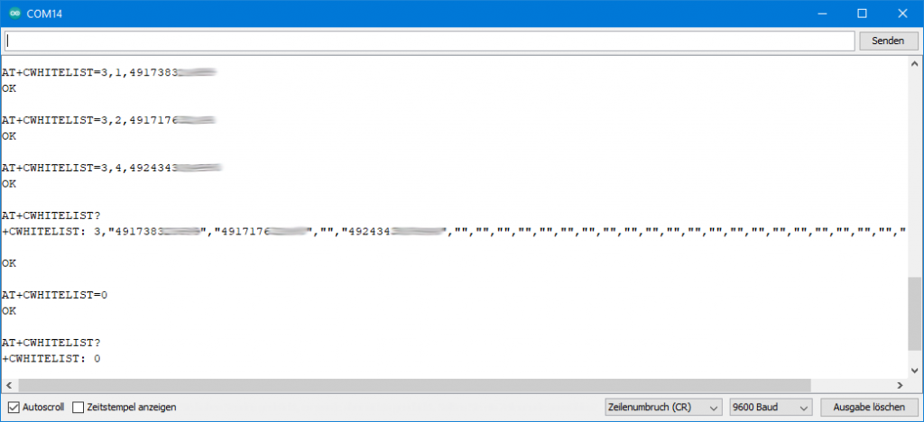
AT+CWHITELIST=mode,index,phone_number
The mode determines whether the whitelist is effective for calls, SMS, or both:
- 0: Whitelist disabled
- 1: Call Whitelist
- 2: SMS Whitelist
- 3: Call and SMS Whitelist
The mode always applies to the entire whitelist. This means that different settings for different numbers are not possible.
Index is the number of the entry (1-30). “phone_number” is the phone number including the country code, but without “+” – as I found out after several hours of experimenting and researching.
AT+CWHITELIST? queries the whitelist and AT+CWHITELIST=0 disables the entire list.
Query the time
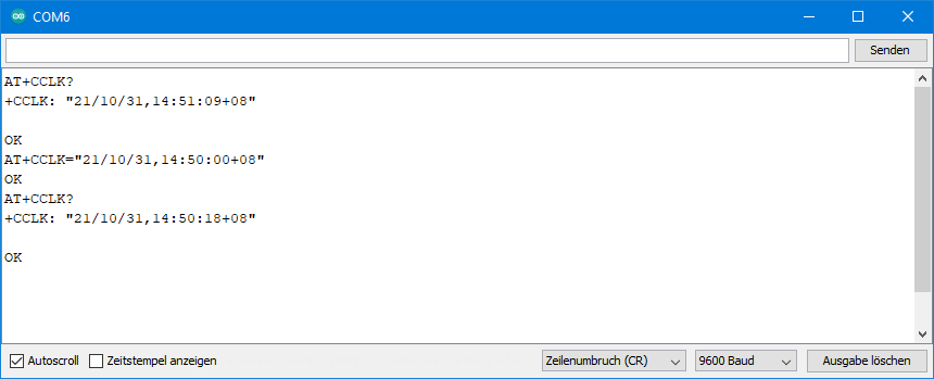
You can use the SIM800L module as an RTC (Real Time Clock). With AT+CCLK? you query the time.
+CCLK: "04/01/01,00:01:31+00"
The format is: “YY/MM/DD,hh:mm:ss±tz”, i.e.“Year/Month/Day,Hours:Minutes:Seconds+tz”, where tz is the deviation from GMT in quarters of an hour. After disconnection from the power supply, the module starts again and again at 00:00 on 01/01/2004. So, you have to set the time. There are three ways to do this:
- Manual setting
- Via the computer’s system time
- Query an NTP server
Manually setting the time
I think the following inputs and outputs on the serial monitor are self-explanatory:
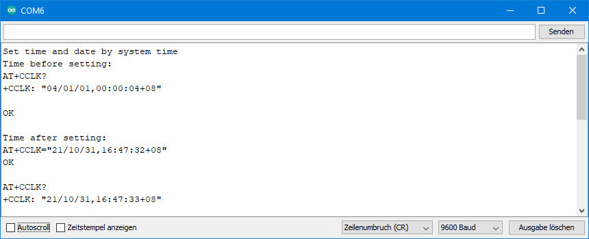
Synchronizing with the computer’s system time
This method uses the computer’s system time to set the time. To do this, you first have to “teach” the microcontroller to handle date and time. The soft-RTC version of the RTCLib is well suited for this. The microcontroller then synchronises with the SIM800L module. I don’t want to go into too much detail. How you work with DateTime and RTC_Millis objects, I have explained in my blog post about the RTC module DS3231.
I just mention this method for completeness. Better is the third method, with which you can set the time whenever and how often you want.
#include "RTClib.h"
#include <SoftwareSerial.h>
RTC_Millis rtc;
SoftwareSerial mySerial(7,8);
const int wt_ms = 100; // wait ms

void setup () {
  Serial.begin(9600);
  mySerial.begin(9600);
  Serial.println("Set time and date by system time");
  delay(1000);
  Serial.println("Time before setting: ");
  mySerial.println("AT+CCLK?");
  updateSerial(wt_ms);
  Serial.println("Time after setting: ");
  rtc.begin(DateTime(F(__DATE__), F(__TIME__))); // sets soft-RTC time by system time
  setTimeBySystemTime();
}

void loop () {
  mySerial.println("AT+CCLK?");
  updateSerial(wt_ms);
  delay(3000);
}

void setTimeBySystemTime(){
  DateTime now = rtc.now();
  String dateTimeString = String(now.year()-2000);
  dateTimeString += "/";
  dateTimeString += byteToStringAndFormat(now.month());
  dateTimeString += "/";
  dateTimeString += byteToStringAndFormat(now.day());
  dateTimeString += ",";
  dateTimeString += byteToStringAndFormat(now.hour());
  dateTimeString += ":";
  dateTimeString += byteToStringAndFormat(now.minute());
  dateTimeString += ":";
  dateTimeString += byteToStringAndFormat(now.second());
  dateTimeString += "+08"; // change according to your time zone
  mySerial.print("AT+CCLK=\"");
  mySerial.print(dateTimeString);
  mySerial.println("\"");
  updateSerial(wt_ms);
}

String byteToStringAndFormat(byte b){
  String str = "";
  str = String(b);
  if(b<10){
    str = "0" + str;
  }
  return str;
}

void updateSerial(unsigned int wait_ms){
  String dataString = "";
  delay(wait_ms);
  if(mySerial.available()) {
    dataString = mySerial.readString();
    if(dataString != ""){
      Serial.println(dataString);
    }
  }
  while(Serial.available()) {
    mySerial.write(Serial.read());
  }
}
Here’s what the output looks like:
Setting the time via NTP server
You can also synchronize the time of the SIM800L with an NTP (Network Time Protocoll) server. This is a GPRS application for which you have to execute a series of “SAPBR” commands. In the sketch I added some comments. Otherwise, please have a look at the AT command list. The “CNTP” commands for the NTP server can be found in a separate document, the NTP Application Note.
#include <SoftwareSerial.h>
SoftwareSerial mySerial(7,8);
const int wt_ms = 100; // wait ms

void setup() {
  Serial.begin(9600);
  mySerial.begin(9600);
  Serial.println("Get Time");
  delay(1000);
  mySerial.println("AT");  // optional check
  updateSerial(wt_ms);
  mySerial.println("AT+CPIN=\"xxxx\""); // if PIN is required
  updateSerial(wt_ms);
  mySerial.println("AT+CREG?"); // optional check
  updateSerial(wt_ms);
  mySerial.println("AT+SAPBR=3,1,\"CONTYPE\",\"GPRS\""); // set GPRS connection
  updateSerial(wt_ms);
  mySerial.println("AT+SAPBR=3,1,\"APN\",\"internet\""); // set APN name
  updateSerial(wt_ms);
  mySerial.println("AT+SAPBR=3,1,\"USER\",\"\""); // username empty
  updateSerial(wt_ms);
  mySerial.println("AT+SAPBR=3,1,\"PWD\",\"\"");  // password empty
  updateSerial(wt_ms);
  mySerial.println("AT+SAPBR=1,1"); // set rate
  updateSerial(wt_ms);
  mySerial.println("AT+SAPBR=2,1");  // connect
  updateSerial(wt_ms);
  mySerial.println("AT+CNTPCID=1"); // set GPRS Bearer Profile’s ID
  updateSerial(wt_ms);
  int timeZone = 2; // local time = UTC + timeZone
  int timeVal = timeZone*4;
  mySerial.print("AT+CNTP=\"0.de.pool.ntp.org\","); // replace by your country ntp server
  mySerial.println(timeVal);
  updateSerial(wt_ms);
  mySerial.println("AT+CNTP"); // synchronize time
  updateSerial(wt_ms);

  mySerial.println("AT+CCLK?"); // query local (module) time
  updateSerial(wt_ms);

  // close connection:
  mySerial.println("AT+SAPBR=0,1");
}

void loop() {
  updateSerial(0);
}

void updateSerial(unsigned int wait_ms){
  String dataString = "";
  delay(wait_ms);
  if(mySerial.available()) {
    dataString = mySerial.readString();
    if(dataString != ""){
      Serial.println(dataString);
    }
  }
  while(Serial.available()) {
    mySerial.write(Serial.read());
  }
}
One more comment about the timeZone: Some time zones do not have full-hour shifts vs GMT. Therefore, the timeshift is passed to the server in quarters of an hour.
Programming the SIM800L module with a library
I had a look at different libraries. GSMSim by Erdem Arslan seemed to be the best. You can install it via the Library Manager or download it directly from GitHub here. However, the example sketches do not work “out of the box” on an Arduino UNO. Below you will find the modified example sketch for sending SMS.
#include <GSMSimSMS.h>
#include <SoftwareSerial.h>
#define RESET_PIN 10 // you can use any pin.

SoftwareSerial Serial1(6,7);
GSMSimSMS sms(Serial1, RESET_PIN); // GSMSimSMS inherit from GSMSim. You can use GSMSim methods with it.

void setup() {
  Serial1.begin(9600); // If you don't change module baudrate, it comes with auto baudrate.
  Serial.begin(9600); // Serial for debug...

  // Init module...
  sms.init(); // use for init module. Use it if you don't have any valid reason.

  Serial.print("Set Phone Function... ");
  Serial.println(sms.setPhoneFunc(1));
  delay(1000);

  //Serial.println("Enter Pin Code:...");
  //Serial.println(sms.enterPinCode("xxxx"));
  //delay(3000);

  Serial.print("is Module Registered to Network?... ");
  Serial.println(sms.isRegistered());
  delay(1000);

  Serial.print("Signal Quality... ");
  Serial.println(sms.signalQuality());
  delay(1000);

  Serial.print("Operator Name... ");
  Serial.println(sms.operatorNameFromSim());
  delay(1000);

  Serial.print("Init SMS... ");
  Serial.println(sms.initSMS()); // Its optional but highly recommended. Some function work with this function.
  delay(1000);

  Serial.print("List Unread SMS... ");
  Serial.println(sms.list(true)); // Its optional but highly recommended. Some function work with this function.
  delay(1000);

  Serial.print("SMS to any number... ");
  Serial.println(sms.send("+49173xxxxxxx", "SMS test message")); // only use ascii chars please
  delay(1000);
}

void loop() {
}
All in all, however, I would advise working without a library. You are simply more flexible.
Annex: GSM Location – an attempt
Theoretically, the location of the SIM800L can be determined. To anticipate it, I finally get a “Location Error”. It could be that this is related to my location, and that it works elsewhere. Usually, I don’t publish anything that might work. However, since I have invested many hours in this problem and could solve some partial aspects that others had problems with, I would like to share my experience.
CIPGSMLOC has stopped working
With the AT command AT+CIPGSMLOC=1,1 and some preparatory settings, it was possible until some time ago to determine the location in longitude and latitude. However, the method is based on a service that has unfortunately been switched off. This path is therefore blocked.
Alternatively, there are the “CLBS” AT commands described in the Location_Application_Note. However, this requires an update of the firmware of the SIM800L.
Firmware update to version 1418B05SIM800L24
Preparations
On the hardware side, you need a USB-to-TTL adapter, which you can get for a few Euros at Amazon and Co. Then you need the firmware version 1418B05SIM800L24. You can find it here on GitHub, for example. Download the ZIP file and unzip it somewhere. Furthermore, you need the program SIM800_Series_download_Tools_Customer_v1.19 to upload the firmware. This is available here. Download and unzip the rar file. It doesn’t matter which folder you use. In the unzipped folder you will find the program Flash_tool.exe.
Wire your hardware as follows:

The voltage divider (5.6 kΩ / 4.7 kΩ) is for a 5V adapter. As mentioned above, there are voices that say the SIM800L pins are 5V tolerant. You have to decide for yourself how careful you want to be.
Uploading the firmware
Now launch Flash_tool.exe. Click on “Image Folder” and select the previously downloaded and unzipped firmware file. Set SIM800L, UART and baud rate 115200. As “Com” you select the port of your adapter. “Erase Type” is “Erase Source Code And User Data”:
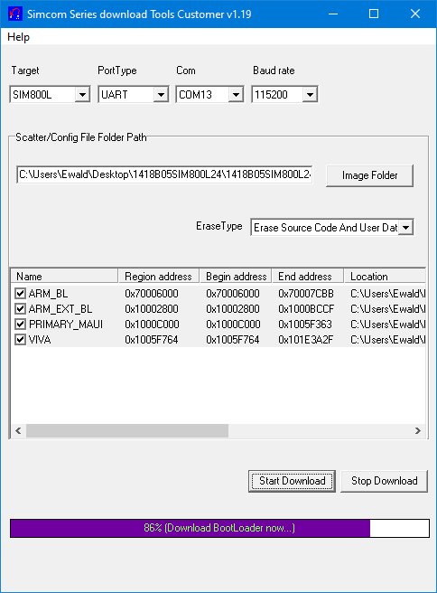
Click on “Start Download”. Then you take the SIM800L briefly from the power and reconnect it. The upload (called download here) should start in about 10 seconds.
After a few minutes, the firmware is on the module. Disconnect the module from power again and restart it.
Attempt to determine the location

With the following sketch, everything seems to work, up to the actual location request AT+CLBS=1,1. The answer is +CLBS: 1. According to the error list, this is “Location Failed”. Maybe something needs to be set differently, or maybe it has to do with the net coverage where I live. Or has the service been discontinued? I parked the whole thing in my X-Files folder.
#include <SoftwareSerial.h>
SoftwareSerial mySerial(7,8);
const int wt_ms = 100; // wait ms

void setup() {
  Serial.begin(9600);
  mySerial.begin(9600);
  Serial.println("Get Location");
  delay(1000);
  mySerial.println("AT");  // optional check
  updateSerial(wt_ms);
  mySerial.println("AT+CPIN=\"xxxx\""); // if PIN is required
  updateSerial(wt_ms);
  mySerial.println("AT+CREG?"); // optional check
  updateSerial(wt_ms);
  mySerial.println("AT+SAPBR=3,1,\"CONTYPE\",\"GPRS\""); // set GPRS connection
  updateSerial(wt_ms);
  mySerial.println("AT+SAPBR=3,1,\"APN\",\"internet\""); // set APN name
//  updateSerial(wt_ms);
//  mySerial.println("AT+SAPBR=3,1,\"USER\",\"\""); // username empty
//  updateSerial(wt_ms);
//  mySerial.println("AT+SAPBR=3,1,\"PWD\",\"\"");  // password empty
  updateSerial(wt_ms);
  mySerial.println("AT+SAPBR=1,1"); // set rate
  updateSerial(wt_ms);
  mySerial.println("AT+SAPBR=2,1");  // connect
  updateSerial(500);
  mySerial.println("AT+CLBSCFG=0,1");
  updateSerial(500);
  mySerial.println("AT+CLBSCFG=0,2");
  updateSerial(wt_ms);
  mySerial.println("AT+CLBSCFG=0,3");
  updateSerial(wt_ms);
  mySerial.println("AT+CLBSCFG=1,3,\"lbs-simcom.com:3002\"");
  updateSerial(500);
  mySerial.println("AT+CLBS=1,1");
  updateSerial(500);
  delay(10000);

  //close connection:
  mySerial.println("AT+SAPBR=0,1");
}

void loop() {
  updateSerial(0);
}

void updateSerial(unsigned int wait_ms){
  String dataString = "";
  delay(wait_ms);
  if(mySerial.available()) {
    dataString = mySerial.readString();
    if(dataString != ""){
      Serial.println(dataString);
    }
  }
  while(Serial.available()) {
    mySerial.write(Serial.read());
  }
}
Acknowledgement
Again, I used some images from Pixabay for my post image. Many thanks to the creators:
- Smartphone: Leo Romero
- Call icon: Memed_Nurrohmad
- SMS symbol: OpenClipart-Vectors
- Arduino: Seven_au
- Arrows: Clker Free Vector Images
I got the SIM800L from Andrey Fedorov on GitHub.
Здравствуйте, хороший обзор на модуль. Ищу режим сна модуля sim800l и Arduino, система просыпается по звонку отправляет данные и уходит в сон?
Здравствуйте, в спящем режиме модуль просыпается для звонков и текстовых сообщений. Затем вы можете вернуть его в спящий режим. Насколько я знаю, в спящем режиме он недоступен. Надеюсь, этот перевод имеет смысл!
Hi Wolle, thank you for your special and interesting tutorial. You are a good teacher
Thank you so much – this is very kind!
Hi Wolle ! I hope you’re doing well ! Thank you for your post on libraries ! as always : a clear and practical explanation, applicable on-the-spot knowledge ! Wonderful. It brought me back to my workshop and continue this great hobby !
I write this comment in the SIM800L post, because I have a question about a AT command issue : I’m using an ESP32 with embedded SIM800L, library GSMSim by Erdem Arslan.
Because I do not always have Internet available, I want to get time from the gsm network.
I send command AT+CLTS=1, check with AT+CLTS?, store it in the module’s memory with AT&W, but I keep getting the same (default) time, like 04/01/01,00:00:30+04 after AT+CCLK? command.
Maybe you have any idea what might be the reason ?
Many thanks for any response !
Ronald
Hi Ronald,
not sure. Maybe I find the time to try myself in the next days, but I won’t promise! There is a note in the datasheet which says: “Support for this Command will be network dependent”. Could this be the issue?
Best wishes, Wolfgang
Thanks for an almost complete tutorials on the SIM800L. I have searched everywhere. But I got this site which turns very best for me. this site teach 1st about connection, then basic command, then complex and finally a Firmware update which also very much required for a person like me. I have a SIM800L module which was bricked by installing worng firmware with worng tool. I found that with version: 1308B09SIM800L16 and tool (1.06), my module returns to the normal and light now glow.
Thanks you made my day…
Thanks a lot again.
Thanks for your kind feedback which is very motivating for me!
Oohh yes. It was exactly what I wanted.
Thank You.
🙂 Thanks for the feedback!
Very cool tutorial! Helped me quite a bit when setting up the module.
FYI
I was able to determine the location of the module with your tutorial 😉 (quite accurately to be honest :D)
Thanks for the feedback, much appreciated!
Very interesting blog page, accurate and simple to read. Thank you.
Thank you!
I’ve stumbled across your blog, It’s very refreshing to find such informative articles written “in plain English” as we say. I didn’t know about the SIM800L, I’m going to have some fun with it.
Thank you
By the way, the English in your articles is immaculate, I find the Web pages more difficult.
John
Thank you for your kind feedback!