About this Post
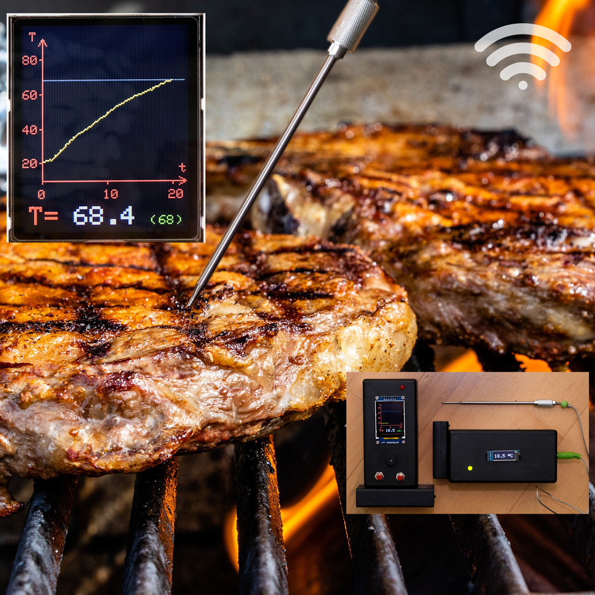
Normally, my posts are of a more basic nature, but here I would like to present a very concrete project of mine, namely a wireless BBQ thermometer with graphical display of the temperature curve.
In winter, I find it especially nice to have a good piece of meat on the grill while sitting inside, drinking a wine and watching the temperature of the food. And if you can do the latter with your self-made device, it’s even more fun. Do you need a graphical display? No, of course not, but it’s exciting, and you can show off!
Probe for the wireless BBQ thermometer
To build a BBQ thermometer, you first need a suitable temperature probe. You can get these under the search term “replacement probe” for 5 to 15 euros in online shops such as Amazon.
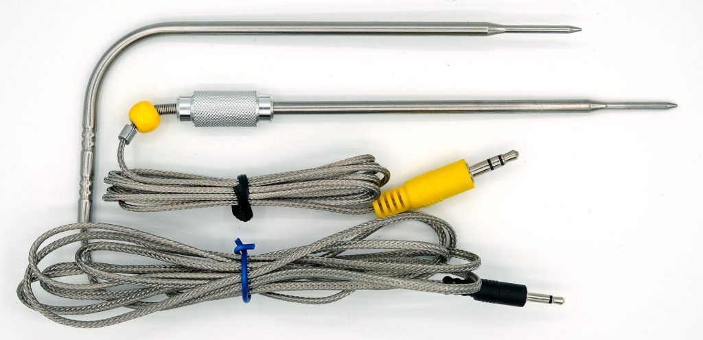

In most cases, the probes have a 2.5 or 3.5 mm jack plug as connection. Whether the plug has two or three poles does not matter because usually only two of them are active. There are corresponding sockets that you can install in the housing of the transmitter unit of your thermometer.
The probes are based on a temperature-dependent resistor. Unfortunately, the resistance value does not change linearly with temperature and, moreover, each model is different. Calibration is therefore unavoidable. To do this, record a temperature-resistance curve with a known and reliable thermometer. A first test with my multimeter showed that the resistance at 0 °C was 330 kΩ. At room temperature it was about 120 kΩ, at 100 °C it dropped to 6.3 kΩ. This is far from any linearity.
Measurement of the thermometer resistance
Theory
Theoretically, you can measure the resistor values for the temperature-resistance curve directly with a multimeter. In practice, it is better to measure the resistor values as you do later in your circuit. The advantage is that this way you can compensate for errors such as possible non-linearity of your A/D converter.
The basis for determining resistance is Ohm’s law:
![\[ U = R\cdot I\;\;\;\;\;\text{or:}\;\;\;\;\;\frac{U}{R}=I \]](https://wolles-elektronikkiste.de/wp-content/ql-cache/quicklatex.com-605849ffc46ab9e1f6b38a500c85b377_l3.png "Rendered by QuickLaTeX.com")
Voltages can easily be measured with ADCs, currents are more complicated, especially as they are extremely low for these resistance dimensions. Therefore, I use a second, known resistor (reference), which I connect in series with the thermometer. Since the current is the same for both resistors, the following applies:
![\[ \frac{U_{\text{thermometer}}}{R_{\text{thermometer}}}= I = \frac{U_{\text{reference}}}{R_{\text{reference}}}\;\;\;\;\;\;\;\Rightarrow\;\;\;\;\;\;\;R_{\text{thermometer}}=\frac{U_{\text{thermometer}}}{U_{\text{reference}}}\cdot R_{\text{reference}} \]](https://wolles-elektronikkiste.de/wp-content/ql-cache/quicklatex.com-259a93c231a29172fecbf354b7cbb447_l3.png "Rendered by QuickLaTeX.com")
In order to achieve a good resolution over the entire range in the temperature measurements, the size of the reference resistor should correspond to the thermometer resistance somewhere in the middle of the temperature measurement range. I selected 33 kΩ.
Practice
I wanted to measure as accurately as possible and therefore chose a reliable, external ADC, namely the ADS1115. A few years ago, I built a version 1.0 of this BBQ thermometer using the internal ADC of an Arduino Nano. With this, I was able to achieve an accuracy of +/- 1 degree. So this is also possible and there is less soldering to do later – your choice.
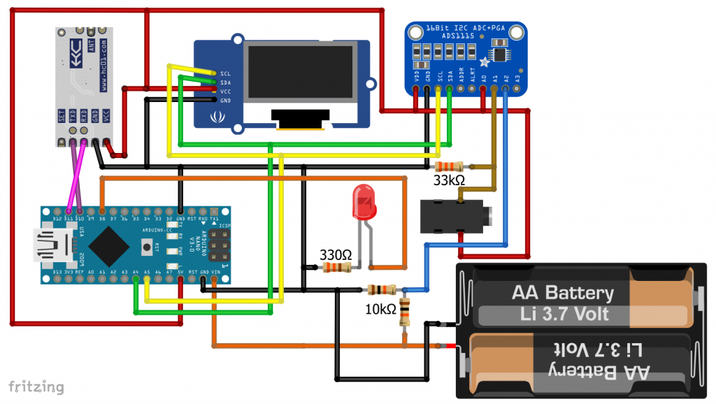
I used the following circuit to record the calibration curve:
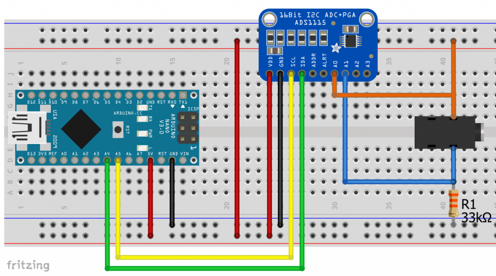
So, here I measure the total voltage and the voltage drop across the reference resistor. Uthermometer is the difference.
The temperature sensor is represented in the circuit diagram by the connection socket. Add it to your thoughts. And here is the sketch:
#include<ADS1115_WE.h>
#include<Wire.h>
#define I2C_ADDRESS 0x48
const float constResistorVal = 32.8; // 32.8 kOhm

ADS1115_WE adc = ADS1115_WE(I2C_ADDRESS);

void setup() {
  Wire.begin();
  Serial.begin(115200);
  if(!adc.init()){
    Serial.println("ADS1115 not connected!");
  }
  adc.setMeasureMode(ADS1115_CONTINUOUS); // Continuous Mode
  adc.setPermanentAutoRangeMode(true);  // Autorange Mode
}

void loop(){
  float supplyVoltage = 0.0;
  float resistorVoltage = 0.0;
  float thermometerVoltage = 0.0;
  float thermometerResistance = 0.0;

  Serial.print("Supply Voltage [V]: ");
  supplyVoltage = readChannel(ADS1115_COMP_0_GND);
  Serial.println(supplyVoltage);

  Serial.print("Resistor Voltage [V]: ");
  resistorVoltage = readChannel(ADS1115_COMP_1_GND);
  Serial.println(resistorVoltage);

  Serial.print("ThermometerVoltage [V]: ");
  thermometerVoltage = supplyVoltage - resistorVoltage;
  Serial.println(thermometerVoltage);

  Serial.print("Thermometer Resistance [kOhm]: ");
  thermometerResistance = thermometerVoltage/resistorVoltage * constResistorVal;
  Serial.println(thermometerResistance);

  Serial.println();
  Serial.println("-------------------------------");
  Serial.println();
  delay(500);
}

float readChannel(ADS1115_MUX channel) {
  float volts = 0.0;
  adc.setCompareChannels(channel);
  for(int i=0; i<10; i++){
    volts += adc.getResult_V();
  }
  return volts/10;
}
If you want to use the internal ADC of your board, you have to modify the sketch accordingly.
For the measurement, I simply brought a pot of water to the boil and then measured the resistance and temperature as it cooled. This is trickier than you might think – you quickly have temperature zones in the pot and should therefore stir. Also, the tips of the thermometers should not touch the bottom of the pot, as shown in the photo. I just didn’t have enough hands while taking pictures.
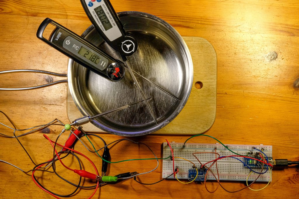
In the beginning, the temperature drops quickly, then slower and slower. Therefore, after a while I added cold water in portions. Ich habe Eiswürfel für den Bereich von Raumtemperatur bis 0 Grad verwendet.
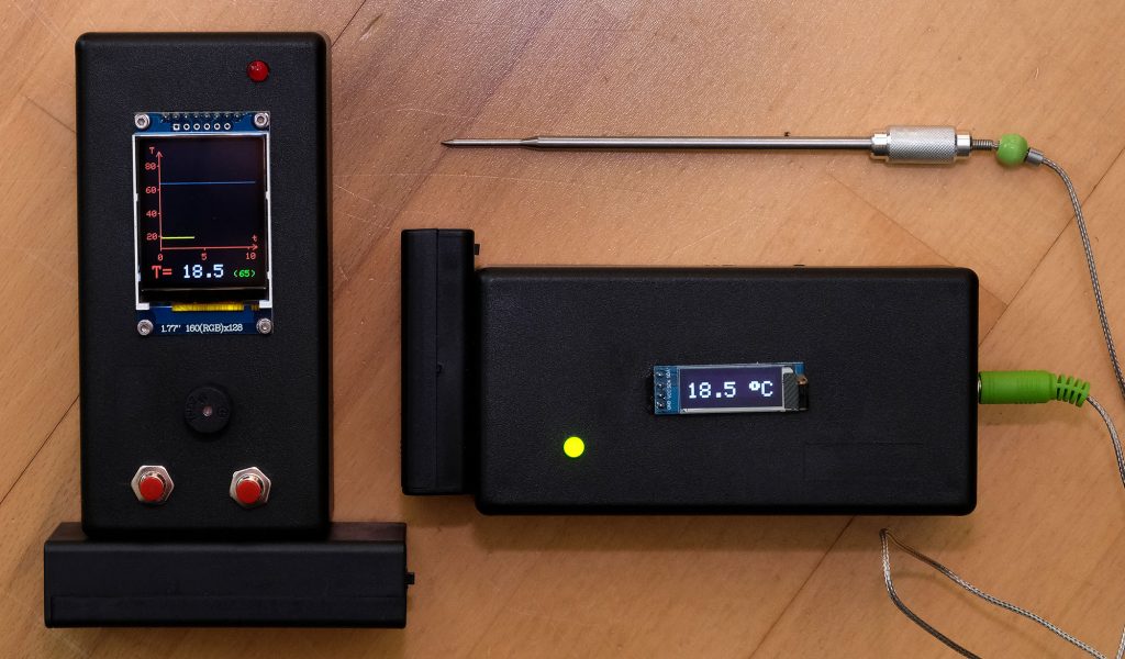
The quality of the calibration can only be as good as the quality of your reference thermometer. As can be seen in the photo above, the two barbecue thermometers differ by one degree. Don’t trust all devices just because they are digital!
Evaluation of the calibration curve for the wireless BBQ thermometer
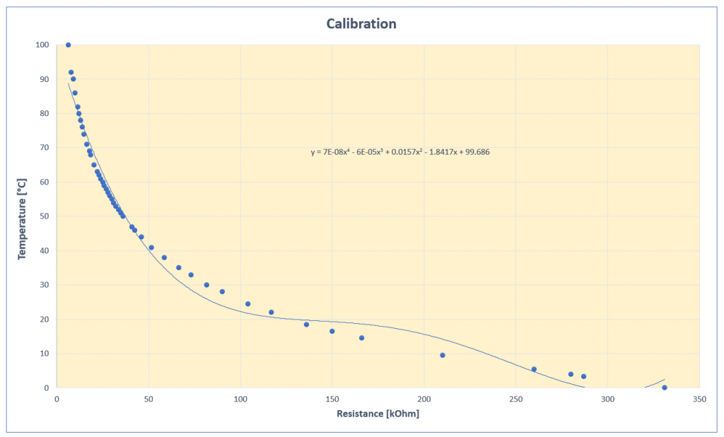
I entered the measured pairs of temperature and resistance into Excel and created a graph. Then I tried to put a regression curve through the values. In Excel, these are called “trendlines”. To display trend lines, left-click a data point, then right-click and select “add trendline”. Then you can choose which type of function you want to use. Check the box “Display Equation on chart”.
Neither a logarithmic function nor a polynomial was a really good fit:
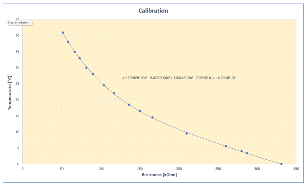
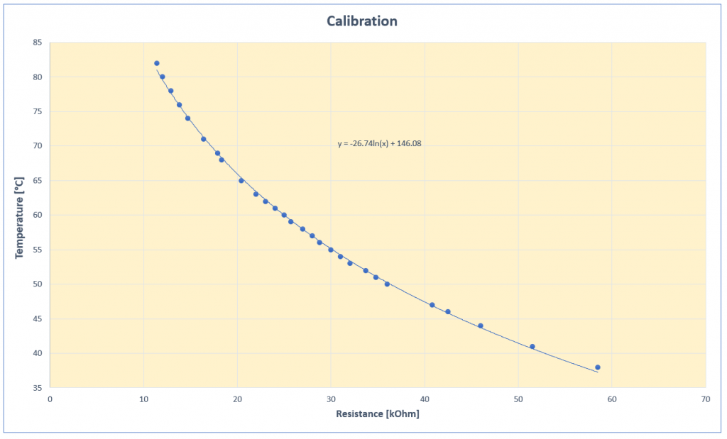
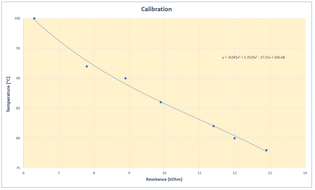
It was only when I divided the curve into three parts that I was satisfied with the trend lines. The diagrams are a bit small. Click on the images to enlarge them:
Another hint: Do not blindly adopt the trend lines in your sketches. Especially with higher order polynomials, often not enough decimal places of the coefficients are displayed (as in the calibration curve 0-100°C above). Right-click the formula in the chart and select the bars (Format Trendline Label) on the right side. There, you select the category “Scientific” and choose an appropriate number of decimal places.
You should check the reliability and enter some resistance values in the trendline functions and compare the results with your readings. I tested the trendline functions this way:
float r = 331.0; // resistance
float temperature = 0.0;

void setup() {
  Serial.begin(115200);
  for(int i=0; i<140; i++){
    r = r - 2.0;
    temperature =  8.731*pow(r,4)*pow(10,-9) - 9.025*pow(r,3)*pow(10,-6)+ 0.00354*pow(r,2)- 0.709*r + 69.094;
    Serial.print("R: ");
    Serial.print(r);
    Serial.print(",   T:");
    Serial.println(temperature);
  }
  Serial.println("********************");
  r = 60.0;
  for(int i=0; i<49; i++){
    r = r - 1.0;
    temperature = -26.74*log(r) + 146.08;
    Serial.print("R: ");
    Serial.print(r);
    Serial.print(",   T:");
    Serial.println(temperature);
  }
  Serial.println("********************");
  r = 13.0;
  for(int i=0; i<15; i++){
    r = r - 0.5;
    temperature = -0.041*pow(r,3) + 1.3525*pow(r,2) - 17.51*r + 166.68;
    Serial.print("R: ");
    Serial.print(r);
    Serial.print(",   T:");
    Serial.println(temperature);
  }
  Serial.println("********************");
}

void loop() {
}
If everything is in order, you have completed the main part of the wireless barbecue thermometer.
The transmitter unit
Concept of the transmitter unit
In addition to temperature measurement, the transmitter unit shall:
- output the temperature on a display,
- send the temperature to the receiver unit by radio every few seconds,
- monitor the battery voltage.
I chose a small 128×32 px OLED model for the display, which is controlled via I2C.
For radio transmission, I chose the 433 MHz module HC-12, which I have described in detail here. It is characterized by a long range and simple control via software serial.
For the power supply, I use two 3.7 volt lithium-ion batteries connected in series to VIN of the Arduino Nano. Since the ADC only detects up to 5 volts, I measure the voltage via a voltage divider (2 x 10 kΩ).
An LED lights up continuously when the battery voltage is still OK (> = 7.2 volts), otherwise it flashes.
This is the circuit:
About the power supply concept for the radio barbecue thermometer
Lithium-ion batteries in AA design (14500) are somewhat unusual. The advantage is that battery cases with on/off switches are available. A disadvantage, however, is that you need a special charger. Furthermore, you have to be careful that you strictly separate them from your Ni-Mh batteries. Because if you use them in the wrong devices, you can destroy them. And when it comes to capacities, suppliers exaggerate excessively.
For the receiver unit (to anticipate), which consumes more power because of the larger display, I used large 18650 lithium-ion batteries. These are more likely to deliver what is promised in terms of capacity. Of course, you also need a special charger for them. And battery cases are a little harder to get.
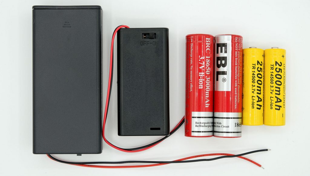
For my wireless BBQ thermometer version 1.0, I had used three Ni-Mh rechargeable batteries and a step-up converter – this is also possible. Other alternatives are 9 V block batteries or a 6-pack of Ni-Mh batteries.
Another hint: The VIN connection reacts very allergic to polarity reversal. Your Arduino Nano will die immediately. Especially with 9 volt blocks, this can easily happen. A short contact is enough. For safety, you could add a diode to your circuit.
Sketch for the transmitter unit
The sketch for the transmitter unit of the wireless BBQ thermometer is not particularly complex. However, it uses a number of libraries that I can’t go into in detail. But I think that the sketch is still reasonably understandable.
#include <ADS1115_WE.h>
#include <Wire.h>
#include <Adafruit_GFX.h>
#include <Adafruit_SSD1306.h>
#include <SoftwareSerial.h>

#define OLED_RESET 7 // we don't have a reset, but the constructor expects it
#define I2C_ADDRESS 0x48
const int ledPin = 8;
const float constResistorVal = 32.8;

SoftwareSerial hc12(10,11);
Adafruit_SSD1306 display(OLED_RESET);
ADS1115_WE adc = ADS1115_WE(I2C_ADDRESS);

void setup() {
  pinMode(ledPin, OUTPUT);
  digitalWrite(ledPin, HIGH);
  Wire.begin();
  Serial.begin(115200);
  hc12.begin(9600);
  if(!adc.init()){
    Serial.println("ADS1115 not connected!");
  }
  adc.setMeasureMode(ADS1115_CONTINUOUS);
  adc.setPermanentAutoRangeMode(true);

  display.begin(SSD1306_SWITCHCAPVCC, 0x3C);  // initialize with the I2C addr 0x3C (for the 128x64)
  display.clearDisplay();
  display.setTextSize(3);
  display.setTextColor(WHITE);
  display.setCursor(10,4);
  display.println("Wait");
  display.display();
}

void loop(){
  float supplyVoltage = 0.0;
  float resistorVoltage = 0.0;
  float thermometerVoltage = 0.0;
  float thermometerResistance = 0.0;
  float batteryVoltage = 0.0;

  Serial.print("Supply Voltage [V]: ");
  supplyVoltage = readChannel(ADS1115_COMP_0_GND);
  Serial.println(supplyVoltage);

  Serial.print("Resistor Voltage [V]: ");
  resistorVoltage = readChannel(ADS1115_COMP_1_GND);
  Serial.println(resistorVoltage);

  Serial.print("ThermometerVoltage [V]: ");
  thermometerVoltage = supplyVoltage - resistorVoltage;
  Serial.println(thermometerVoltage);

  Serial.print("Thermometer Resistance [kOhm]: ");
  thermometerResistance = thermometerVoltage/resistorVoltage * constResistorVal;
  Serial.println(thermometerResistance);

  Serial.print("Battery Voltage [V]: ");
  batteryVoltage = readChannel(ADS1115_COMP_2_GND) * 2;
  Serial.println(batteryVoltage);

  Serial.print("Temperature [°C]: ");
  float temperature = calcTemp(thermometerResistance);
  Serial.println(temperature);

  displayAndSendTemperature(temperature);
  if(batteryVoltage <= 7.2){
    digitalWrite(ledPin, LOW);
    delay(500);
    digitalWrite(ledPin, HIGH);
  }
  Serial.println();
  Serial.println("-------------------------------");
  Serial.println();
  delay(2500);
}

void displayAndSendTemperature(float tC){
  String tCString = "";
  tCString = String(tC,1) + " ";
  hc12.print(tCString);
  tCString += char(247);  // ASCII No 247 = "°"
  tCString += "C";
  display.clearDisplay();
  display.setCursor(0,11);
  display.println(tCString);
  display.display();
}

float calcTemp(float r){
  float tC = 0.0; // temperature Celsius
  if(r < 11.5){
    tC = -0.041*pow(r,3) + 1.3525*pow(r,2) - 17.51*r + 166.68;
  }
  else if(r < 55.0){
    tC = -26.74*log(r) + 146.08;
  }
  else{
    tC = 8.731*pow(r,4)*pow(10,-9) - 9.025*pow(r,3)*pow(10,-6)+ 0.00354*pow(r,2)- 0.709*r + 69.094;
  }
  return tC;
}

float readChannel(ADS1115_MUX channel) {
  float volts = 0.0;
  adc.setCompareChannels(channel);
  for(int i=0; i<10; i++){
    volts += adc.getResult_V();
  }
  return volts/10;
}
Just a few explanations:
- The ADS1115 measures the voltages from which the thermometer resistance is calculated.
- In addition, the ADS1115 measures the battery voltage.
- The calcTemp() function uses the calibration trendlines to calculate the temperature.
- The temperature is converted into a string and output on the display.
- The HC-12 sends the temperature to the receiver unit (simply with
hc12.print()) - If the battery voltage drops below 7.2 volts, the LED is switched off for half a second.
- After a delay of 2.5 seconds, the cycle starts again.
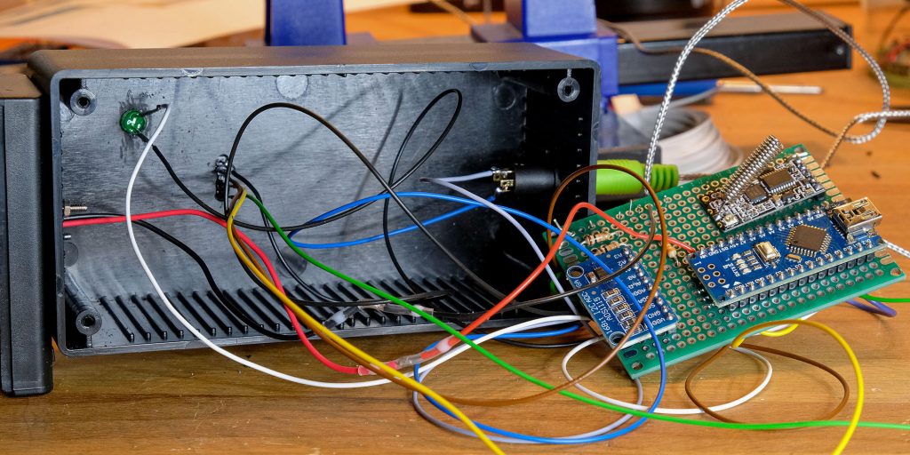
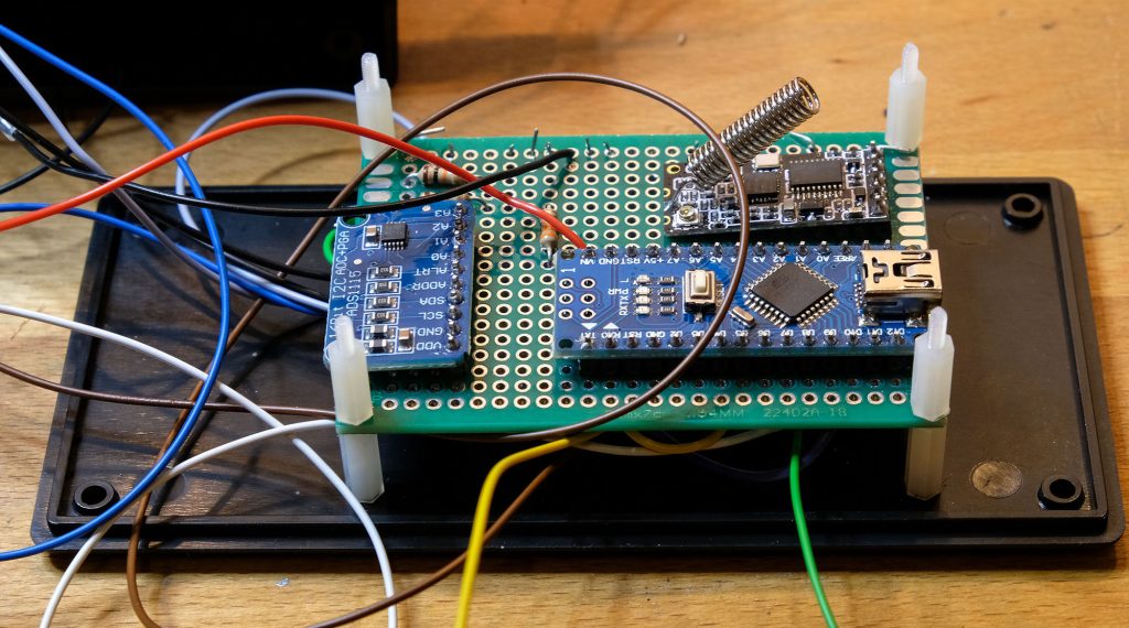
Construction of the transmitter unit
I have installed the transmitting unit in an electronic housing. I could also have chosen a smaller housing. The ADC, the Arduino Nano, the resistors and the HC-12 module were placed on a PCB, which in turn was attached to the baseplate with spacers.
I screwed the battery housing to the main housing and routed the cables for the supply voltage inside. The cables were led through an additional hole into the “main housing” and are thus no longer visible from the outside.
I had to create more openings for the LED, the socket for the temperature sensor and the pin header of the display. Plastic is not the nicest material for handicrafts because it melts at the contact points during drilling. But it works. It was a bit more difficult to create the opening for the pin header of the display. A Dremel multi tool kit has served well here.
Now, when rebuilding the project, you can use a second microcontroller and another HC-12 module and / or an LED to check whether the transmission is working or also to check the range.
void setup() {
  Serial.begin(115200);
  hc12.begin(9600);
  pinMode(ledPin, OUTPUT);
  Serial.println("BBQ Receive Test");
}

void loop(){
  String message = "";
  if(hc12.available()) {
    message = hc12.readString();
    Serial.println(message);
    if(message.indexOf(".")){  // sense check
      digitalWrite(ledPin, HIGH);
      delay(500);
      digitalWrite(ledPin, LOW);
    }
  }
}
This completes the transmitter unit. Even without a receiver unit, you already have a functioning, digital BBQ thermometer.
The receiver unit for the wireless BBQ thermometer
Concept of the receiver unit
The receiver unit shall:
- receive the readings from the sending unit and display them as a value
- graphically display the temperature curve
- output an acoustic warning at a selectable target temperature
- use an LED to indicate when the battery voltage drops below 7.2 volts
I have again chosen an Arduino Nano as the microcontroller.
I decided to use a 128×160 px TFT display with integrated ST7735 controller. It is controlled via SPI. Since the controller is not 5 volt tolerant, a levelshifter is required when using an AVR-based Arduino. A pinout scheme for the display I use can be found here. An introduction to this can be found here, but the non-compatibility with 5 volts is ignored in this article. I used the 8-channel TXB0108 as the level shifter.
The temperature alert is output with a 5 volt buzzer. The buzzers are not excessively loud, but cheap to buy and can be controlled directly via an Arduino pin.
The temperature alarm is set via two push-buttons. My choice fell on a screw-in construction that is used in model railways, among other things.
I had already discussed the power supply above.
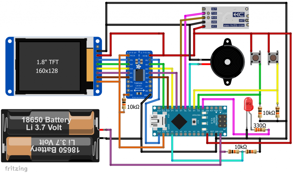
Sketch for the receiver unit
The sketch for the receiver unit is more complex than the one for the transmitter unit. It’s also too long for me to explain line by line. A few explanations follow, but first the sketch:
#include <TFT.h>
#include <SoftwareSerial.h>

// TFT settings(Arduino Nano): SDA - 11, SCK - 13
#define CS 10 // Chip Select
#define DC 8
#define RESET 9
#define ALERTPIN 5
#define LED_PIN 2
#define CC_X_BEGIN 15
#define CC_X_END   125
#define CC_Y_BEGIN 10
#define CC_Y_END   120

enum tftColor{RED=1, GREEN, YELLOW, BLUE, LIGHTBLUE, GREY, BLACK};

TFT myScreen = TFT(CS, DC, RESET);
SoftwareSerial hc12(6,7);

float pixelsPerDegree = CC_Y_END/90.0; // Scaling of the T-axis (10.0 - 100.0 °C) -> constant
unsigned int secsPerXPixel = 6;  // Scaling of the t-axis -> changes over time
int targetT = 55;        // target temperature
int valCounter = 0;      // counter for measured values
byte coordPair[105][2];  // coordinates time/temperature in pixels
bool alert = true;       // alert, when target temperature is reached

void setup(){
  pinMode(ALERTPIN,OUTPUT);
  pinMode(LED_PIN, OUTPUT);
  Serial.begin(115200);
  hc12.begin(9600);
  myScreen.begin();
  myScreen.setRotation(0); // portrait view
  myScreen.background(0, 0, 0);  // clear the screen with black
  delay(500);
  setTargetTemperature();
  displayCoordinateCross();
}

void loop(){
  static float currentTemp = 0.0;      // current Temperature
  static unsigned int prevUpdate = 0;  // time of the last temperature update
  targetTempCheck(currentTemp);
  currentTemp = waitForTemperatureUpdate(); // Wait for a message from sender
  Serial.println(currentTemp);

  unsigned int currentTime = (unsigned int)(millis() / 1000); // current time in seconds
  if(((currentTime-prevUpdate) > secsPerXPixel) && (currentTemp > 0.0)){  // time for update?
    displayCurrentTemp(currentTemp);
    prevUpdate += secsPerXPixel;  //neues Intervall beginnt
    valCounter++;
    myColor(YELLOW);
    coordPair[valCounter][1] = CC_X_BEGIN + valCounter; // x-Wert / Zeit
    coordPair[valCounter][2] = CC_Y_END - (pixelsPerDegree * (currentTemp - 10.0)); // y-Wert (Temperatur)

    if(valCounter > 1){ //Verbinde den vorherigen Punkt mit dem aktuellen
      myScreen.line(coordPair[valCounter-1][1], coordPair[valCounter-1][2], coordPair[valCounter][1], coordPair[valCounter][2]);
    }
    else myScreen.point(coordPair[valCounter][1], coordPair[valCounter][2]); // first point

    if(valCounter>99) rescaleCoordinateCross();
   }
   if(analogRead(A0) <  655){ // battery voltage < 7.2 V (voltage divider!)
     digitalWrite(LED_PIN, HIGH);
   }
   else digitalWrite(LED_PIN, LOW);
}

void setTargetTemperature(){
  const int keyPin1 = 3;
  const int keyPin2 = 4;
  unsigned int currentTime = 0;
  bool newTargetT = false;
  char targetTChar[3];     // target temperature as char array
  pinMode(keyPin1, INPUT);
  pinMode(keyPin2, INPUT);
  itoa(targetT,targetTChar,10);

  myColor(RED);
  myScreen.text("Target Temperature: ", 10, 30);
  myScreen.setTextSize(2);
  myScreen.text(targetTChar, 53, 60);
  myScreen.setTextSize(1);
  myScreen.text("Left:  set", 20, 100);
  myScreen.text("Right: accept", 20, 120);

  while((digitalRead(keyPin1) == LOW) && (digitalRead(keyPin2) == LOW)){/*Wait*/};
  if(digitalRead(keyPin1) == HIGH){  // set new target temperature
    delay(300); // debounce
    myColor(BLACK);
    myScreen.text("Left:  set", 20, 100);     // write in black -> delete
    myScreen.text("Right: accept", 20, 120);
    myColor(LIGHTBLUE);
    myScreen.setTextSize(2);
    myScreen.text(targetTChar, 53, 60);
    myScreen.setTextSize(1);
    myColor(RED);
    myScreen.text("Left: +10", 30, 100);
    myScreen.text("Right: +1", 30, 120);
    currentTime = millis();

    while((millis() - currentTime) < 4000){ // 4s without key pressed = accept
      if(digitalRead(keyPin1) == HIGH){ // left key: increase by ten degrees
        delay(300); // debounce
        targetT = targetT + 10;
        newTargetT = true;
        if(targetT > 100){
          targetT = targetT - 60; // e.g. 96 + 10 --> 46
        }
        currentTime = millis(); // reset 4s period
      }
      if(digitalRead(keyPin2) == HIGH){ // right key: increase by 1 degree
        delay(300); // debounce
        targetT = targetT + 1;
        if((targetT%10) == 0){  // e.g. 59 + 1 --> back to 50
          targetT = targetT - 10;
        }
        newTargetT=true;
        currentTime = millis();  // // reset 4s period
      }
      if(newTargetT){ // display new target Temp
        myColor(BLACK);
        myScreen.fill(0,0,0);
        itoa(targetT, targetTChar, 10);
        myScreen.rect(53, 60, 40, 40);
        myColor(LIGHTBLUE);
        myScreen.setTextSize(2);
        myScreen.text(targetTChar, 53, 60);
        myScreen.setTextSize(1);
        newTargetT = false;
      }
    }
  }
  myScreen.background(0,0,0); // setting target temperature is completed
}

void displayCoordinateCross(){
 int yPos;
 char targetTChar[5];  // target temperature as char array
 myColor(RED);
 myScreen.line(CC_X_BEGIN,     CC_Y_BEGIN, CC_X_BEGIN,     CC_Y_END); // x-axis
 myScreen.line(CC_X_BEGIN,     CC_Y_END,   CC_X_END,       CC_Y_END); // y-axis
 myScreen.line(CC_X_BEGIN,     CC_Y_BEGIN, CC_X_BEGIN-3,   CC_Y_BEGIN+5); // arrowheads
 myScreen.line(CC_X_BEGIN,     CC_Y_BEGIN, CC_X_BEGIN+3,   CC_Y_BEGIN+5);
 myScreen.line(CC_X_END,       CC_Y_END,   CC_X_END-5,     CC_Y_END-3);
 myScreen.line(CC_X_END,       CC_Y_END,   CC_X_END-5,     CC_Y_END+3);
 myScreen.line(CC_X_BEGIN,     CC_Y_END,   CC_X_BEGIN,     CC_Y_END+3); //x-axis ticks at 0, 50, 100
 myScreen.line(CC_X_BEGIN+50,  CC_Y_END,   CC_X_BEGIN+50,  CC_Y_END+3);
 myScreen.line(CC_X_BEGIN+100, CC_Y_END,   CC_X_BEGIN+100, CC_Y_END+3);
 myColor(GREY);
 yPos = CC_Y_END - (pixelsPerDegree * (targetT - 10)); // target temp line
 myScreen.line(CC_X_BEGIN+1, yPos, CC_X_END, yPos);
 myColor(RED);
 myScreen.setTextSize(1);
 myScreen.text("T", 5, 5); // y-axis label
 myScreen.text("t", 120, 107);  // x-axis label
 myColor(GREEN);
 itoa(targetT, targetTChar, 10); // target temperature as char array
 myScreen.text("(", 98, 147);
 myScreen.text(targetTChar, 105, 147);
 myScreen.text(")", 118, 147);
 myColor(RED);
 for(int i = 1; i < 5; i++){ // y-axis labels at 20, 40, 60, 80 degrees
  char degreesT[3];
  yPos = CC_Y_END - (pixelsPerDegree * ((i * 20.0)-10));
  itoa(i*20, degreesT,10);
  myScreen.text(degreesT, 0, yPos-3);
  myScreen.line(CC_X_BEGIN-2, yPos, CC_X_BEGIN, yPos);
 }
 myScreen.text("0", CC_X_BEGIN-3, CC_Y_END+7);  // x-axis labeling
 for(int i = 1; i < 3; i++){
  int xPos;
  char timeMinutes[3];
  xPos = CC_X_BEGIN + (i * 50);
  itoa(i * 5 * secsPerXPixel/6, timeMinutes, 10);
  if((i * 5 * secsPerXPixel / 6) < 100) myScreen.text(timeMinutes, xPos-3, CC_Y_END+7);
  else myScreen.text(timeMinutes, xPos-8, CC_Y_END+7);
 }
}

void rescaleCoordinateCross(){
  delay(100);
  myScreen.background(0,0,0);
  delay(1000);
  secsPerXPixel = secsPerXPixel * 2;
  displayCoordinateCross();
  valCounter = 49; // after rescale, continue at 50th value
  myColor(YELLOW);
  for(int i=1; i<50; i++){
    coordPair[i][2] = coordPair[2*i][2]; // the values 1-100 are rescaled to 1-50, every second value is deleted
    if(i > 1){
      myScreen.line(coordPair[i-1][1], coordPair[i-1][2], coordPair[i][1], coordPair[i][2]);
    }
    else myScreen.point(coordPair[i][1], coordPair[i][2]);
  }
  myColor(RED);
}

void displayCurrentTemp(float T_float){ // display the current temperature
  char* T_arr;
  String T_string = String(T_float, 1); // make a string using one decimal
  T_arr = &T_string[0]; // String to char array

  myScreen.setTextSize(2);
  myColor(RED);
  myScreen.text("T= ", 5, 140);
  myScreen.stroke(0, 255, 0);
  myScreen.fill(0 ,0, 0);
  myColor(BLACK);
  myScreen.rect(40, 140, 50, 20); // black rectangle -> deletes an area
  myColor(LIGHTBLUE);
  myScreen.text(T_arr, 40, 140);
  myColor(RED);
}

void myColor(int color){ // definition of some colors
  switch(color){
    case RED:
      myScreen.stroke(0, 0, 255); break;
    case GREEN:
      myScreen.stroke(0, 255, 0); break;
    case YELLOW:
      myScreen.stroke(0, 255, 255); break;
    case BLUE:
      myScreen.stroke(255, 0, 0); break;
    case LIGHTBLUE:
      myScreen.stroke(255, 128, 128);break;
    case GREY:
      myScreen.stroke(16, 16, 16);break;
    case BLACK:
      myScreen.stroke(0, 0, 0); break;
    default:
      myScreen.stroke(0, 0, 255);
  }
}

float waitForTemperatureUpdate(){
  String message = "";
  while(message.length()<2){
    if(hc12.available()){
      message = hc12.readString();
      Serial.println(message);
      if((message.indexOf(".")) < 1){ //sense check
        message = "";
      }
    }
  }
  return message.toFloat();
}

void targetTempCheck(float currentTemperature){
  const int keyPin1 = 3;
  if(currentTemperature >= (targetT) && (alert==true)){
    digitalWrite(ALERTPIN, HIGH);
    if(digitalRead(keyPin1) == HIGH){
      digitalWrite(ALERTPIN, LOW);
      alert = false;
    }
  }
}
Explanations of the receiver sketch
I’ll go into three parts or aspects of the sketch:
- Setting of the target temperature
- Coordinate cross
- Timing
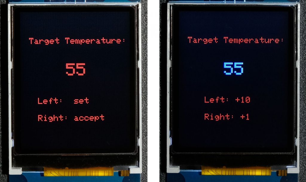
Setting the target temperature
When you start the sketch, you can set a target temperature. This is done by the function setTargetTemperature(). The sketch waits until you either accept the default setting of 55 °C or you choose “set”. If you choose the latter, the font color of the temperature changes. Use the left button to increase the set temperature by 10 degrees, and the right button to increase it by 1 degree. The tens jump to the four after the nine, the ones jump to the zero after the nine. This means you can set target temperatures from 40 to 99 °C. After four seconds without pressing a button, the temperature is set.
Coordinate cross
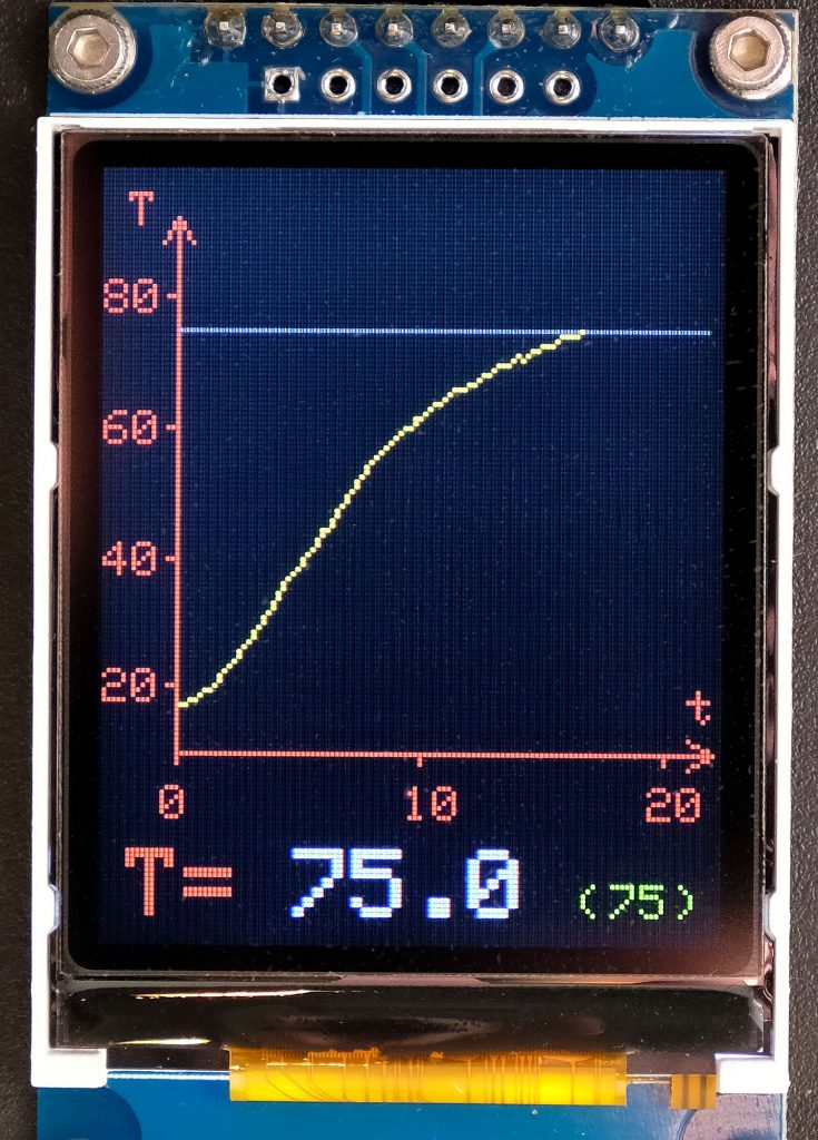
The origin (0,0) of the TFT display is at the top left. So, you have to rethink. The temperature-time coordinate cross has its origin at (0 min, 10 °C) = (CC_X_BEGIN, CC_Y_END) = (15, 120). Actually, units belong to the axes. Because of the limited space, I did without it.
The temperature axis is fixed, the time axis changes over time its resolution. At the beginning, each x-pixel corresponds to six seconds (secsPerXPixel). Therefore, 100 pixels equal 600 seconds = 10 minutes. After 10 minutes, every second value is simply deleted and the x-axis is “rescaled” to 0 to 20 minutes. The next change of scale is then made after 20 min (to 0 to 40 minutes), etc. The temperature axis ranges from 10 to 100 °C (upper edge of the display). 120 pixels are available for this. The resolution is therefore 1.3 pixels per degree.
The target temperature is displayed in green color at the bottom right and also visible as a blue line in the diagram. I have defined all the colors I use in the function myColor() and access them via an enum variable.
Timing
In waitForTemperatureUpdate(), the sketch is waiting for a new measured value of the transmitter unit, which is received every ~2.5 seconds or 3 seconds at “low battery”. The function returns the temperature as a float. After a period of secsPerXPixel ( = 6, 12, 24 … seconds), the measured value is converted into a coordinate point and displayed. After the one hundredth measured value, the scale of the time axis is doubled and the measured value counter is reset to 50.
Because the receiver waits up to 3 seconds for a new measured value, the time between two displayed measured values does not equal exactly secsPerXPixel. However, prevUpdate += secsPerXPixel ensures that any deviation is compensated for after the next measured value.
If the measured value reaches or exceeds the target temperature, the acoustic alert is triggered. By pressing the left button, the alarm is switched off. As the timing of the sketch is sequential, you have to press for up to 3 seconds. If this bothers you, you can control the deactivation of the alarm via an interrupt.
Construction of the receiver unit
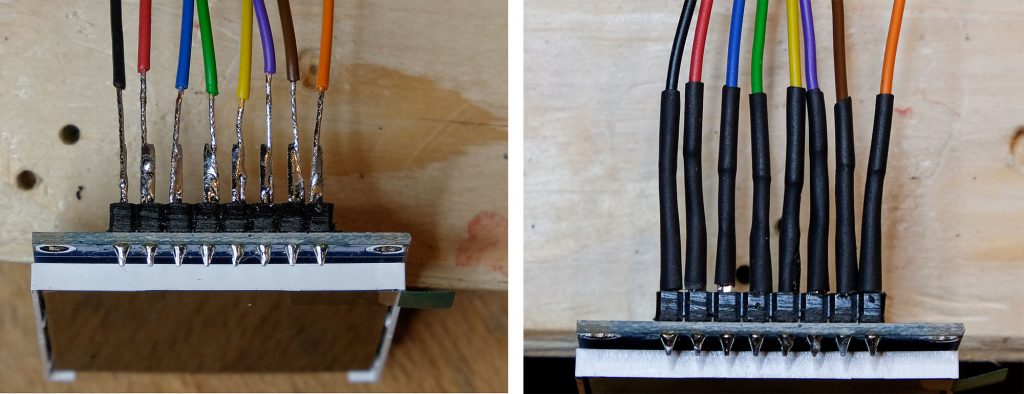
The concept of the housing, the circuit board and the battery is similar to that of the transmitter unit. Due to the many pins of the display and the level shifter, the soldering was quite time-consuming.

To connect the display, I soldered cables to the pins and protected the solder joints with heat shrink tubing.
And this is the output on the serial monitor:
Wireless BBQ Thermometer – Improvement Potential / Variants
There are many options to modify this project, for example:
- Reduce by:
- smaller housings (e.g. using a 3D printer), and
- customized boards.
- Connections for additional temperature sensors.
- Selection of the target temperature from a list, e.B. “Beef, medium: 57 °C”.
- Use of a 3.3 Volt MCU to get rid of the levelshifter.
- Omit the display on the transmitter unit.
- Use low-power MCUs, apply sleep modes.
- Embellishment by screwing on the displays from the inside.
Above all, the high level of craftsmanship will probably deter one or the other from this project. That’s why I will build a much simpler variant and report on it in the next post as a sequel:
- Transmitter unit without display and based on an ESP32.
- Transmission via WiFi.
- Using a smartphone/browser as a receiver.
Acknowledgement
I owe the picture of the steaks on the grill, which is the basis for my post picture, to David Butler on Pixabay.