
About this Post
In the last post, I introduced the ADS1220 24-bit, 4-channel A/D converter and my associated library. In this sequel, I will show you how to use the ADS1220 to take advantage of its benefits with practical examples.
I use the examples in the data sheet as a guide. To focus on the essentials, I have simplified the circuits. Most importantly, I left out all the RC filters, which can be a bit confusing for beginners. Even without them, I have achieved excellent results. However, if you want to reduce noise and interference even further, it’s worth taking a look at the data sheet.
Let’s take a look at the following applications:
Controlling thermocouples (type K) with the ADS1220
How does a thermocouple work?
In a nutshell: Thermocouples consist of two wires made from different metals connected at one of their ends. If there is a temperature difference along the wires, you can measure a voltage between the free ends. This is the Seebeck effect. Different metal pairings have different temperature-voltage characteristics. However, they have in common that they are almost linear over a wide range. Basically, the effect, i.e. the voltage change per degree, is small.
You can find temperature-voltage tables for the different thermocouples in many places on the net. The reference temperature is always 0° C. A disadvantage of thermocouples is that you can only measure temperature differences. The temperature at the point where you measure the voltage must be known.
Very widespread is the type K, which consists of the pairing nickel/nickel-chromium. With it, the voltage change is about 40 microvolts per degree, or about 4 millivolts per 100 °C. That’s not really much. And that’s why we need a high-resolution, low-noise, high-gain ADC here. This is an ideal challenge for the ADS1220.
The circuit on the ADS1220
We remember (and if not, check the last post): For the reliable operation of the PGA, i.e. the amplifier of the ADS1220, the output voltage of the PGA must be at least 200 millivolts above AVSS and at most 200 millivolts below AVDD. So, you must not perform “single-ended” measurements against AVSS. At least not if you want to apply a gain greater than 4.
Ideally, you work with input voltages that are close to (AVSS+AVDD)/2. You can achieve this with the following circuit:
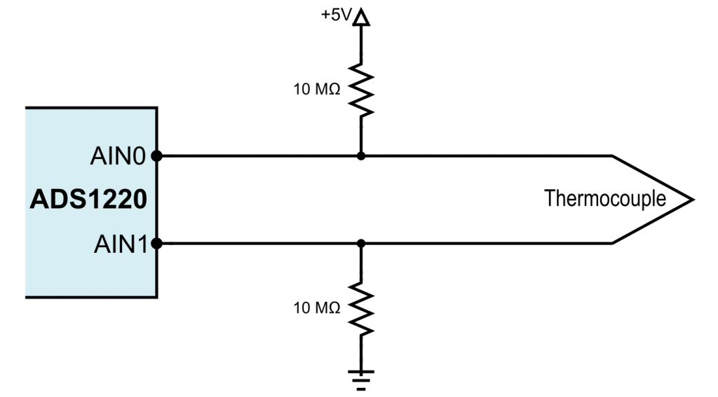
The two 10 megohm resistors force the voltage to be in the middle range. Their size prevents larger currents from flowing across the thermocouple and distorting the result. The ADS1220 data sheet recommends resistor values between 1 and 50 megohms.
The voltage of 5 volts is chosen arbitrarily. You can also, for example, apply 3.3 volts. And instead of the AIN0 and AIN1 inputs, the other inputs would be equally suitable.
Here is the complete circuit as a Fritzing scheme:
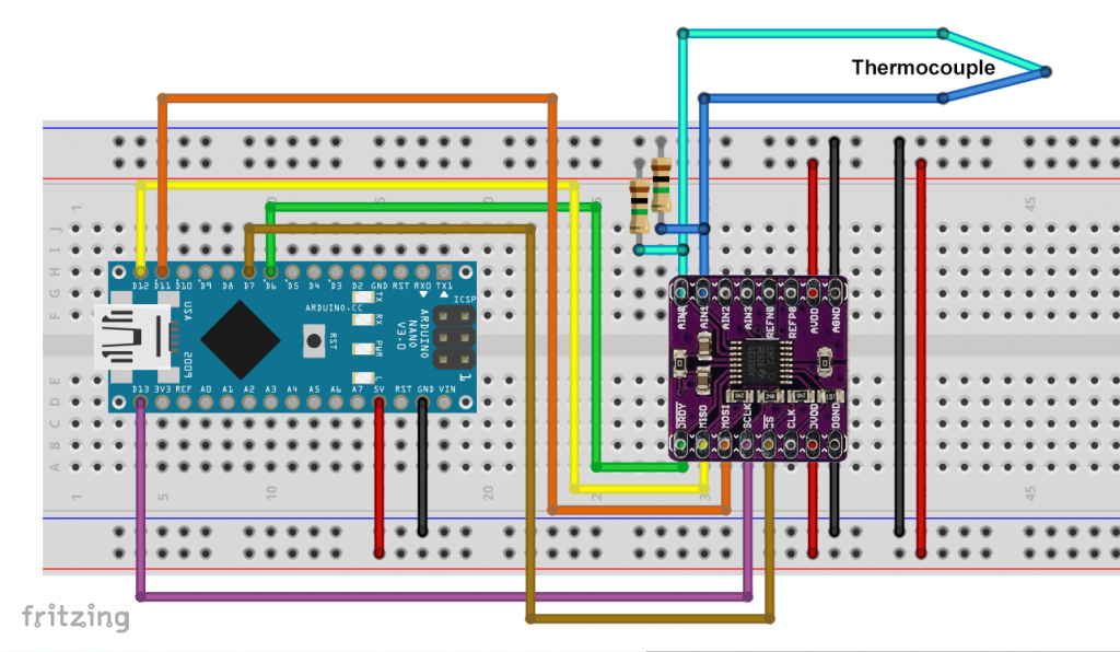
Do you notice that there are 1 megohm resistors shown here? The simple reason is that I have not found any 10 megohm resistors at Fritzing! However, 10 megohm resistors were actually used.
Regression lines and polynomials for the characteristic curves
In the following, we will measure thermoelectric voltages and calculate the temperature from them. For this purpose, I copied the thermoelectric voltage / temperature values for the thermocouple K into Excel and calculated regression functions (trendlines) from them. I limited myself to the range between -20 and +110 °C. The regression curves are only valid for this area.


As you can see, the linear approach is not bad for this relatively small temperature range. However, the square function on the right fits even better. If you want to cover larger temperature ranges, you should at least work with a quadratic function. I’m trying both here.
Linear approach
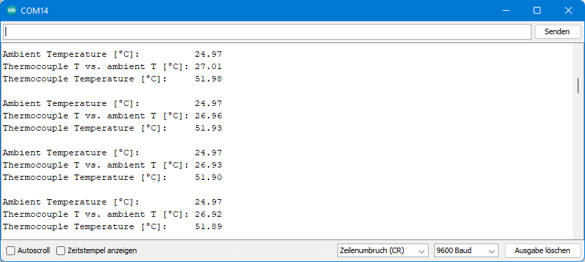
The linear approach is simple. You measure the ambient temperature with the internal thermometer of the ADS1220 or another temperature sensor. From the measured voltage, the sketch calculates the temperature difference and adds it to the ambient temperature.
Since the expected voltages are only a few millivolts, we can safely apply a gain of 128 and use the internal voltage reference (+/- 2.048 volts).
#include <ADS1220_WE.h>
#include <SPI.h>

#define ADS1220_CS_PIN    7 // chip select pin
#define ADS1220_DRDY_PIN  6 // data ready pin

ADS1220_WE ads = ADS1220_WE(ADS1220_CS_PIN, ADS1220_DRDY_PIN);

void setup(){
  Serial.begin(9600);
  if(!ads.init()){
    Serial.println("ADS1220 is not connected!");
    while(1);
  }
  ads.setCompareChannels(ADS1220_MUX_0_1);
  ads.setGain(ADS1220_GAIN_128);
}

void loop(){
  float ambTemp = 0.0;
  float deltaTemp = 0.0; // thermocouple temperature minus ambient temperature
  float tCTemp = 0.0; // thermocouple temperature
  float tCV = 0.0; // thermocouple voltage

  ads.enableTemperatureSensor(true);
  ambTemp = ads.getTemperature();
  ads.enableTemperatureSensor(false);
  Serial.print("Ambient Temperature [°C]:          ");
  Serial.println(ambTemp);

  tCV = ads.getVoltage_muV(); // get result in millivolts
  deltaTemp = 0.0244821*tCV + 0.106873;
  Serial.print("Thermocouple T vs. ambient T [°C]: ");
  Serial.println(deltaTemp);

  tCTemp = ambTemp + deltaTemp;
  Serial.print("Thermocouple Temperature [°C]:     ");
  Serial.println(tCTemp);
  Serial.println();

  delay(2000);
}
For the following output, I put the thermocouple in a cup of warm water. You can see nicely how the water cools down. A reference thermometer with a guaranteed maximum deviation of 0.2 °C was used for verification. The values determined with the thermocouple deviated from this by only a few tenths of a degree.
Polynomial approach
With the polynomial method, things are a little more complicated because we have to consider that the characteristic curve is referred to 0 °C. We measure the ambient temperature again with the ADS1220, but first calculate the thermoelectric voltage referred to 0 °C from it. To do this, we need another polynomial regression curve with the axes reversed (x = temperature, y = thermoelectric voltage). I’m not showing these curves here. We add this calculated voltage (voltage correction “vC”) to the measured thermoelectric voltage and insert the result into the polynomial regression curve.
This is the sketch:
#include <ADS1220_WE.h>
#include <SPI.h>

#define ADS1220_CS_PIN    7 // chip select pin
#define ADS1220_DRDY_PIN  6 // data ready pin

ADS1220_WE ads = ADS1220_WE(ADS1220_CS_PIN, ADS1220_DRDY_PIN);

void setup(){
  Serial.begin(9600);
  if(!ads.init()){
    Serial.println("ADS1220 is not connected!");
    while(1);
  }
  ads.setCompareChannels(ADS1220_MUX_0_1);
  ads.setGain(ADS1220_GAIN_128);
}

void loop(){
  float ambTemp = 0.0;
  float tCTemp = 0.0; // thermocouple temperature
  float tCV = 0.0; // thermocouple voltage
  float vC = 0.0; // voltage correction (deviation from 0°C)

  ads.enableTemperatureSensor(true);
  ambTemp = ads.getTemperature();
  ads.enableTemperatureSensor(false);
  Serial.print("Ambient Temperature [°C]:        ");
  Serial.println(ambTemp);

  vC = 1.16946*pow(ambTemp,2)*pow(10,-2) + 39.8013*ambTemp + 2.5078;
  Serial.print("Voltage Compensation [µV]:       ");
  Serial.println(vC);

  tCV = ads.getVoltage_muV(); // get result in millivolts
  Serial.print("Thermocouple Voltage [µV]:       ");
  Serial.println(tCV);
  tCV += vC;
  Serial.print("Corr. Thermocouple Voltage [µV]: ");
  Serial.println(tCV);

  tCTemp = -1.71627*pow(tCV,2)*pow(10,-7) + 2.51112*pow(10,-2)*tCV - 0.0664632;
  Serial.print("Thermocouple Temperature [°C]:   ");
  Serial.println(tCTemp);
  Serial.println();

  delay(2000);
}
And this is what the output looked like on my end:
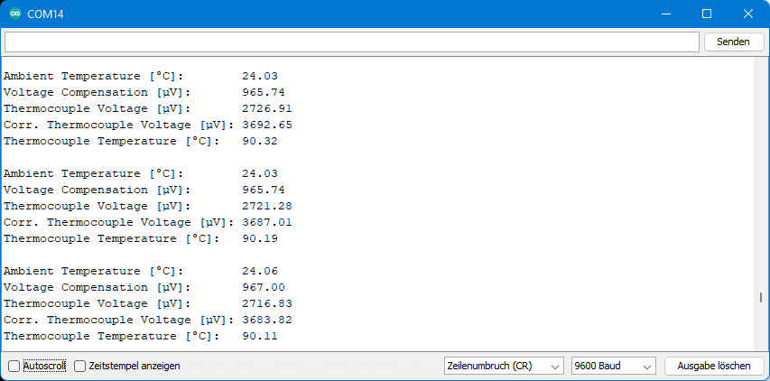
Again, a cup of hot water was used for this test.
resistance thermometer
Unlike thermocouples, which provide a temperature-dependent voltage, resistance thermometers change their resistance with temperature. The advantage is that you can determine temperatures absolutely, i.e. without a reference temperature.
The family of resistance thermometers consists of NTCs and the RTDs. NTC stands for “Negative Temperature Coefficient Thermistor”. That is, the resistance decreases with temperature. In German, NTCs are also referred to as hot conductors (“Heißleiter”). NTCs are characterized by comparatively high resistance values because they are made of metal oxides.
RTD stands for “Resistance Temperature Detector”. In this respect, one would assume that an NTC is also an RTD. However, only those thermometers whose resistance decreases with increasing temperature are called RTDs. These include the well-known “PT100” and “PT1000”. They are also referred to as PTCs or PTC thermistors. The number stands for the resistance at 0 °C, and the “PT” for the material used, namely platinum.
According to Ohm’s law, the resistance can be determined by a known current, and this can be provided by the ADS1220. Alternatively, you can also use a reference resistor which you connect in series with the resistance thermometer. But one by one.
Controlling NTCs (thermistors) with the ADS1220
Characteristic curve of the NTC
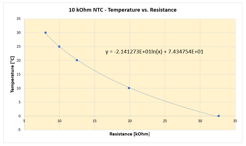
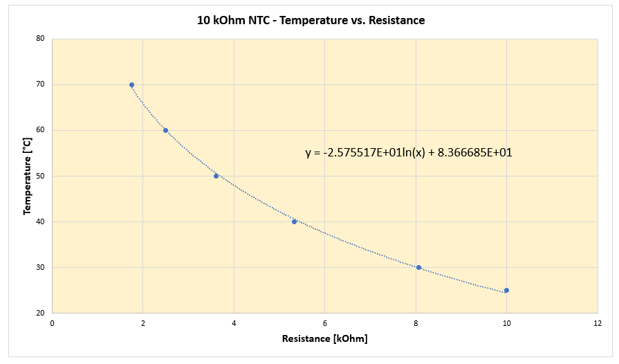
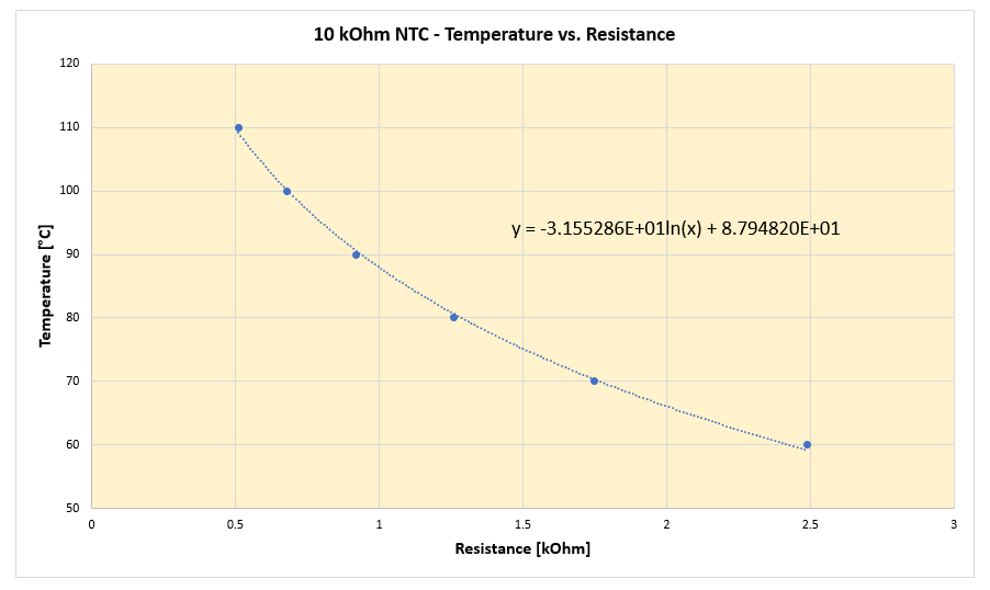
NTCs are classified according to their resistance value at 25 °C. For this article, I have chosen a 10 kiloohm model. Ideally, the manufacturers specify the so-called B-value, with which you can calculate the resistance R at a given temperature T compared to the reference temperature Tref:
![\[ R_{\text{T}}=R_{\text{T{ref}}}\cdot \text{e}^{B\cdot\left( \frac{1}{\text{T}}-\frac{1}{\text{T{ref}}}\right)} \]](https://wolles-elektronikkiste.de/wp-content/ql-cache/quicklatex.com-c9ce91bc222975cb45e352f792f76dc3_l3.png "Rendered by QuickLaTeX.com")
My 10 kΩ NTC did not have a B value specified, but it did have a table of values. I have tried various regression functions in Excel. For a satisfactory result, I had to divide the range of values into three parts. There are certainly better math programs that have more appropriate functions implemented. But Excel is accessible to almost everyone.
Measurement with the ADS1220
First of all, the method described here is not the most accurate. However, a few trial measurements showed deviations well below one degree. Besides, the method is simple. An error analysis still follows. It is better to use reference resistors. I will show this with the example of PTCs.
To measure the temperature dependent resistance, we use the IDAC function of the ADS1220. The measuring range I have chosen starts at 0 °C. At this temperature, the resistance is 32.69 kiloohm. At a current of 50 microamps, this results in a voltage of ~1.63 volts. This can still be measured well with the internal reference of the ADS1220, and the value is still well below the limit of AVDD – 0.9 volts. We must choose 1 as the gain factor.
The lowest resistance is ~0.5 kiloohm. With an IDAC of 50 microamperes, the voltage at the NTC is 25 millivolts. Since the gain factor is 1, this would also be the lower limit for the output voltage of the PGA. This is below the limit of AVSS + 200 millivolts. That’s why we need to bypass the PGA.
I used the following simple setup:

The sketch for this is also simple:
#include <ADS1220_WE.h>
#include <SPI.h>

#define ADS1220_CS_PIN    7 // chip select pin
#define ADS1220_DRDY_PIN  6 // data ready pin

ADS1220_WE ads = ADS1220_WE(ADS1220_CS_PIN, ADS1220_DRDY_PIN);

void setup(){
  Serial.begin(9600);
  if(!ads.init()){
    Serial.println("ADS1220 is not connected!");
    while(1);
  }

  ads.setCompareChannels(ADS1220_MUX_0_3);
  ads.setGain(ADS1220_GAIN_1);
  ads.bypassPGA(true); // true disables PGA, false enables PGA
  ads.setIdacCurrent(ADS1220_IDAC_50_MU_A);
  ads.setIdac1Routing(ADS1220_IDAC_AIN0_REFP1);
}

void loop(){
  float result = 0.0;
  float resistanceInKiloOhm = 0.0;
  float temperature = 0.0;

  result = ads.getVoltage_mV(); // get result in millivolts
  Serial.print("Voltage [mV]:      ");
  Serial.println(result,3);

  resistanceInKiloOhm = result / 50.0;
  Serial.print("Resistance [kOhm]: ");
  Serial.println(resistanceInKiloOhm,3);

  if(resistanceInKiloOhm > 9.0){
    temperature = -21.41273 * log(resistanceInKiloOhm) + 74.34754;
  }
  else if(resistanceInKiloOhm > 2.2){
    temperature = -25.75517 * log(resistanceInKiloOhm) + 83.366685;
  }
  else{
    temperature = -31.55286 * log(resistanceInKiloOhm) + 87.9482;
  }
  Serial.print("Temperature [°C]:  ");
  Serial.println(temperature);

  Serial.println();
  delay(2000);
}
And this is what the output looked like:
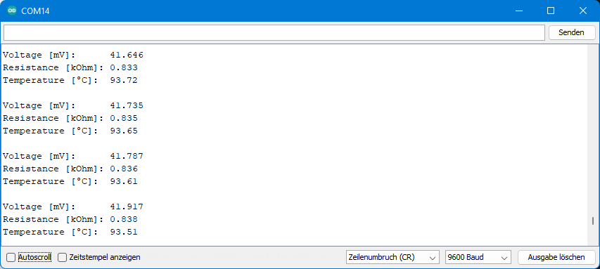
Error analysis
The data sheet specifies a typical deviation of +/- 1% for the IDAC. This error has a proportional effect on the determined resistance value. At 25 °C the resistance is 10 kΩ. What if we were to determine only 9.9 kΩ? When used in the regression function, this would result in a temperature of ~25.26 °C. The error is smaller than some might have thought. This is where the non-linear shape of the characteristic curve is beneficial.
However, the data sheet specifies +/- 6% as the maximum deviation of the IDAC. At 9.4 kΩ the temperature would be 26.37 °C. However, I am unable to say how likely it is that these maximum deviations of the IDAC actually occur.
The error of the reference voltage also has a directly proportional effect on the result. The data sheet specifies arange of 2,045 – 2,051 volts. This corresponds to about +/- 0.15%, so it is a rather small error.
In addition, there is an error caused by the lead resistance. At 25 °C (= 10 kΩ NTC resistance) this does not matter much. At 150 °C, however, the resistance is only 180 ohms according to the manufacturer’s table. Therefore, a long lead could influence the result.
Controlling RTDs (PTC thermistors) with the ADS1220
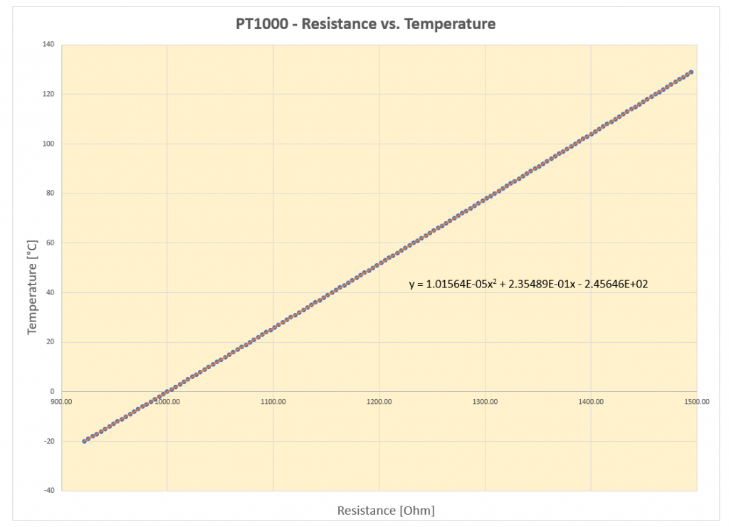
PT1000
The PT1000 has an almost linear characteristic curve. However, to match the resistance/temperature values even better, I chose a quadratic compensation curve:
Direct measurement with the ADS1220
First, I proceeded as I did with the NTC. This is not really recommended for PT1000, but I want to show the difference.
For the temperature range I considered, the resistance of the PT100 is ~1.5 kΩ maximum. That is why we can choose a higher IDAC current and gain in this case. However, the PGA must still be bypassed. With an IDAC of 250 µA, a gain of 4 and a maximum resistance of 1.5 kΩ, the maximum voltage (after amplification) is 1.5 volts, so the internal reference can be used.
#include <ADS1220_WE.h>
#include <SPI.h>

#define ADS1220_CS_PIN    7 // chip select pin
#define ADS1220_DRDY_PIN  6 // data ready pin

ADS1220_WE ads = ADS1220_WE(ADS1220_CS_PIN, ADS1220_DRDY_PIN);

void setup(){
  Serial.begin(9600);
  if(!ads.init()){
    Serial.println("ADS1220 is not connected!");
    while(1);
  }

  ads.setCompareChannels(ADS1220_MUX_0_3);
  ads.setGain(ADS1220_GAIN_4);
  ads.bypassPGA(true); // true disables PGA, false enables PGA
  ads.setIdacCurrent(ADS1220_IDAC_250_MU_A);
  ads.setIdac1Routing(ADS1220_IDAC_AIN0_REFP1);
}

void loop(){
  float result = 0.0;
  float resistanceInOhm = 0.0;
  float temperature = 0.0;
  float ambTemp = 0.0;

  ads.enableTemperatureSensor(true);
  ambTemp = ads.getTemperature();
  ads.enableTemperatureSensor(false);
  Serial.print("Ambient Temperature [°C]: ");
  Serial.println(ambTemp);

  result = ads.getVoltage_mV(); // get result in millivolts
  Serial.print("Voltage [mV]:             ");
  Serial.println(result,3);

  resistanceInOhm = result / 0.25;
  Serial.print("Resistance [kOhm]:        ");
  Serial.println(resistanceInOhm);

  temperature = 1.01564*pow(10,-5)*pow(resistanceInOhm,2) + 0.235489*resistanceInOhm - 245.646;
  Serial.print("Temperature [°C]:         ");
  Serial.println(temperature);

  Serial.println();
  delay(2000);
}
And here is the output. I measured against the internal temperature sensor of the ADS1220 for comparison.

Error analysis
Due to the almost linear shape of the characteristic curve, errors in the IDAC are much more noticeable than in the NTC. A deviation of only one percent results in a deviation of 2.6 °C. With this in mind, my readings above are already pretty good.
Measurement with the ADS1220 via a reference resistor
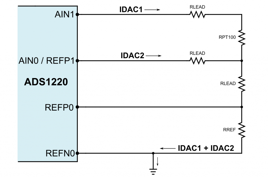
To eliminate the dependence on deviations of the IDAC, we let the current flow through a reference resistor after passing through the RTD and take this voltage as the reference voltage:

According to Ohm’s law
![\[ \frac{U_{\text{RTD}}}{R_{\text{RTD}}} = I_{\text{IDAC1}} = \frac{U_{\text{RRef}}}{R_{\text{RRef}}} \]](https://wolles-elektronikkiste.de/wp-content/ql-cache/quicklatex.com-de45f5cbc933eb11fef2505c9e323b2e_l3.png "Rendered by QuickLaTeX.com")
![\[ \Longrightarrow\;\;\;\; R_{\text{RTD}}=R_{\text{RRef}}\cdot \frac{U_{\text{RTD}}}{U_{\text{RRef}}} \]](https://wolles-elektronikkiste.de/wp-content/ql-cache/quicklatex.com-6d095a16d4af3d0e2518ad241f96de07_l3.png "Rendered by QuickLaTeX.com")
The reference voltage must be at least as large as the voltage to be measured. This means that the reference resistance must be at least as large as the largest resistance of RTD. I designed my circuit for RTD values up to 1.5 kΩ and chose an appropriate resistor. A measurement with my multimeter showed a value of 1.483 kΩ.
With an IDAC of 1 mA and a total resistance of ~3 kΩ, the maximum voltage at AIN1 is 3 volts. If you use a supply voltage (AVDD) of 5 volts, that is far below the limit of AVDD minus 0.9 volts. If you use lower supply voltages, like 3.3 volts, then you have to reduce the IDAC accordingly.
In the following sketch, REFP0/REFN0 is set as the equivalent voltage. The exact value we specify for the equivalent voltage does not matter. The determined voltage at the RTD is proportional to this setting. And since we divide the voltages to determine RRTD according to the above equations, the factor is eliminated. If this confuses you, you can alternatively work with the raw data (getRawData()) instead of the voltages.
The PGA does not need to be bypassed, since we are not getting close to the lower limit of AVSS plus 0.2 volts.
#include <ADS1220_WE.h>
#include <SPI.h>

#define ADS1220_CS_PIN    7 // chip select pin
#define ADS1220_DRDY_PIN  6 // data ready pin
#define VREF 2.0 // Reference Voltage, value does not matter

ADS1220_WE ads = ADS1220_WE(ADS1220_CS_PIN, ADS1220_DRDY_PIN);

void setup(){
  Serial.begin(9600);
  if(!ads.init()){
    Serial.println("ADS1220 is not connected!");
    while(1);
  }

  ads.setCompareChannels(ADS1220_MUX_1_0);
  ads.setGain(ADS1220_GAIN_1);
  ads.setVRefSource(ADS1220_VREF_REFP0_REFN0);
  ads.setVRefValue_V(VREF);  // exact value doesn't matter!
  ads.setIdacCurrent(ADS1220_IDAC_1000_MU_A);
  ads.setIdac1Routing(ADS1220_IDAC_AIN1);
} // end of setup()

void loop(){
  float result = 0.0;
  float resistanceInOhm = 0.0;
  float temperature = 0.0;
  float ambTemp = 0.0;

  ads.enableTemperatureSensor(true);
  ambTemp = ads.getTemperature();
  ads.enableTemperatureSensor(false);
  Serial.print("Ambient Temperature [°C]: ");
  Serial.println(ambTemp);

  ads.setCompareChannels(ADS1220_MUX_REFPX_REFNX_4);
  result = ads.getVoltage_mV();
  Serial.print("Reference Voltage [mV]:   ");
  Serial.println(result * 4.0);

  ads.setCompareChannels(ADS1220_MUX_1_0);
  result = ads.getVoltage_mV(); // get result in millivolts
  resistanceInOhm = result * 1.483 / VREF;
  Serial.print("Resistance [Ohm]:         ");
  Serial.println(resistanceInOhm);
  temperature = 1.01564*pow(10,-5)*pow(resistanceInOhm,2) + 0.235489*resistanceInOhm - 245.646;
  Serial.print("Temperature [°C]:         ");
  Serial.println(temperature);

  Serial.println();
  delay(2000);
}
And this is what my output looked like:
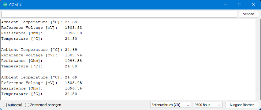
The temperatures determined with the PT1000 are in excellent match with those of the internal thermometer (“Ambient Temperature”). And both, in turn, did not deviate by more than two or three tenths of a degree from my high-precision reference thermometer in various measurements.
By the way, the output of the reference voltage is only used to check if things work as calculated. The value is not used any further. Theoretically, the reference voltage should be 1.483 volts. Perhaps the typical 1% deviation of IDAC comes into play here. Furthermore, according to the data sheet, the measurement of the external reference is not a precision measurement.
PT100
The measuring principle: 3-wire and 4-wire
The resistance of the PT100 at 0 °C is only 100 Ohm. This causes another error to become more relevant, namely the line resistance RLEAD. To compensate for the error, there are 3-wire or 4-wire PT100 (and PT1000!). The 3-wire PT100 has a double wire leading into it. With the 4-wire PT100, on the other hand, both lines are doubled. The double leads are each short-circuited before the sensor. Suitable circuits can be used to compensate for the lead influence.
3-wire circuit
The following circuit can be applied to the 3-wire PT100:
To calculate the voltages AIN1 and AIN0, we just need to multiply the currents by the sum of the resistors through which they flow. The voltage difference between AIN1 and AIN0 is:
![\[ U_{\text{AIN1-AIN0}} = I_{\text{IDAC1}}\cdot \left(2\cdot R_{\text{LEAD}} +R_{\text{PT100}} + R_{\text{REF}} \right) - I_{\text{IDAC2}}\cdot \left(2\cdot R_{\text{LEAD}} + R_{\text{REF}} \right) \]](https://wolles-elektronikkiste.de/wp-content/ql-cache/quicklatex.com-7e005fe24dc818903468214877019855_l3.png "Rendered by QuickLaTeX.com")
Since IDAC1 is equal to IDAC2, and we assume that the lead resistance values are all equal, after eliminating the brackets:
![\[ U_{\text{AIN1-AIN0}} = I_{\text{IDAC}}\cdot R_{\text{PT100}} \]](https://wolles-elektronikkiste.de/wp-content/ql-cache/quicklatex.com-5a68d5927bb0c3d4aba426cd84123025_l3.png "Rendered by QuickLaTeX.com")
This eliminates the resistance of the leads.
For the reference voltage applies:
![\[ U_{\text{REF}} = 2\cdot I_{\text{IDAC}}\cdot R_{\text{REF}} \]](https://wolles-elektronikkiste.de/wp-content/ql-cache/quicklatex.com-b073c0d2e9458861f3c05f2dda2cbe8e_l3.png "Rendered by QuickLaTeX.com")
If you divide the last two equations by each other and solve for RPT100, you get the following simple formula:
![\[ R_{\text{PT100}} = 2\cdot\frac{U_{\text{AIN1-AIN0}}}{U_{\text{REF}}}\cdot R_{\text{REF}} \]](https://wolles-elektronikkiste.de/wp-content/ql-cache/quicklatex.com-9164567706d4209c521cdbd8ff0b146e_l3.png "Rendered by QuickLaTeX.com")
RREF is known, we can measure the voltages, and a balancing polynomial was again used to convert RPT100 to temperature:
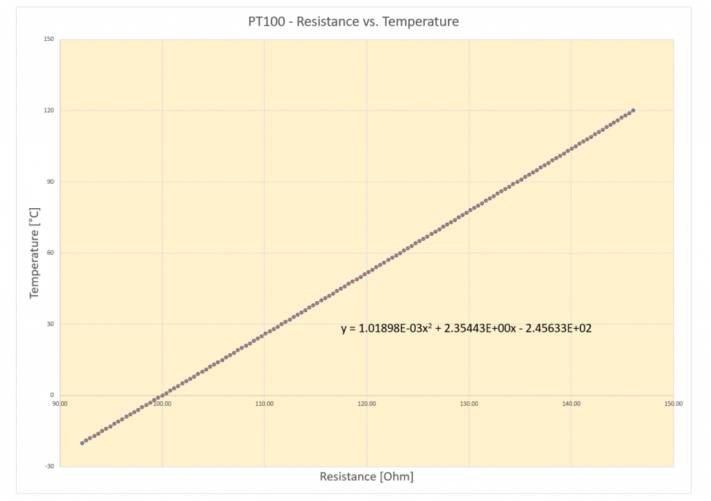
As reference, I have chosen a 2.4 kΩ resistor (exactly: 2.403 kΩ). IDAC1 and IDAC2 were 500 microamperes each. Thus, the reference voltage is about 2.4 volts. In the temperature range I considered, the PT100 resistance is greater than 90 Ω and less than 150 Ω. UAIN1-AIN0 is thus between 90 Ω x 500 µA and 150 Ω x 500 µA, i.e. between 45 mV and 75 mV. With a gain factor of 32, the limits of the PGA output voltage are thus 1.44 V and 2.4 V. All good!
Sketch and output
#include <ADS1220_WE.h>
#include <SPI.h>

#define ADS1220_CS_PIN    7 // chip select pin
#define ADS1220_DRDY_PIN  6 // data ready pin
#define VREF 2.0 // Reference Voltage, value does not matter

ADS1220_WE ads = ADS1220_WE(ADS1220_CS_PIN, ADS1220_DRDY_PIN);

void setup(){
  Serial.begin(9600);
  if(!ads.init()){
    Serial.println("ADS1220 is not connected!");
    while(1);
  }

  ads.setCompareChannels(ADS1220_MUX_1_0);
  ads.setGain(ADS1220_GAIN_32);
  ads.setVRefSource(ADS1220_VREF_REFP0_REFN0);
  ads.setVRefValue_V(VREF);  // value doesn't matter, the ratio is important
  ads.setIdacCurrent(ADS1220_IDAC_500_MU_A);
  ads.setIdac1Routing(ADS1220_IDAC_AIN1);
  ads.setIdac2Routing(ADS1220_IDAC_AIN0_REFP1);
} // end of setup()

void loop(){
  float result = 0.0;
  float pt100ResistanceInOhm = 0.0;
  float leadResistanceInOhm = 0.0;
  float temperature = 0.0;
  float ambTemp = 0.0;

  ads.enableTemperatureSensor(true);
  ambTemp = ads.getTemperature();
  ads.enableTemperatureSensor(false);
  Serial.print("Ambient Temperature [°C]: ");
  Serial.println(ambTemp);

  ads.setCompareChannels(ADS1220_MUX_REFPX_REFNX_4);
  result = ads.getVoltage_mV();
  Serial.print("Reference Voltage [mV]:   ");
  Serial.println(result * 4.0);

  ads.setCompareChannels(ADS1220_MUX_1_0);
  result = ads.getVoltage_mV(); // get result in millivolts
  pt100ResistanceInOhm = result * 2.0 * 2.403 / VREF; // Reference resistor: 2.403 kOhm
  Serial.print("Resistance PT100 [Ohm]:   ");
  Serial.println(pt100ResistanceInOhm);

  temperature = 1.01898*pow(10,-3)*pow(pt100ResistanceInOhm,2) + 2.35443*pt100ResistanceInOhm - 245.633;
  Serial.print("Temperature [°C]:         ");
  Serial.println(temperature);

  Serial.println();
  delay(2000);
}
And here is the output:
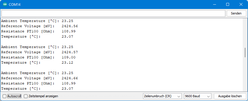
The temperature values determined with the PT100 matched well the measurements of the ADS1220’s internal thermometer (“Ambient Temperature”) and my precise reference thermometer.
Again, the reference voltage is a little bit higher than expected. But as with the previous example, it doesn’t matter as long as the error is IDAC-related. I should mention, however, that although IDAC1 and IDAC2 can deviate from the target by up to 6 percent according to the data sheet, the difference between IDAC1 and IDAC2 is a maximum of 0.3 percent. Only this makes the measurement sufficiently accurate.
And one more note: If you try this example yourself by testing this on a breadboard and connecting the PT100 with alligator clips, be aware that you will create significant unwanted resistance. If your determined PT100 resistance deviates by only one ohm, this results in a temperature deviation of three degrees! The PT1000 is much less sensitive in this respect.
4-wire circuit
4-wire RTDs are even more accurate. The following circuit eliminates the influence of the leads:

The calculation is even simpler because we use only one IDAC.
![\[ U_{\text{AIN1-AIN0}} = I_{\text{IDAC}} \cdot R_{\text{PT100}} \]](https://wolles-elektronikkiste.de/wp-content/ql-cache/quicklatex.com-39f0303c7a1adbca4b14913ebbb42fc2_l3.png "Rendered by QuickLaTeX.com")
![\[ U_{\text{REF}} = I_{\text{IDAC}}\cdot R_{\text{REF}} \]](https://wolles-elektronikkiste.de/wp-content/ql-cache/quicklatex.com-cff08395e101ceddd1d003a9926f7ce5_l3.png "Rendered by QuickLaTeX.com")
![\[ R_{\text{PT100}} =\frac{U_{\text{AIN1-AIN0}}}{U_{\text{REF}}}\cdot R_{\text{REF}} \]](https://wolles-elektronikkiste.de/wp-content/ql-cache/quicklatex.com-e151b2cdc8f9a3a034a06cec0a106462_l3.png "Rendered by QuickLaTeX.com")
For example, at 5 volts supply voltage, you could choose a 4.7 kΩ resistor as RREF and 500 microamps as IDAC. You should now be able to create a sketch for this yourself. Since I had no 4-wire PTC available, I have not tried the circuit.
Wheatstone bridges with the ADS1220
As a final application example, let’s look at Wheatstone bridge circuits. These are used to determine small resistances or small resistance differences, e.g. when using strain gauges. Maybe you have already worked with it without knowing it. Many load cells are based on Wheatstone bridges of strain gauges. But I won’t go into the theory here, because that would take us too far.
The circuit is very simple:

The supply voltage of the bridge is also the reference voltage. The output voltage of the bridge is measured as the difference between two inputs of the ADS1220. The cool thing is that the output voltage is proportional to the input voltage and therefore also to the reference voltage. Fluctuations in the supply voltage therefore do not play a role.
And this is where the Low Side Switch comes into play. If you activate the function, the low side switch closes during a measurement. Otherwise, it is open and thus prevents the bridge from consuming power unnecessarily.
For testing, I dug out my bending plate with Wheatstone bridge from the post on strain gauges again:
The associated sketch is simple:
#include <ADS1220_WE.h>
#include <SPI.h>

#define ADS1220_CS_PIN    7 // chip select pin
#define ADS1220_DRDY_PIN  6 // data ready pin

/* Create your ADS1220 object */
ADS1220_WE ads = ADS1220_WE(ADS1220_CS_PIN, ADS1220_DRDY_PIN);

void setup() {
  Serial.begin(9600);
  if (!ads.init()) {
    Serial.println("ADS1220 is not connected!");
    while (1);
  }

  ads.setCompareChannels(ADS1220_MUX_1_2);
  ads.setGain(ADS1220_GAIN_128);
  ads.setVRefSource(ADS1220_VREF_REFP1_REFN1);
  ads.setVRefValue_V(5.0);  // The exact value doesn't matter!
//  ads.setRefp1Refn1AsVrefAndCalibrate(); // That will not work here!!
  ads.setLowSidePowerSwitch(ADS1220_SWITCH);
}

void loop() {
  float result = 0.0;
  result = ads.getVoltage_mV(); // get result in millivolts
  Serial.print("Bridge Voltage [mV]: ");
  Serial.println(result, 3);

  delay(2000);
}
In this case, the gain can be set to 128 because the output voltage of the bridge is only a few millivolts. The PGA does not need to be bypassed as there is no danger of approaching AVDD or AVSS to 200 millivolts.
This is what the output looked like when I pressed down on the bending plate and then let it relax again:
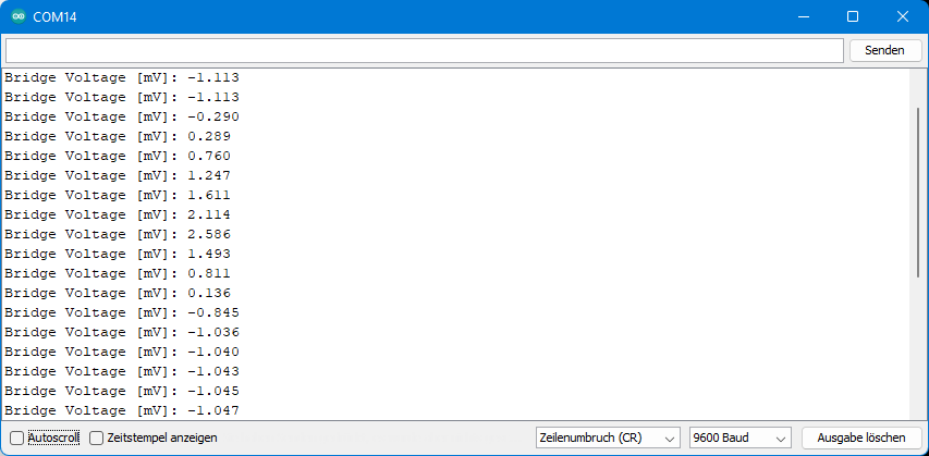
I tried reducing the bridge voltage from 5 volts to 3.3 volts without changing the sketch. The measured values did not change. Of course, the output voltages are then no longer correct. But they don’t have to, since values stand for certain strains or (weight) forces. And these should be independent of fluctuations in bridge voltage.
If this bothers or confuses you, then you might as well work with the raw values (via getRawData()) instead of the voltages.
Hi Wolfgang,
Am I right in thinking, that I can use two NTC sensors with one ADS1220?
Eg. AIN0 – NTC_1 – AIN3, AIN1 – NTC_2 – AIN2?
Regards
Tamás Mohos
Hi Tamas,
yes, I see no reason why it shouldn’t work. Good luck! A feedback after you tried it is much appreciated.
Regards, Wolfgang
Hi Wolfgang,
thanks for the fast ansver. I am now using ADS1220 for 4-20mA sensors and it works well. I will report back once I have tried the 2 NTCs.
Hi Wolfgang,
I’m curious about your last example with the Wheatstone bridge. The code references ads.setVRefSource(ADS1220_VREF_REFP1_REFN1); but those aren’t broken out on the board. REFP0 and REFN0 are.
I’m having stability issues, so I’m just trying to understand what works and what doesn’t.
My mistake. They are just labeled differently.
Hi Ben,
AIN0 and REFP1 share one pin and AIN3 and REFN1 share one pin. You find this information in the first part of this article or in the pinout scheme in the data sheet (page 4).
Hi Wolfgang,
Thank you so much for sharing a great library! I have a question: can your library operate the ADS1220 with only three lines by using DOUT/DRDY shared mode, and tying CS to ground?
Will your library work in the DOUT/DRDY mode if I set drdy to true:
void ADS1220_WE::setDrdyMode(ads1220DrdyMode true) and pass the SPI DOUT pin as drdy? Also, I am looking to tie the CS pin to ground, and pass an unused pin as CS. Is there a reason this wouldn’t work?
Hi Igor,
the correct call of setDrdyMode() in order to receive the data ready signal on both DRDY and DRDY/DOUT (MISO) would be setDrdyMode(ADS1220_DOUT_DRDY);. I have not tried myself if SPI works correctly then. Maybe just try yourself? And yes, as long as you don’t have another SPI device on the same SPI connections pulling CS to LOW should work.
Hi Wolfgang,
Thank you very much for sharing this useful work. I am trying to measure a load cell with a Wheatstone bridge, when I try the code at the end of the article I get the desired result.
I need to read 2 load cells with an ads1220.
ads.setCompareChannels(ADS1220_MUX_1_2);
when I change this line to
ads.setCompareChannels(ADS1220_MUX_0_1);
I can make the code work between inputs 0 and 1. However, when I change it to
ads.setCompareChannels(ADS1220_MUX_2_3);
and connect inputs to 2 and 3, it does not work. I checked if there are any errors in the library and saw that you coded everything according to the datasheet. Do you have any ideas about this?
Best regards
Alp Erkan ŞAVLI
Hi Alp,
so the only thing you changed was the ads.setCompareChannel() from ADS1220_MUX_1_2 to ADS1220_MUX_0_1 or ADS1220_MUX_2_3 (and the connections to the ADS1220 of course)? Spontaneously, I have no idea why it does not work. I am a bit too busy to try it myself this week, maybe on the weekend.
What does “it does not work” mean exactly? Do you always get the same result or arbitrary results?
Regards, Wolfgang
Hi again,
When i use ADS1220_MUX_2_3, it always return Bridge Voltage [mV]: 39.062
Hi,
I think I have the answer: try a lower PGAIN. 39.062 x 128 = 4.999,936 which is practically 5 Volts which means you are exceeding the reference voltage.
Regards, Wolfgang
Hello Wolfgang,
Thank you for your answers. I found the problem. It’s about the command below.
ads.setLowSidePowerSwitch(ADS1220_SWITCH);
I read this part of the datasheet:
Low side power switch configuration
This bit configures the behavior of the low side switch connected to the vehicle.
AIN3/REFN1 and AVSS.
0 : Switch is always on (default)
1: When the START/SYNC command is sent, the switch automatically closes and
It turns on when the POWERDOWN command is given.
then I recognize ads.setLowSidePowerSwitch(ADS1220_SWITCH); to order
I replace it with ads.setLowSidePowerSwitch(ADS1220_ALWAYS_OPEN)
it works perfectly now. Thanks again.
Best regards, Alp
Hallo Wolfgang, dies ist einfach wunderbar!
Thank you so much for this article it’s super useful. I have an application measuring type S and type K thermocouples and I opted for the ESP32, because with SPIFFS file system I have the possibility of using a look up table approach. I just downloaded the tables from here: https://srdata.nist.gov/its90/main/ and with a Python script cleaned the .txt files a bit before uploading them to ESP32. When I have everything working I think I should publish this to github and with your permission, it would be great to use theADS1220 library for getting the voltages.
One thing that I am confused though is the cold junction compensation. In your linear approach, you just added the ambient temperature to the deltaTemp but in the polynomial approach you got a voltage compensation from the ambient temperature, added that to thermocouple voltage and the total voltage was then translated to temperature. I am wondering if with my look up table approach I will need to also find the compensation voltage first, add that to the measured voltage, and finally translate just the total compensated voltage from the table… previously I was just adding the ambient temperature to the thermocouple temperature.
Grußi!
Pablo
Hi Pablo,
I would say if the ambient temperature is not too high or low, you can still just add the ambient temperature. The further you move away, the higher the influence of the non-linearity. I would just try and check if the results make sense.
Greetings from Germany, Wolfgang
Hi Wolfgang,
I finally had the time to test everything and the correct way to do it is to compensate the measured voltage with the cold junction voltage. I just had to write some functions that either lookup voltage based on temperature (for the cold junction) or lookup temperature based on voltage (for the real thermocouple temperature using corrected voltage). For lower temperature applications I think the non-linearity error of just adding the ambient temperature shouldn’t be too critical.
On another note, the way the ADS1220 inputs are pulled up with the bias resistors (the 10Mohm ones), I should be able to detect an open/broke thermocouple. Quoting Texas Instruments:
“Additionally, in this application if a thermocouple is disconnected these resistors will automatically drive both inputs to supply and ground giving an obvious sensor disconnect condition to an ADC.”
So in theory the ADC should read a full-scale value, outside the normal measurement range of the thermocouple voltage, to indicate this failure condition. However when I disconnect my thermocouple I get a measurement of 16.00mV which is actually very well inside the normal measurement range.
I had to prototype everything, including SMD components in a little perfboard so perhaps my issue is there. On the code side of things, I do this:
// setup…
ads.setCompareChannels(ADS1220_MUX_0_1);
ads.setGain(ADS1220_GAIN_128);
…
// loop
V_TC = ads.getVoltage_mV(); // get result in millivolts
Serial.printf(“Differential voltage: %.2f mV\n”, V_TC);
Hi Wolfgang,
I really learned a lot from your ADS1220 articles. I’m currently using it to record geophone data for a second or two at a time, lots of data! I also regularly use an ADS1115 to control a glass kiln for art work. Noticed in your article you didn’t mention the US Bureau of Standards polynomial thermocouple equations. I use the Type K polynomial. A snippet from my code is:
amb = ads.getTemperature() * 1.8 +32; //Getting temperature of the internal sensor
l = ads.getVoltage_mV()/1000; //equation needs volts, not millivolts
temp = .226584602 + l * (24152.109 + l * (67233.4248 + l * (2410340.682 + l * (-860963914.9 + l * (4.83506e10 + l * (-1.18452e12 + l * (1.3869e13 – 6.33708e13 * l)))))));
temp = (temp * 1.8) + amb; //Celsius to Fahrenheit conversion
At first I didn’t totally trust the results I got because they differed from the PID controller I had used before, but once I used some pure metal melt tests in the kiln to confirm the accuracy of the equation, I was convinced the PID controller was not correct. A pure zinc sample melted within a few degrees of the published value. In the 700 +F range the PID controller was reading 30 degrees F high.
Many thanks,
George
Hi George,
many thanks for this. The US Bureau of Standards website is very helpful. I didn’t know that yet.
I have taken a look at this page:
https://srdata.nist.gov/its90/type_k/kcoefficients_inverse.html
According to that page, the equation would be:
t90 = d0 + d1E + d2E^2 + … dnE^n
where dx are the coefficients that are listed there and E is the voltage in millivolts.
What I don’t find there is exactly the equation that you applied. Can you tell me where I can find it?
Greetings from Germany, Wolfgang
Hi Wolfgang,
I found the polynomial coefficients in Omega Engineering Temperature Handbook, 1989, page Z-14 which references an NBS publication from 1979. I have seen and tried the later coefficients which were divided into temperature ranges which you found. Honestly, for the work I was doing (art glass fusing), the all in one formula which covers the entire temperature range from the Omega Engineering 1989 handbook was enough for me. For my work I’m mainly interested in accurate temperature readings between 1250 – 1500 F. A 30 F error can produce a very different end result. Interesting to note I tried the Maxim MAX31855 chip and found it to be off by about 70 F at higher temperatures (it was quite accurate at room temp).
On a separate note, I have experienced some unwanted oscillations (feedback?) on my ADC inputs at high sampling rates. My sampling can go on just fine for a while with the usual minor noise and then all of a sudden, high amplitude noise/oscillations just swamp out the normal signal. Tried by-pass caps on the input with no success. I would imagine you know the exact cause. I have noticed the problem is more acute with longer lead lengths to my geophone. I suspect I may be seeing ringing between the ADC and the geophone magnet/coil combo.
Any help would be appreciated Jedi Master.
Hi George,
calling me Jedi Master makes it hard for me to say that I don’t know what could cause the oscillations. I guess you have read the section 9.2.1 in the data sheet about the K-type thermocouple measurements and followed the recommendations. I can also imagine that the issue is somehow related to the geophone. If it is the radiation, then maybe just simple shielding with aluminium foil could help. What might also help is stabilizing the power supply. But, to be honest, I begin to guess here. If I think of a good idea overnight, I will share it.
Dear Wolfgang Ewald
Many thanks for the work you have done on ADS1220. I have tried out the ADS1220 with the Wheatstone bridge configuration of strain gauges and getting improved results. How can the value of the ADS 1220 be read and stored to SD card given that both are using the SPI interface?. The the micro-controller being used is the ESP32.
In addition, the measurement interval is quite small (about 10 milliseconds).
Paul Okoth
Hi Paul,
SPI devices connected to one microcontroller share the same MISO, MOSI and SCK lines. You just need individual CS (“Chip Select”) pins and lines. That’s all. Alternatively you can use the two SPI interfaces of the ESP32, if the library you are using allows to pass SPI objects. It would lead too far here to explain the details. If you are interested you may read this:
https://wolles-elektronikkiste.de/en/programming-the-esp32-with-arduino-code#SPI
To achieve a high read / write speed the SPI clock rate should be set as high as possible if the libraries you use allow that. In my lib for the ADS1220 you can set the clock rate with setSPIClockSpeed(). I am not sure about the limit – just try. On the ADS1220 you can apply high data rates and the turbo mode – but the higher the rate the higher the noise.
Hope this helps!
Wolfgang
Hi Wolfgang Ewald
I tried and finally managed to get the two SPI devices working. Many thanks for the information. The first try failed, the ESP devkit kept resetting. This was caused by using default GPIO 12 (HSPI_MISO) for the second device. To solve this an alternative pin was used instead. This can help anyone who tries and gets the issue. Was able to get up to time interval of 1 millisecond!
Another observation is made when using NTP (network time, gettimeofday() function) to record timestamps for the purpose of synchronization. The WiFi is on and when it updates the time the ADC is picking interference (Radio Frequency) this can be seen as outlier spikes in the data. When using network time I got a minimum of 8 milliseconds. Is it possible to stretch this to 1 millisecond?
Finally is there an ADC that has higher sampling rate than ADS1220 say greater than 10ksp that can be used with MCU?
Regards
Paul Okoth
Hi Paul,
the ADS1255 and ADS1256 have a maximum sample rate of 30 ksps:
https://www.ti.com/lit/ds/symlink/ads1256.pdf?ts=1681810280346&ref_url=https%253A%252F%252Fwww.ti.com%252Fproduct%252FADS1256
There are libraries available on GitHub:
https://github.com/ADS1xxx-Series-ADC-Libraries/ADS1255-ADS1256
I have not tried them.
If you want a time stamp you could use a DS3231 RTC module, the you don’t need WiFi. Or, alternatively, you could use a “soft RTC” which based on the millis() function:
https://github.com/adafruit/RTClib/blob/master/examples/softrtc/softrtc.ino
The accuracy is not the best, but you could adjust the time regularly.
Regards, Wolfgang