About this post
Some time ago, I had reported about programming ATtiny MCUs using the ATTinyCore package (link to the post). However, ATtinyCore covers only a part of the ATtiny family. The representatives of the tinyAVR® series 0, 1 and 2, which Microchip has launched in recent years, are missing. They differ fundamentally in some aspects from the other members of the ATtiny family. You can program these newer ATtinys with Arduino code using the megaTinyCore package from Spence Konde.
Probably the most considerable difference in dealing with these newer microcontrollers is programming via UPDI (Unified Program and Debug Interface). This is a proprietary programming and debug interface from Microchip that requires only a single wire. I present several options for uploading sketches via UPDI using the Arduino IDE. This is what you can expect:
- The megaTinyCore family
- Preparations
- Uploading sketches with megaTinyCore – 3 options
- Uploading sketches via Optiboot bootloader
- Using the Serial Monitor without Optiboot
- Outlook
The megaTinyCore family
The megaTinyCore family is quite large. Here is first an overview which covers some selected features:

The name of the ATtinys reveals a few of their properties:
- From the first or the first two digits you can derive the size of the program memory in kilobytes.
- The penultimate digit indicates the tinyAVR series.
- The last digit will tell you the number of pins:
- ATtinyxx7: 24 pins
- ATtinyxx6: 20 pins
- ATtinyxx4: 14 pins
- ATtinyxx2: 8 pins
See the megaTinyCore documentation here on GitHub for more detailed information about the series and subgroups, including pinout schemes.
However, the subject of this article is mainly the programming about the use of megaTinyCore and less the technical data.
Preparations
Acquisition of the microcontrollers
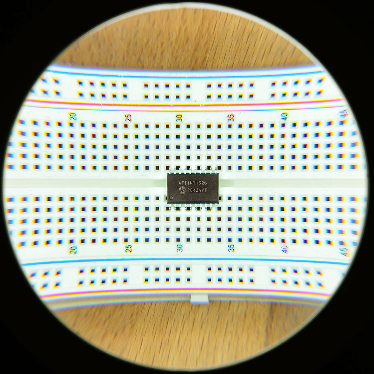
The availability of tinyAVR series 0, 1 and 2 representatives is currently limited. In some cases there are long delivery times. I found some of the tinyAVR MCUs mainly on eBay, with a wide price range. For this article, I tried the ATtiny1614, ATtiny1626 and ATtiny3226. Not because I find these three particularly attractive, but because they are the ones I could get at a reasonable price.
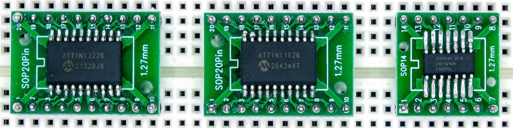
The tinyAVRs of the series 0, 1 and 2 are not available as PDIP, i.e. you cannot plug them directly into a breadboard. Fortunately, there are adapter PCB boards available. On the net, you can find many instructions how to solder SOIC (1.27 mm pin spacing) or SSOP components (0.65 mm pin spacing).
If you don’t like this fine work you can buy development boards in the Tindie Shop, here for example the ATtiny3224/1614/1604 versions. However, the store is located in the USA. The shipping costs of approx. 16 US$ are correspondingly high. I have not seen such boards elsewhere, but that I expect this to change eventually.
Preparation of the Arduino IDE for megaTinyCore
First you have to implement megaTinyCore in the Arduino IDE. To do this, go to File → Preferences. Click on the icon behind “Additional Boards Manager URLs” and enter “https://descartes.net/package_drazzy.com_index.json” in a separate line (the original board manager URL that you find in the installation instructions on GitHub does not work anymore!)
Close the windows by clicking “OK”.
Now navigate to Tools → Board → Boards Manager. Search for the megaTinyCore package from Spence Konde and install it:

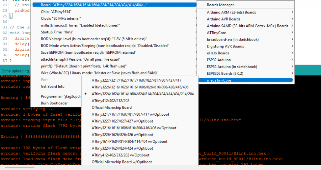
If everything worked out, you will find a large selection of ATtinys in your Arduino IDE:
Uploading sketches with megaTinyCore – 3 options
Programming via UPDI requires suitable programmers. Unfortunately, there is not yet much choice for “off the shelf” models. The good news, however, is that you can make do with inexpensive components.
Option 1: The Arduino as UPDI Programmer
Preparing the Arduino
First, we turn an Arduino UNO or Arduino Nano into a UPDI programmer. I guess it also works with other Arduino boards, but I haven’t tried that. The following steps must be performed:
- Get jtag2udpi here from GitHub. To do this, follow the link, click on the green button “Code” and then on “Download ZIP”.
- Save the ZIP file somewhere on your computer and unzip it.
- In the folder jtag2updi-master you will find the subfolder source, which you rename to jtag2updi.
- Move the folder jtag2updi into your Arduino Sketch folder. You can now delete the zip file and the folder jtag2updi-master.
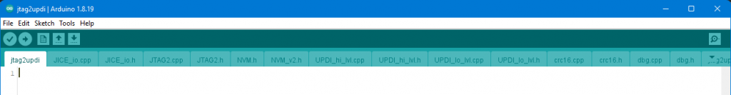
- Open the file jtag2updi.ino, which you can find in the folder jtag2updi, with the Arduino IDE. The sketch itself is empty (see below), but the relevant files are in the same folder and are processed automatically.
- Upload the sketch to your Arduino. Of course, you have to set the Arduino of your choice as board.
Now your Arduino is ready to be used as UPDI programmer.
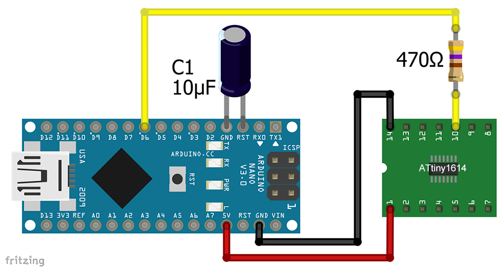
Wiring
Connecting ATtinys to your new UPDI programmer is easy. Connect GND to GND and VCC to VCC. Place a 10 µF capacitor between GND and reset of the Arduino. Connect the Arduino pin 6 via a 470 kΩ resistor to the UPDI pin of the ATtiny. At jtag2updi on GitHub a 4.7 kΩ resistor is applied. That also worked for me.
For the ATtiny1614 used here, the UPDI pin is pin 10. You can find out the UPDI pin of your ATtiny in the datasheet, or just have a look at the pinout schemes on GitHub. Follow this link and click on the group which contains your ATtiny.
For convenience: Here you find a nice idea how to convert the Arduino Nano to a ready-to-use UPDI programmer.
Upload
Select the ATtiny in the Arduino IDE under Tools → Board → megaTinyCore. There are versions with and one without Optiboot bootloader. Take the one without Optiboot. If you know what you’re doing, you can make all sorts of fine adjustments. If not, then use the default settings.
Set jtag2updi as programmer. Now you can upload sketches to your ATtiny. To try it out, I usually take a blink sketch.
Option 2: USB-to-TTL adapter as UPDI programmer
The second option I want to present uses a USB-to-TTL adapter as a UPDI programmer. You can get such a device for a few euros in online stores like Amazon or AliExpress. Most of these adapters have an FTDI FT232 or a CH340 chip. Spence Konde recommends the models with the CH340 chip. Check here if you want to know more about this topic. I tried the non-recommended version with FT232 chip and it worked perfectly fine right away. In addition, I could not reproduce the speed problems described by Spence Konde.
If you want to use the Optiboot bootloader (below), then I recommend a USB-to-TTL adapter with DTR pin.
The wiring is also not particularly complicated. All you need is a Schottky diode and a 470 Ω resistor. I have found different specifications for the diode. Partly Schottky diodes were used, but partly also “normal” diodes.
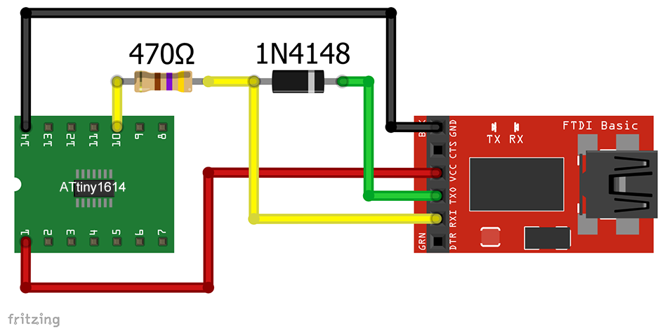
So, it does not necessarily have to be the 1N4148 diode shown here. For me, it also worked with the Schottky diode SB360, which is oversized for this purpose. Alternatively, to the diode you can use a resistor. I successfully tried with 4.7 kΩ. However, depending on the adapter you use, there may also be a few pitfalls. I recommend: Try it first and if there are problems, see what Spence Konde writes about these issues here.
As a programmer, you choose one of the SerialUPDI options. Test which speed (baud rate) works for you.
Here on GitHub, you can find a design for a nice little UPDI programmer. I have found a commercially available SerialUPDI programmer so far only here.
Option 3: Atmel-ICE as UPDI programmer
By far the simplest, but also most expensive variant is programming with the ATATMEL-ICE (short: Atmel-ICE). Depending on the configuration, you will have to pay between 100 and 200 Euros. But for this, you get a good programmer, which can handle UPDI, JTAG, ISP, debugWIRE and some more protocols.
If you use the Atmel-ICE as UPDI programmer, then three of its connector pins remain unused. The UPDI pin is where the MISO pin is normally assigned.
Connect VCC to VCC, GND to GND and UPDI to UPDI. However, VCC of the Atmel ICE does not provide a supply voltage, but is only used to check whether the voltage level is sufficient. Hence, you still need a separate voltage source.
Then choose the Atmel-ICE as programmer and upload your sketches. It’s as simple as that.
Update Dec 23: further UPDI programmers are available
Meanwhile there are mor UPDI programmers available. I have bought the EXA-PROG from Diamex and it works fine. In addition to UPDI, it also masters a range of other programming methods. It costs ~ 30 Euros (Dec 23).

I found another programmer, the microUPDProgrammer from MCUdude, here on Tindie-Shop. It is even cheaper but limited to UPDI.
Uploading sketches via Optiboot bootloader
As an alternative to UPDI you can also upload your sketches to the megaTinyCore MCUs via RX/TX using the Optiboot bootloader. For this, you use a USB-to-serial adapter again. The advantage is that the adapter can serve both as a programming device and as a connection to the serial monitor. The disadvantage of this method is the memory space needed by the bootloader (approx. 500 bytes) and possibly a delay during the boot process (see below).
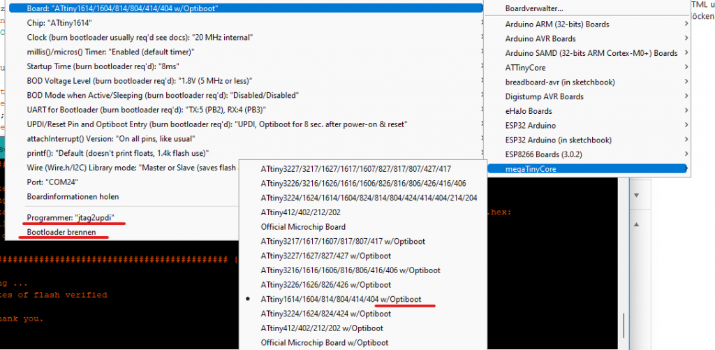
But first you have to burn the Optiboot bootloader (just once) via UPDI. There is no way around this step. To do this, go to Tools → Board and select the desired ATtiny with “w/Optiboot” and the UPDI Programmer. If your ATtiny has several UART interfaces, then you can set which of them should be used for Optiboot.
Optiboot without reset pin – for all tinyAVR series
This is how the setting for an ATtiny1614 might look like:
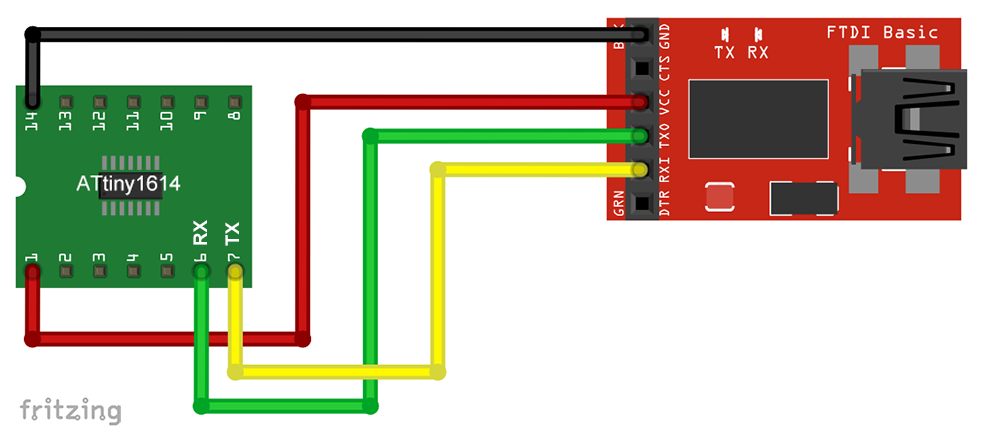
After you have burned the bootloader, you remove the UPDI programmer and connect the USB-to-serial adapter. For this, you connect RX of the adapter with TX of the ATtiny and TX of the adapter with RX of the ATtiny. You can find the pinout schematics on GitHub as part of the megaTinyCore library if you are not sure about the pins.
Choose the port for the adapter and upload the first sketch. If you want to upload another sketch later, you will have to power on the ATtiny only eight seconds before. This is the period the ATtiny waits during its boot process for sketches to be uploaded. Unfortunately, you will have to wait the same amount of time for your sketches to start.
If the eight seconds should annoy you, you can also limit the time to one second. This setting must be selected when burning the bootloader:

However, with a delay of only one second, it is somewhat of a challenge to supply power to the ATtiny at the right moment.
Be aware: The other two setting options disable UPDI. I.e. you can no longer change settings for which you have to burn the bootloader. Only a high-voltage UPDI programmer could reverse this.
Optiboot with reset pin – only for tinyAVR 2 series
With the MCUs of the tinyAVR 2 series it is possible to set up an alternative reset pin and preserve the UDPI functionality. This allows convenient programming using the DTR pin of the USB-to-serial adapter. I show this with the example of the ATtiny1626. Note, however, that not every USB-to-serial adapter has such a DTR pin.
In the Arduino IDE, select your ATtiny in Tools → Boards. Again, take the variant with Optiboot. Then set the UPDI programmer of your choice. In Tools, you will find the menu item “UPDI/alt-RST pins and Optiboot Entry (…)”. There you select the following marked entry (example ATtiny 1626):
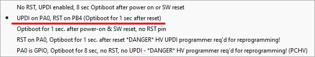
Now burn the bootloader with your UPDI programmer. The UPDI pin of the ATtiny1626 is pin 16 (GPIO17 / PA0).
Then connect your USB-to-serial adapter to the ATtiny. For the ATtiny1626, the circuit looks like this:
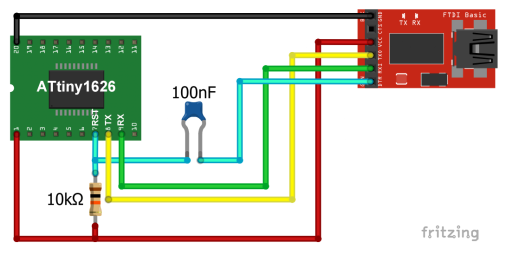
For other ATtinys, look into the pinout scheme to find the correct RST, TX and RX pin.
Select the port of the adapter and you can upload sketches without reconnecting or similar.
Using the Serial Monitor with megaTinyCore without Optiboot
You may not necessarily want to sacrifice approx. 500 bytes of flash memory for the bootloader, and still use the serial monitor. This is not a problem. To do this, connect your programmer and the USB-to-serial adapter to the ATtiny. At the adapter you only need to connect RX, TX and GND. Also connect VCC of the adapter if you want to use it as power supply.
If you use the Arduino or a USB-to-serial adapter as UPDI programmer and combine them with a USB-to-serial adapter for the serial connection, then two selectable ports appear under Tools → Port. When uploading, you must choose the port of the programmer and switch to the other port to use the serial monitor. When using an ATMEL-ICE, there is no problem because it does not show up as a serial port.
Outlook
In this post, I have only discussed the options of program upload with megaTinyCore. I have only mentioned the technical features and functions of the tinyAVRs in passing. In a later post, I will pick out one or two representatives and go into this aspect in more detail.
Acknowledgement
Only thanks to the package megaTinyCore it is possible to program the tinyAVRs of the series 0, 1 and 2 comfortably with the Arduino IDE.Spence Konde has done a fantastic job here, also regarding the documentation. Thank you very much!
Hi Wolfgang, I have to program some ATTinys and found you article above, Thanks for the work you put into this. Now I created the empty “jtapudpi.ino” file and copies in all the other files as you said. Also I set the board to AT Nano Every.However I get the following messages.
——————————————————————————–
Build options changed, rebuilding all
Warning: platform.txt from core ‘Arduino megaAVR Boards’ contains deprecated compiler.path={runtime.tools.avr-gcc.path}/bin/, automatically converted to compiler.path=/usr/bin/. Consider upgrading this core.
avr-g++: error: device-specs/specs-atmega4809: No such file or directory
exit status 1
Error compiling for board Arduino Nano Every.
———————————————————————–
I am using Arduino IDE 1.8.19 (still). Any hints,tips or obervations most welcome.
Thanks,
John
Hi John,
I think the issue is that you are using an Arduino Nano Every which is different from the Arduino Nano. The procedure was tested on the Arduino Nano and not on any Arduino Nano like the Arduino Nano Every, Arduino Nano 33 BLE, Arduino Nano ESP32 etc.
Regards, Wolfgang
Sketch uses 924 bytes (3%) of program storage space. Maximum is 30720 bytes.
Global variables use 9 bytes (0%) of dynamic memory, leaving 2039 bytes for local variables. Maximum is 2048 bytes.
avrdude: stk500_recv(): programmer is not responding
avrdude: stk500_getsync() attempt 1 of 10: not in sync: resp=0xab
avrdude: stk500_getsync() attempt 2 of 10: not in sync: resp=0xe0
avrdude: stk500_getsync() attempt 3 of 10: not in sync: resp=0xe0
avrdude: stk500_getsync() attempt 4 of 10: not in sync: resp=0xe0
avrdude: stk500_getsync() attempt 5 of 10: not in sync: resp=0x00
avrdude: stk500_getsync() attempt 6 of 10: not in sync: resp=0xe0
avrdude: stk500_getsync() attempt 7 of 10: not in sync: resp=0xe0
avrdude: stk500_getsync() attempt 8 of 10: not in sync: resp=0xe0
avrdude: stk500_getsync() attempt 9 of 10: not in sync: resp=0x00
avrdude: stk500_recv(): programmer is not responding
avrdude: stk500_getsync() attempt 10 of 10: not in sync: resp=0x00
Failed uploading: uploading error: exit status 1
Hi Rolf,
there are many potential reasons for getting this error. Wrong programmer chosen, an issue with the circuit, wrong board / chip chosen etc.
I am happy to look deeper into this issue if you provide further information about your circuit, the Attiny you are using, the programmer, settings etc. If you like, you can send me this information via e-mail. That is easier for attaching photos or screenshots.
e-mail address: Wolfgang.Ewald@wolles-elektronikkiste.de
Regards, Wolfgang