About this post
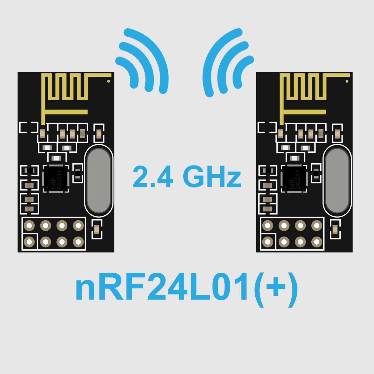
The nRF24L01 or nRF24L01+ is a powerful transceiver(transmitter andreceiver) for the 2.4 GHz ISM frequency band, which you can control using Arduino boards or other microcontrollers and the RF24 library. The library has good sample sketches, but they may be a bit hard to digest, especially for beginners. I wrote this post to – hopefully – make it a little easier to get started.
What topics I will cover:
- Technical features of the nRF24L01 modules
- Preparations (installation of the library, cabling)
- Minimal sketch for transmitter and receiver
- Advanced sketches
- The nRF24L01 as MultiCeiver™.
- Changing the role of the nRF24L01
- Extended Acknowledgements
- Using interrupts of the nRF24L01
- More functions
- Indoor range test
Technical features of the nRF24L01 modules
The nRFL01 series is a product of Nordic Semiconductors. A data sheet for the nRF24L01(+) is not or no longer available on the manufacturer’s website. Only a preliminary product specification seems to be in circulation as documentation, for example here on GitHub.
Most of you will use the nRFL24L01 ready mounted on a module, not the bare IC. Of these, there are many different designs. Especially widespread are these models:
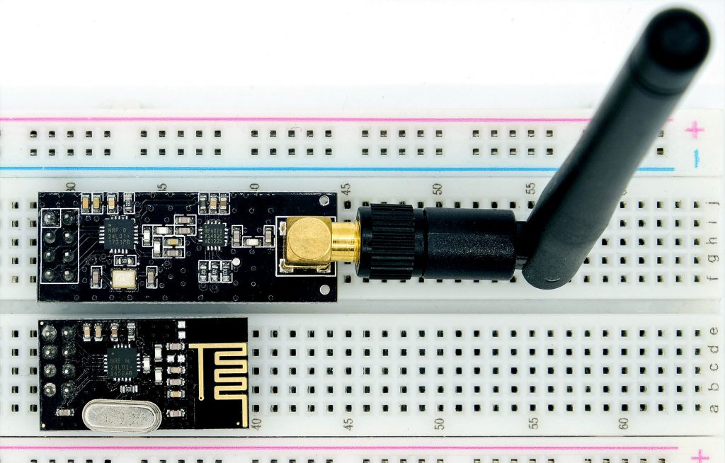
The upper, large module with SMA antenna is usually offered as “nRF24L01 + PA + LNA”, where PA stands for Power Amplifier and LNA for Low Noise Amplifier. It is said to achieve a range of up to 800 meters. In return, it consumes a whopping 115 milliamperes in transmit mode and up to 45 milliamperes as receiver.
The “nRF24L01 + PA + LNA” modules are sensitive to electromagnetic radiation. If they do not work, then try to shield them. A metal case would be ideal. It also works with a layer of aluminum foil, but then you have to put a layer of insulating material over it beforehand to avoid short circuits. See also here. For me, the parts actually worked only after shielding. I almost threw it in the garbage can until I found the hint with the shielding.
The small modules are less problematic. They need a maximum of around 14 milliamps. In return, their range is 100 meters (seller’s specification). More on that below. A combination of the different modules also works.
More technical data
- Operating voltage: 1.9 – 3.6 volts
- Voltage tolerance of the I/O pins: 5 volts
- Channels: 125 (2.400 – 2.525 GHz)
- Data rate: 250 kbit/s, 1 Mbit/s or 2 Mbit/s
- Max. Output power: 0 dBm
- Standby power consumption: 26 µA
- FIFO (First In, First OUT) buffer: 3 x 32 bit
- Communication: via SPI
Pinout / Connections
The nRF24L01 modules have 8 pins:
- MISO/MOSI/SCK: SPI connections
- GND/VCC: Power supply
- CE: Chip Enable
- CSN: Chip Select
- IRQ: Interrupt Pin
The pin arrangement and lack of labeling are somewhat inconvenient for experimental circuits. If you want to have it a bit more comfortable, you can get adapter boards for little money. In addition to reasonably labeled outputs, these have an AMS1117-3.3 voltage regulator and capacitors for voltage stabilization. This means that at least 4.6 volts are required for operation.
If you – like me – prefer to put the components firmly into the breadboard, you can alternatively use an ESP8266-ESP01 adapter. But then you have to remove the capacitor (ESD) and rename the outputs.

Preparations
Connection to the microcontroller
The following circuit was used for the example sketches:
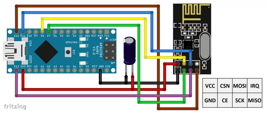
A 10 µF electrolytic capacitor was used. However, you can also choose a larger model.
Only for one sketch, I additionally connected the interrupt pin IRQ to the Arduino pin 2.
If you use a “nRF24L01 + PA + LNA” module, then the power supply via the 3.3 volt pin on the transmitter side might not be sufficient. The Arduino UNO and the Nano only supply up to 50 milliamps. For test operation over short distances, you can reduce the transmitting power. Otherwise, you should select a stronger power source.
Installing the RF24 Library
You can find the RF24 library via the library manager of the Arduino IDE. Search for “RF24”:
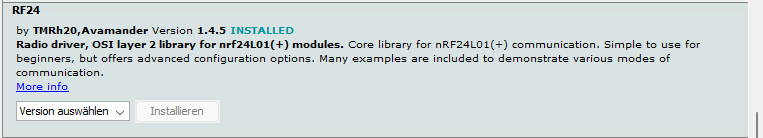
Alternatively, download the library from GitHub here.
Notes on the sketches
The RF24 library contains a number of example sketches demonstrating the functions of the nRF24L01. However, the examples can be a bit confusing at first glance because the authors have combined the transmitter and receiver parts into one sketch each. Only after the program start, the respective module is assigned its role via the serial monitor. This is actually pretty cool, but, as previously mentioned, it makes it a little harder to understand. I have therefore written separate sketches for the transmitter and the receiver.
Some of my example sketches produce output on the serial monitor on both the transmitter and receiver sides. You can, of course, switch back and forth between the ports, but it is easier to create two instances of the Arduino IDE. That is, you open the Arduino IDE twice, assign a separate port to each, and can open two serial monitors at the same time.
Minimal sketch
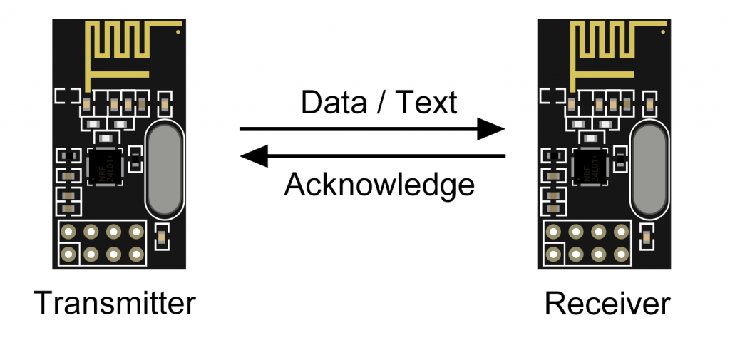
In the first example, two nRF24L01 modules are used. One takes the role of the sender, the other serves as the receiver. When the receiver receives a message, it sends an acknowledgement back to the transmitter. There is nothing of this in the first example, but I wanted to mention this aspect already here.
Minimum transmitter sketch
We start with the transmitter sketch:
#include <SPI.h>
#include <RF24.h>

RF24 radio(7, 8); // (CE, CSN)

const byte address[6] = "1RF24"; // address / identifier

void setup() {
  radio.begin();
  radio.openWritingPipe(address); // set the address
  radio.stopListening(); // set as transmitter
}
void loop() {
  const char text[] = "Hi Receiver"; // max. 32 bytes
  radio.write(&text, sizeof(text));

  delay(2000);
}
Explanations of the transmitter sketch – pipes and addresses
Be aware – now it might get a bit confusing: The data transmission of the nRF24L01 modules is handled via so-called pipes. This is a type of communication channel. However, the pipes are not to be confused with the “channels”, which we will get to later. The nRF24L01 has one pipe for writing (= sending). You can set up to six pipes for reading (= receiving).
For two nRF24L01 modules to be able to communicate with each other, the pipe of the sender (“writing pipe”) and the pipe – or one of the pipes – of the receiver (“reading pipe”) must have the same address. The address consists of 5 bytes. The designation “address” is perhaps a little misleading, but I did not want to deviate from the nomenclature of the library or the data sheet. You can also think of the address simply as an identifier. Take it that way for now. Later it will – hopefully – become clearer.
Further explanations of the transmitter sketch
You first include the necessary libraries and then use RF24 radio(7, 8) to create an RF24 object named “radio”. You also define the CE and CSN pins. Additionally, you could pass the SPI clock rate – see the documentation of the class here.
With radio.begin() the nRF24L01 module is initialized. With openWritingPipe(address) you open the writing channel and set the address. The function stopListening() puts the module into transmitter mode.
You send your messages in chunks of maximum 32 bytes. You define them as a character array and pass them to the function write(). To save memory, pass the character array as a reference. To do this, prefix the variable name with the address operator &.
Minimum receiver sketch
Let’s move on to the receiver sketch:
#include <SPI.h>
#include "RF24.h"

RF24 radio(7, 8); // (CE, CSN)

const byte address[6] = "1RF24"; // address / identifier

void setup() {
  Serial.begin(115200);
  radio.begin();
  radio.openReadingPipe(0,address); // set the address for pipe 0
  radio.startListening(); // set as receiver
}

void loop() {
  if(radio.available()){
    char text[33] = {0};
    radio.read(&text, sizeof(text)-1);
    Serial.println(text);
  }
}
The main differences from the transmitter sketch are:
openReadingPipe(0, address)opens the read channel 0 and sets the address. Since there is more than one reading channel, you need to specify it. The possible values are 0 to 5. For reasons that will become clear later, you might choose only 0 or 1 in this example.startListening()puts the nRF24L01 into receiver mode.available()checks whether a message has been received.read()reads the message. You must pass the variable which stores the message and the number of bytes to be read.- The variable
textis a character array. Character arrays end with the invisible null character'\0'. That is whytexthas a length of 33 and not 32.
- The variable
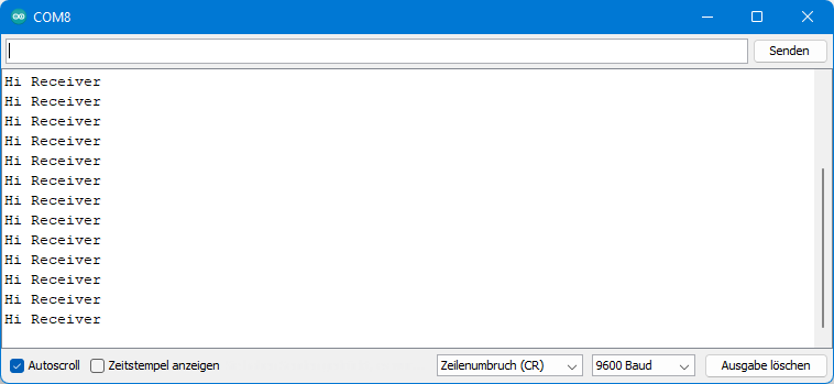
The receiver sketch output shouldn’t be a surprise to you:
Advanced sketches
The following two sketches basically do the same thing as the minimal sketches. Messages are sent from the transmitter to the receiver and output there. However, the sketches are extended by various functions. Some of these functions change the default settings, others provide more security.
Extended transmitter sketch
Here is the transmitter sketch first:
#include <SPI.h>
#include <RF24.h>

RF24 radio(7, 8); // (CE, CSN)

const byte address[6] = "1RF24"; // address / identifier

void setup() {
  Serial.begin(115200);
  if(!radio.begin()){
    Serial.println("nRF24L01 module not connected!");
    while(1){}
  }
  else
    Serial.println("nRF24L01 module connected!");

  /* Set the data rate:
   * RF24_250KBPS: 250 kbit per second
   * RF24_1MBPS:   1 megabit per second (default)
   * RF24_2MBPS:   2 megabit per second
   */
  radio.setDataRate(RF24_2MBPS);

  /* Set the power amplifier level rate:
   * RF24_PA_MIN:   -18 dBm
   * RF24_PA_LOW:   -12 dBm
   * RF24_PA_HIGH:   -6 dBm
   * RF24_PA_MAX:     0 dBm (default)
   */
  radio.setPALevel(RF24_PA_LOW); // sufficient for tests side by side

  /* Set the channel x with x = 0...125 => 2400 MHz + x MHz
   * Default: 76 => Frequency = 2476 MHz
   * use getChannel to query the channel
   */
  radio.setChannel(0);

  radio.openWritingPipe(address); // set the address
  radio.stopListening(); // set as transmitter

  /* You can choose if acknowlegdements shall be requested (true = default) or not (false) */
  radio.setAutoAck(true);

  /* with this you are able to choose if an acknowledgement is requested for
   * INDIVIDUAL messages.
   */
  radio.enableDynamicAck();

  /* setRetries(byte delay, byte count) sets the number of retries until the message is
   * successfully sent.
   * Delay time = 250 µs + delay * 250 µs. Default delay = 5 => 1500 µs. Max delay = 15.
   * Count: number of retries. Default = Max = 15.
   */
  radio.setRetries(5,15);

  /* The default payload size is 32. You can set a fixed payload size which must be the
   * same on both the transmitter (TX) and receiver (RX)side. Alternatively, you can use
   * dynamic payloads, which need to be enabled on RX and TX.
   */
  //radio.setPayloadSize(11);
  radio.enableDynamicPayloads();
}
void loop() {
  const char text[] = "Hi Receiver";
  Serial.println(sizeof(text));
  if(radio.write(&text, sizeof(text)-1, 0)){ // 0: acknowledgement request, 1: no ack request
    Serial.println("Message successfully sent");
  }
  delay(2000);
}
Some explanations:
begin()you already know. But here we check with the return value (true / false) if the nRF24L01 module is connected.- Use
setDataRate()to set the data transfer rate. There are three options to choose from: 250 kbit/s, 1 Mbit/s or 2 Mbit/s. Please note: Transmitter and receiver must have the same setting! setPALevel()determines the gain level. You can set -18, -12, -6 or 0 dBm. The larger the value, the greater the range. However, the same is true for power consumption.- The function
setChannel(channel)allows you to change the transmission frequency. The frequency is 2400 MHz + channel * 1 MHz with channel = 0 to 125. The transmitter and receiver must be set to the same frequency. Default is 76. - With
setAutoAck(true/false)you define whether the transmitter should request an acknowledgement or not. Default is “true”. enableDynamicAck()allows you to specify for each write() function individually whether an acknowledgement should be sent or not.- If an acknowledgement is requested but not received, the nRF24L01 resends the message. You control the number of repetitions (count) and the time between the repetitions (delay) with
setRetries(delay, count). Here delay is a number between 0 and 15 and the resulting delay is 250 µs + delay * 250 µs. The default setting issetRetries(5, 15). setPayloadSize(size)sets the length (size) of the message (the payload). Preset issize = 32. You must set the same value on the transmitter and receiver side.- Alternatively, keep the length of the message variable with
enableDynamicPayloads(). write()you already know, but:- With the parameter
sizeof(text)-1we pass the character array without the terminating null character. On the receiver side, we can attach it again. Of course, you can also pass the null string – but what for? - We pass a third parameter that controls whether an acknowledgement shall be sent. 0 is with, 1 is without acknowledgement. Exactly the other way around than one would expect!
- We use the return value of
write()to check if the data transfer was completed successfully. Of course, this only works if an acknowledgement is also requested.
- With the parameter
Extended receiver sketch
And here is the receiver sketch:
#include <SPI.h>
#include "RF24.h"

RF24 radio(7, 8); // (CE, CSN)

const byte address[6] = "1RF24"; // address / identifier
void setup() {
  Serial.begin(115200);
  if(!radio.begin()){
    Serial.println("nRF24L01 module not connected!");
    while(1){}
  }
  else
    Serial.println("nRF24L01 module connected!");

  /* Set the data rate:
   * RF24_250KBPS: 250 kbit per second
   * RF24_1MBPS:   1 megabit per second
   * RF24_2MBPS:   2 megabit per second
   */
  radio.setDataRate(RF24_2MBPS);

  /* Set the power amplifier level rate:
   * RF24_PA_MIN:   -18 dBm
   * RF24_PA_LOW:   -12 dBm
   * RF24_PA_HIGH:   -6 dBm
   * RF24_PA_MAX:     0 dBm (default)
   */
  radio.setPALevel(RF24_PA_LOW); // sufficient for tests side by side

   /* Set the channel x with x = 0...125 => 2400 MHz + x MHz
   * Default: 76 => Frequency = 2476 MHz
   * use getChannel to query the channel
   */
  radio.setChannel(0);

  radio.openReadingPipe(0,address); // set the address
  radio.startListening(); // set as receiver

  /* The default payload size is 32. You can set a fixed payload size which
   * must be the same on both the transmitter (TX) and receiver (RX)side.
   * Alternatively, you can use dynamic payloads, which need to be enabled
   * on RX and TX.
   */
  //radio.setPayloadSize(11);
  radio.enableDynamicPayloads();
}

void loop() {
  if(radio.available()){
    byte len = radio.getDynamicPayloadSize();
    Serial.println(len); //just for information
    char text[len+1] = {0};
    radio.read(&text, len);
    Serial.println(text);
  }
}
There is less to say about the receiver sketch:
- The settings for the payload must match those of the transmitter.
getDynamicPayloadSize()queries the size of the payload in bytes.- Since we passed the character array without a null character, we add it back by defining
char text[len+1] = {0}.
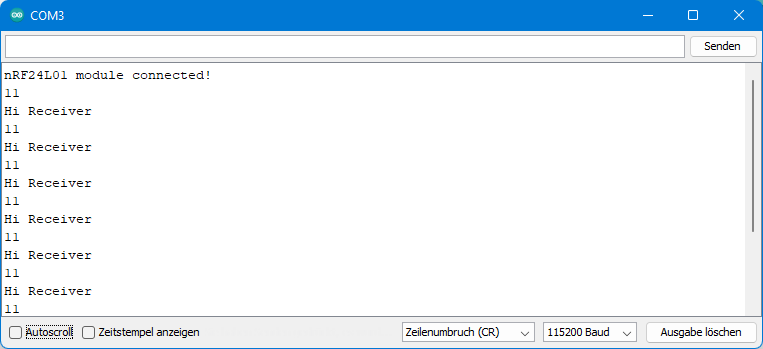
And here is the output. As expected, 11 bytes were received:
The nRF24L01 as MultiCeiver™.
As a receiver, the nRF24L01 can “listen” to six transmitters simultaneously. However, the restriction applies that only one message can be received at any given time. This is where the repetitions come in.
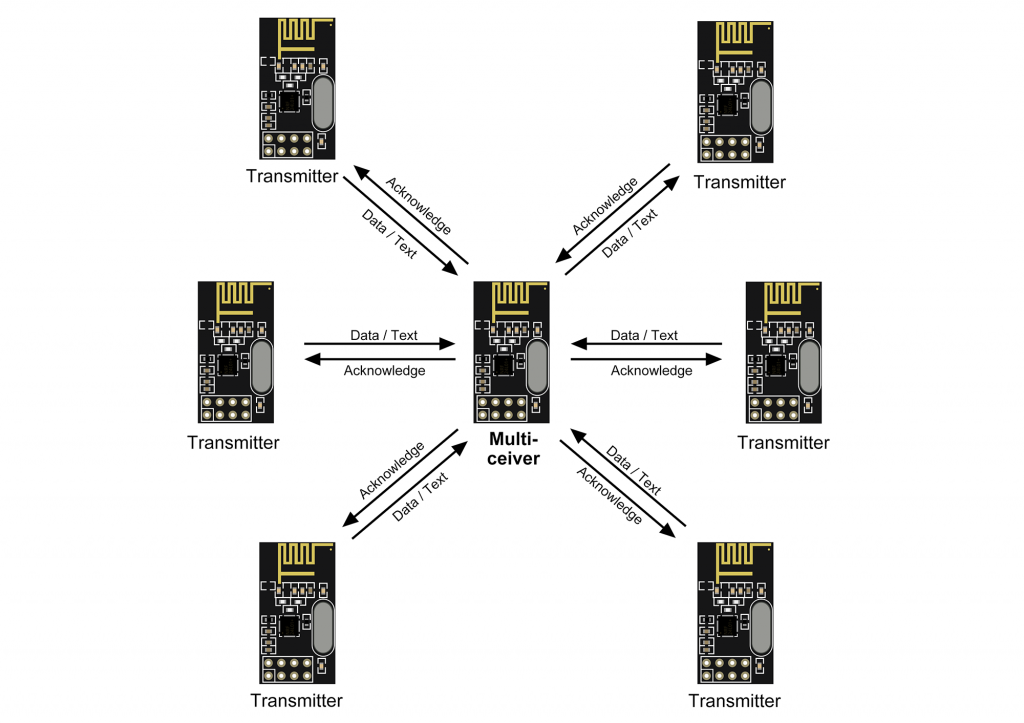
We’ll start with the receiver side this time. The nRF24L01 uses its six pipes here. Each of the pipes gets an individual reading pipe address, which must match the writing pipe address of the corresponding transmitter.
Now it gets a bit confusing again: Only the address of pipe 0 consists of individual 5 bytes. The addresses of the lines 1 to 5 differ only by byte 0. These addresses “share” bytes 1 to 4 of the address of pipe 1. Thus, the scheme is:
- Address 0 is “abcde”.
- Address 1 to 5 is: “fghij”, “kghij”, “lghij”, “mghij”, “nghij”.
- Here, a to n stand for any printable character.
And this system also explains why you could choose only the reading pipe 0 or 1 for the minimum_receiver_sketch (remember?): If the address of pipe 1 is not defined, the bytes 1 – 4 of the addresses of pipes 2 – 5 are not defined either.
Here is the receiver sketch:
#include <SPI.h>
#include "RF24.h"
RF24 radio(7, 8); // (CE, CSN)
const byte address[][6] = {"0Base", "1RF24", "2RF24", "3RF24", "4RF24", "5RF24"};
void setup() {
Serial.begin(115200);
radio.begin();
radio.setPALevel(RF24_PA_LOW); // sufficient for tests side by side
for(int i=0; i<6; i++){
radio.openReadingPipe(i, address[i]);
}
radio.startListening(); // set as receiver
}
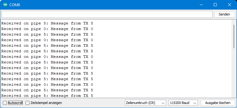
void loop() {
byte pipe;
if(radio.available(&pipe)){
char receivedText[33] = {0};
radio.read(&receivedText, sizeof(receivedText));
Serial.print("Received on pipe ");
Serial.print(pipe);
Serial.print(": ");
Serial.println(receivedText);
}
}
A new feature of this sketch is that the variable pipe is passed to the function available() (as a reference). This allows us to check which pipe received the message. All other functions have already been discussed.
And now we get to the transmitter sketch for module 0. To adapt it for the other five transmitter modules, you only have to change the transmitter ID tx_id in line 8.
#include <SPI.h>
#include <RF24.h>

RF24 radio(7, 8); // (CE, CSN)

const byte address[][6] = {"0Base", "1RF24", "2RF24", "3RF24", "4RF24", "5RF24"};

byte tx_id = 0; // max. 6 TX: 0...5

void setup() {
  Serial.begin(115200);
  radio.begin();
  radio.setPALevel(RF24_PA_LOW); // sufficient for tests side by side

  radio.openWritingPipe(address[tx_id]); // set the address
  radio.stopListening();
  radio.setRetries(((tx_id * 3) % 12) + 3, 15);
}
void loop() {
  char text[32] = {0};
  strcpy(text, "Message from TX ");
  char buf[2] ={0};
  itoa(tx_id, buf, 10);
  strcat(text, buf);
  Serial.println(text);

  if(radio.write(&text, sizeof(text))){
    Serial.println("Message successfully sent");
  }
  delay(3000);
}
A few more notes. The peculiar construction for the retry delay in line 17 is to ensure that the retries are sent by the modules at different intervals. This avoids collisions (more precisely: repeated collisions).
Most of the code in loop() is used to compose the message:
strcpy(text, "Message from TX ")copies “Message from TX ” totext.itoa(tx_id, buf, 10)copies the integer valuetx_idas a string into the character arraybufusing the decimal system.strcat(text, buf)appendsbufto the end oftext.
If you want to send floats, you could use the function dtostrf():
dtostrf(float_value, min_width, num_digits_after_decimal, target). Wheremin_widthis the minimum width (>=4),num_digits_after_decimalis the number of digits after the decimal point andtargetis the character array which stores your value.
Note on the MultiCeiver example library sketch
If you look at the example sketch MulticeiverDemo.ino of the RF24 library, you might stumble over the address definition there:
uint64_t address[6] = { 0x7878787878LL,
                        0xB3B4B5B6F1LL,
                        0xB3B4B5B6CDLL,
                        0xB3B4B5B6A3LL,
                        0xB3B4B5B60FLL,
                        0xB3B4B5B605LL };
The addresses are defined in this sketch as an array of 6 integers with a size of 8 bytes each. This takes a bit more space than the six arrays of 6 bytes each. But that is not yet the point. Rather, the question could arise why the byte on the right is different for addresses 1 to 5 and not the one on the left. The answer is that the byte 0 of an integer is on the far right, whereas the 0th element of an array is on the left.
Changing the role of the nRF24L01
You can change the role of the nRF24L01 as transmitter or receiver during the running program. The following sketch turns the nRF24L01 into a transmitter that sends a message every two seconds. If the message was sent successfully, the sketch outputs a success message and the transmitter becomes the receiver. If the nRF24L01 has received a message as a receiver, this message is output and it becomes the transmitter again.
This means that the module running with this sketch controls the timing. That’s why I named the sketch “leading_transceiver.ino”:
#include <SPI.h>
#include <RF24.h>

RF24 radio(7, 8); // (CE, CSN)

const byte address[6] = "_no_1"; // address / identifier

void setup() {
  Serial.begin(115200);
  radio.begin();
  radio.setPALevel(RF24_PA_LOW); // sufficient for tests side by side

  radio.openWritingPipe(address); // set the address
  radio.openReadingPipe(1,address);
}
void loop() {
  unsigned long int sendingPeriod = 2000;
  static unsigned long int lastSend = 0;
  const char sendText[] = "Hi Follower";

  if((millis()-lastSend)>sendingPeriod){
    radio.stopListening(); // set as transmitter
    lastSend = millis();
    if(radio.write(&sendText, sizeof(sendText))){
      Serial.println("Message successfully sent");
      radio.startListening();
    }
  }
  if(radio.available()){
    char receivedText[33] = {0};
    radio.read(&receivedText, sizeof(receivedText));
    Serial.print("Message received: ");
    Serial.println(receivedText);
    radio.stopListening();
  }
}
The module on the other side starts as a receiver. If it receives a message, it is output and the module becomes a transmitter. As a transmitter, it sends back a message and becomes a receiver again.
If things go badly, both modules might wait for each other for all eternity without anything happening. For this purpose, I have inserted lines 18 – 20. Once per second, the module is reminded to take over the receiver role.
#include <SPI.h>
#include "RF24.h"

RF24 radio(7, 8); // (CE, CSN)

const byte address[6] = "_no_1"; // address / identifier
void setup() {
  Serial.begin(115200);
  radio.begin();
  radio.setPALevel(RF24_PA_LOW); // sufficient for tests side by side

  radio.openReadingPipe(0,address); // set the address
  radio.openWritingPipe(address);
  radio.startListening(); // set as receiver
}

void loop() {
  if((millis()%1000) == 0){
    radio.startListening();  // gentle reminder to listen
  }
  if(radio.available()){
    char receivedText[33] = {0};
    radio.read(&receivedText, sizeof(receivedText));
    Serial.print("Message received: ");
    Serial.println(receivedText);

    radio.stopListening();
    const char sendText[] = "Hi Leader";
    if(radio.write(&sendText, sizeof(sendText))){
      Serial.println("Message successfully sent");
      radio.startListening();
    }
  }
}
Extended Acknowledgements
In the previous example, one module was mainly transmitter and the other mainly receiver. The receiver should only send back a message if it had previously received a message from the transmitter. For this constellation there is a simpler solution, namely you can send data with the acknowledgement. Piggyback, so to speak. The advantage is that you do not have to change the role of the modules.
The function that activates this feature is enableAckPayload(). It must be called on the transmitter side as well as on the receiver side. You can check whether there is a response from the receiver with available(). If this is the case, you can read the message as usual with read().
#include <SPI.h>
#include <RF24.h>

RF24 radio(7, 8); // (CE, CSN)

const byte address[6] = "_no_1"; // address / identifier

void setup() {
  Serial.begin(115200);
  radio.begin();

  radio.openWritingPipe(address); // set the address for writing
  radio.openReadingPipe(1, address);  // set the address for reading
  radio.stopListening(); // set as transmitter
  radio.setPALevel(RF24_PA_LOW); // sufficient for tests side by side

  radio.enableDynamicPayloads();
  radio.enableAckPayload();
}
void loop() {
  unsigned long int sendingPeriod = 2000;
  static unsigned long int lastSend = 0;
  const char text[] = "Hi Receiver";

  if((millis()-lastSend)>sendingPeriod){
    lastSend = millis();
    if(radio.write(&text, sizeof(text))){
      Serial.println("Message successfully sent");
    }
  }
  if(radio.available()){
    Serial.print("Received: ");
    byte len= radio.getDynamicPayloadSize();
    char ackPayload[len] = {0};
    radio.read(&ackPayload, len);
    Serial.println(ackPayload);
  }
}
And this is how the receiver side looks like:
#include <SPI.h>
#include "RF24.h"

RF24 radio(7, 8); // (CE, CSN)

const byte address[6] = "_no_1"; // address / identifier

void setup() {
  Serial.begin(115200);
  radio.begin();

  radio.openReadingPipe(0,address); // set the address for writing
  radio.openWritingPipe(address); // set the address for reading
  radio.startListening(); // set as receiver
  radio.setPALevel(RF24_PA_LOW); // sufficient for tests side by side

  radio.enableDynamicPayloads();
  radio.enableAckPayload();
  char ackPayload[] = "First Answer";
  radio.writeAckPayload(0, &ackPayload, sizeof(ackPayload));
}

void loop() {
  static float counter = 0.0;
  if(radio.available()){
    byte len = radio.getDynamicPayloadSize();
    char text[len+1] = {0};
    radio.read(&text, sizeof(text));
    Serial.println(text);

    //Acknowledgement Payload:
    char ackPayload[16];
    strcpy(ackPayload, "counter ");
    char number[12] = {0};
    dtostrf(counter, 4, 2, number);
    Serial.println(number);
    strcat(ackPayload, number);
    Serial.println(ackPayload);
    counter += 1.0;
    radio.writeAckPayload(0, &ackPayload, sizeof(ackPayload));
  }
}
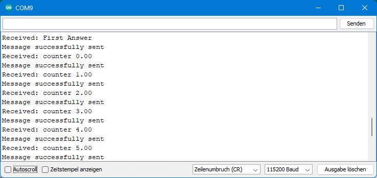
You write the answer to the transmitter with writeAckPayload(pipe, text, size) into the FIFO. It will be sent immediately after receiving the message. I.e. you have to formulate the answer before you get the message. For example, if the response includes the measured value of a sensor, then it is not quite up to date. Either you live with it, or:
- You write an update to the FIFO regularly.
- The transmitter sends its message twice in quick succession, and you discard the first response each time.
- You do go back to the method where you switch roles.
So that it does not become too boring because always the same answers of the receiver are received, the receiver sends back a counter reading in this example. This is also where dtostrf() comes in.
This is the output of the transmitter side:
Using interrupts of the nRF24L01
The nRF24L01 can signal three events by an interrupt:
- Data has been sent.
- The data transmission has gone wrong.
- Data is available for retrieval from the FIFO.
To switch the interrupts on or off, use the function maskIRQ(data_sent, data_fail, data_ready). A “0” for data_send, data_fail or data_ready activates the interrupt, a “1” masks it.
The IRQ pin is active-low. That means you should set the interrupt on the Arduino to FALLING.
If you have activated more than one of the three interrupt triggers, you can use whatHappened(data_sent, data_fail, data_ready) to find out which one caused the last interrupt. The “guilty” parameter has the value 1.
The following sketch uses the Data Ready interrupt to indicate that data has been received. Accordingly, the query if radio.available() can be omitted. This particular example does not provide any real benefit, but is for illustrative purposes only. A more sensible use of the Data Ready Interrupt would be, for example, to wake the microcontroller from sleep mode.
#include <SPI.h>
#include "RF24.h"
#define IRQ_PIN 2
volatile bool event = false;
RF24 radio(7, 8); // (CE, CSN)
const byte address[6] = "_no_1"; // address / identifier
void setup() {
Serial.begin(115200);
radio.begin();
radio.openReadingPipe(0,address); // set the address
radio.startListening(); // set as receiver
pinMode(IRQ_PIN, INPUT);
attachInterrupt(digitalPinToInterrupt(IRQ_PIN), interruptHandler, FALLING);
// let IRQ pin only trigger on "data ready" event in RX mode
radio.maskIRQ(1, 1, 0); // args = "data_sent", "data_fail", "data_ready"
}
void loop() {
if(event){
//if(radio.available()){
char text[33] = {0};
radio.read(&text, sizeof(text)-1);
Serial.println(text);
//}
event = false;
}
}
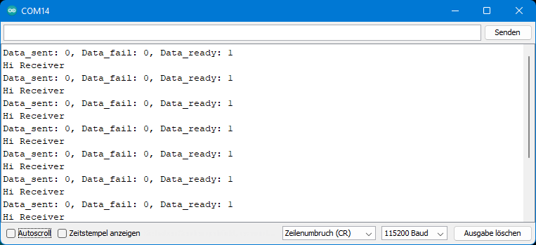
void interruptHandler(){
event = true;
bool tx_ds, tx_df, rx_dr; // declare variables for IRQ masks
radio.whatHappened(tx_ds, tx_df, rx_dr); // get values for IRQ masks
Serial.print("Data_sent: ");
Serial.print(tx_ds); // print "data sent" mask state
Serial.print(", Data_fail: ");
Serial.print(tx_df); // print "data fail" mask state
Serial.print(", Data_ready: ");
Serial.println(rx_dr); // print "data ready" mask state
}
And this is the output:
More functions
I have not covered all the functions in my example sketches. I would like to point out a few of the missing features, as I find them particularly useful. However, I only deal with them superficially.
writeFast()is similar towrite().write()writes the message into the FIFO and waits until it is sent.writeFast(), on the other hand, does not wait, but further messages can be written into the FIFO buffer until all three FIFOs are full. Only then does the program block until FIFO capacity is free again. For large amounts of data, this gives some speed advantage.powerDown()puts your nRF24L01 into deep sleep, in which it consumes only 0.9 µA of current.powerUp()is the counterpart to this.flush_rx()andflush_tx()clear the FIFO of the receiver and the transmitter, respectively.printDetails(),printPrettyDetails()andsprintfPrettyDetails()are useful for debugging. The functions show the status and settings of the nRF24L01.
For more information on these and other features, see the class documentation or the example sketches of the library.
Indoor range test
I did a range test at my house. Without barriers, you might be able to reach the maximum ranges, but indoors, of course, you can’t because of the walls and furniture. External radio signals such as WLAN can also interfere.
I chose the maximum PA level for the test and the lowest data transfer rate. Two power supplies were used on both the transmitter and receiver side. The Arduino Nano was powered by a 9 volt block battery via VIN. I operated the nRF24L01 module with a lithium-ion battery. The latter is not generally recommended, since the battery supplies up to 4.2 volts when freshly charged. My batteries were already somewhat discharged. At ~3.8 volts, they were a little above the specification limit of 3.6 volts. For a short time, this is justifiable. I added a huge electrolytic capacitor with 470 µF to the power supply of the nRF24L01.
I only show the receiver sketch:
#include <SPI.h>
#include "RF24.h"
const int ledPin = 6;

RF24 radio(7, 8); // (CE, CSN)

const byte address[6] = "_no_1"; // address / identifier

void setup() {
  pinMode(ledPin, OUTPUT);
  radio.begin();
  radio.openReadingPipe(0,address); // set the address
  radio.startListening(); // set as receiver
  radio.setPALevel(RF24_PA_MAX);
  radio.setDataRate(RF24_250KBPS);
}

void loop() {
  if(radio.available()){
    char text[33] = {0};
    radio.read(&text, sizeof(text)-1);
    String textString = String(text);
    if(textString == "Hi Receiver"){
      digitalWrite(ledPin, HIGH);
      delay(300);
      digitalWrite(ledPin, LOW);
    }
  }
}
I positioned the transmitter in a corner of the house. It sent the message “Hi Receiver” every two seconds. When the transmission was correct, the LED on the receiver side flashed briefly. Then I walked through the house with the receiver and checked where the LED was blinking and where it wasn’t (which my family noted shaking their heads).
Result for the standard module
I was able to receive the messages in the neighboring room without any problems. One room over, I could only receive the news near the door. The indoor range, of course, depends largely on the building fabric of the house. A better comparison could be the following: The range was roughly comparable to the range of the 2.4 GHz WLAN of my router (Fritz!Box 7590). This also does not cover the whole house and must be supported by a repeater. So if you want to use the nRF24L01 in your apartment or house, do not assume that this will necessarily work with the standard modules.
Result for the “nRF24L01 + PA + LNA” module
As mentioned at the beginning, I first had to shield the “nRF24L01 + PA + LNA” modules with aluminum foil to make them work at all (yes, aluminum hats are of some use here 😉 ). But then the range was much better than the standard modules. Problems only occurred when sending messages from the basement to the attic.