
About the post
Actually, I had completed my series on light and proximity sensors with my last summary post. For me, however, the question arose whether you can also build an IR proximity sensor yourself (IR = infrared). That is what this article is about.
Concepts
At first, I asked myself the question even more general: Can you build proximity sensors or motion sensors yourself with simple means? First, you need a physical size with which an approximation can be detected. I wanted a solution where the signal and sensor are controlled on only one side. So, not something like light barriers or magnet/hall sensor combinations.
When looking at the various physical methods like radar, light (time of flight), ultrasound, etc., I chose infrared light as the simplest solution. The sensor should therefore emit infrared light and detect the reflected signal. Basically, there are two possibilities, namely pulsed and non-pulsed infrared radiation. I will start with the latter.
Build IR proximity sensor yourself: non-pulsed option
LED selection
An LED is best used as an infrared radiation source. These are mainly available with wavelengths of 850 or 940 nm. The receiver is an infrared photodiode. You get both, often in a double pack, for little money, for example at Amazon. If you follow the link, you will find both three-pin and two-pin receivers. In this section we talk about the two-pin ones, in the next section (pulsed IR) about the three-pin ones.
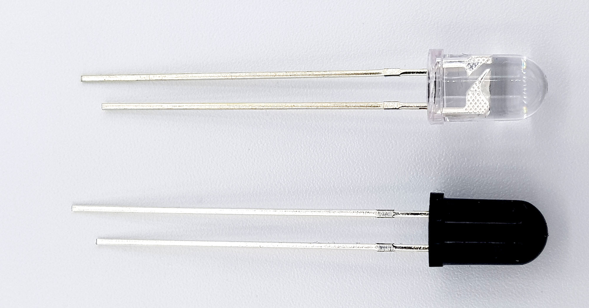
When selecting the IR LED, you should consider its power and not choose too low. The LEDs used for this post can tolerate up to 100 milliamperes at 1.2 to 1.5 volts.
Wiring
IR LED
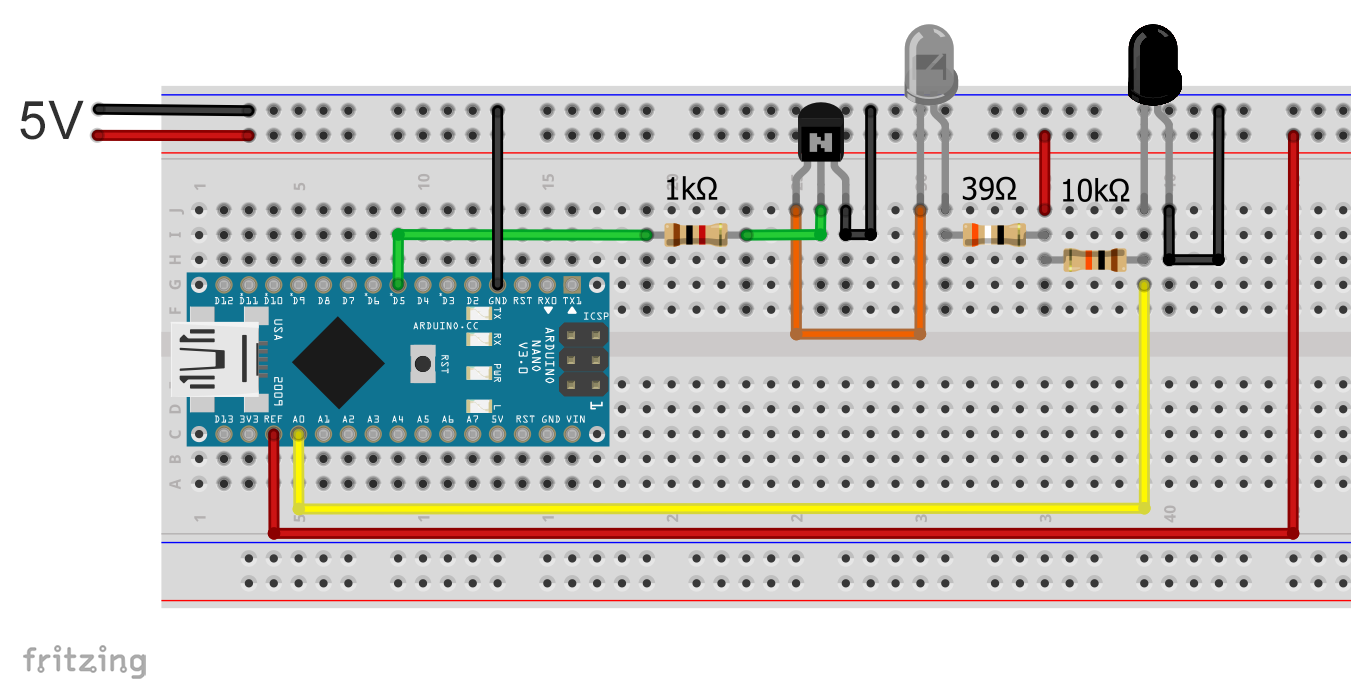
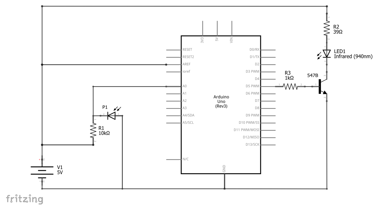
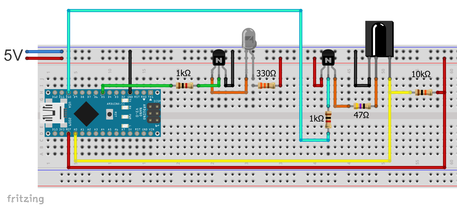
From the data above, you can already see that the IR LEDs play in a different league in terms of power consumption than conventional LEDs. Under no circumstances should you connect it directly to an I/O pin of your Arduino or other microcontrollers, as you usually might do. I decided to use an external 5V power supply. An Arduino I/O pin switches the IR LED via an NPN transistor (547B). This one can handle 100 milliamperes, but it must not be more.
1.2 to 1.5 volts drop across the IR LED and about 0.5 V across the transistor (see data sheet). With VCC = 5 volts, this leaves 3.0 to 3.3 volts for the series resistor. At 100 mA current, you would have to use a resistor of 35 to 38 ohms accordingly. I used a 39 Ohm resistor and measured 84 milliamps.
The photodiode side
The photodiode is connected in the locking direction (!). It hurts somehow, doesn’t it? But it’s like that because infrared radiation is making it permeable proportional to the radiation intensity. As the current increases, voltage drop across the resistor also increases. And with that we have our measure for proximity measurement.
And what is the connection to ARef?
For voltage measurements by analogRead() and use of an external voltage source for the sensor, the external voltage source should be taken as the reference value. It’s not so relevant here, but it’s more accurate.
On the breadboard
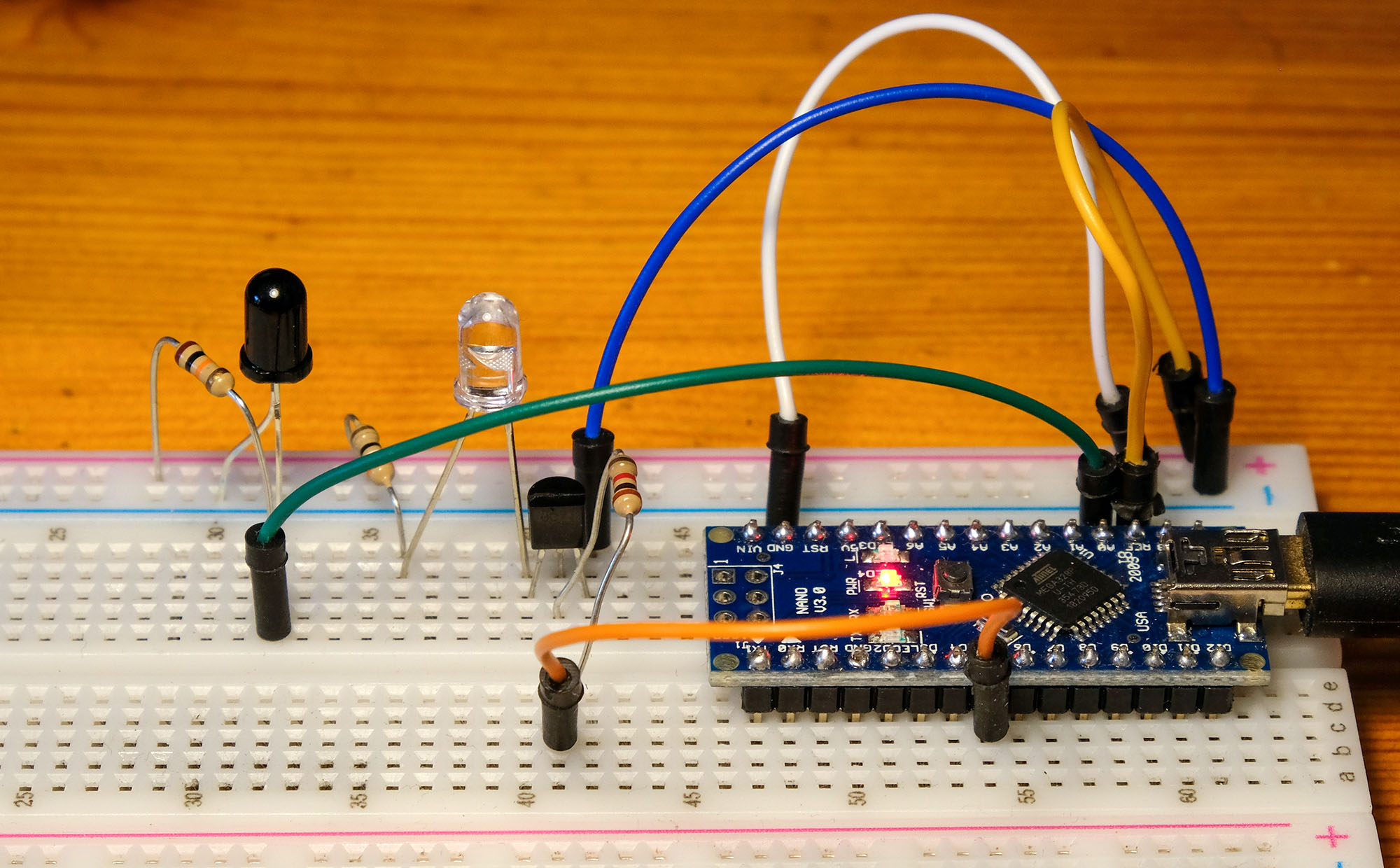
Some may wonder whether the IR LED does not radiate too much directly onto the photocell when set up. However, the influence is limited, as the IR LED mainly radiates upwards.
The external power supply
A small tip: as an external power supply for breadboard tests, I recommend the following module that you can plug directly into the breadboard:

There’s something like that – where do you think? – yes exactly, at Amazon, for example.
The sketch (non-pulsed)
First, the Arduino reads the signal when IR LED is turned off. In this way, we measure the influence of IR ambient radiation (“baseSignal”), caused e.g. by lamp- or daylight. Individual measurements can vary quite widely. That’s why the Arduino reads fifty values and mediates them. I could stabilize the values considerably by inserting a pause of 500 microseconds between the individual measurements. Then the Arduino switches the IR LED on, measures fifty values again and mediates it (rawSignal). The difference is the dimensionless proximity value.
At fifty readings, an “unsigned int” would suffice for baseSignal and rawSignal. I also played with more readings in between. Therefore, these variables are defined as “unsigned long”.
An Arduino takes about 100 microseconds for a single analogRead(). Fifty measurements take 50 x (500 + 100) microseconds, i.e. about 3 milliseconds. Only for this time the IR LED is switched on. Since only one measuring cycle takes place per second, the power consumption is kept within limits, despite the power-eating IR LED.
const int irLEDPin =  5;
const int irReceiverPin = A0;
unsigned long baseSignal, rawSignal;
unsigned int proximity;

void setup()   {
  Serial.begin(9600);
  analogReference(EXTERNAL);
  pinMode(irLEDPin, OUTPUT);
}

void loop(){
  baseSignal = 0;
  rawSignal = 0;
  delay(1000);

  for(int i=0; i<50; i++){
    baseSignal += analogRead(irReceiverPin);
    delayMicroseconds(500);
  }
  baseSignal /= 50;
  Serial.print("Ambient IR Light: "); Serial.print(baseSignal);

  digitalWrite(irLEDPin, HIGH);
  for(int i=0; i<50; i++){
    rawSignal += analogRead(irReceiverPin);
    delayMicroseconds(500);
  }
  rawSignal /= 50;
  Serial.print("   Raw Signal: "); Serial.print(rawSignal);
  proximity = baseSignal - rawSignal;
  Serial.print("   Proximity: "); Serial.println(proximity);
  digitalWrite(irLEDPin,LOW);
}
The result
With the parameters, I have chosen, i.e. especially the IR current, the self-built sensor has a range of about fifty to sixty centimeters. The range depends, of course, on the size of the object, its surface structure and the material. Some materials reflect IR radiation very well, others absorb a large part. A white A4 paper was detected up to more than seventy centimeters.
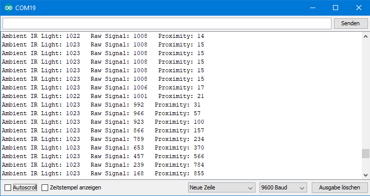
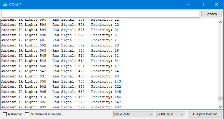
The screenshots below show the output on the serial monitor when I approached the photodiode with my hand.
The first screenshot shows the result in low ambient light, namely in the evening and in low ceiling light. The measured value for non-switched IR LED (Ambient IR Light) is 1022 to 1023, i.e. the photodiode is almost impermeable. When IR LED (Raw Signal) is switched on and no object in range, the measured value is approx. 1008. So, a small current flows through the photodiode. This is due to the cross-radiation of the IR LED to the photodiode and by diffuse reflection on walls and objects. As the approach progresses, the resistance of the photodiode decreases. The difference between the Raw Signal and the Ambient IR Light becomes correspondingly large.
The second screenshot shows the result influenced by my 40 watt halogen desk lamp (light from obliquely above so that it does not reflect the IR signal) at about fifty centimeters distance. The ambient IR light value is correspondingly low (i.e. a lot of ambient light), but nevertheless you get a clear signal from the approaching object. It is interesting that the ambient IR Light value first decreases slightly when approaching and then rises. Explanation: first my hand reflects the light of the desk lamp and therefore provides more light, then it increasingly obscures it.
Build IR proximity sensor yourself: pulsed option
Pulsed IR signals
I will write about infrared transmitters (remote controls) in one of my next posts. That is why I do not want to go into too much detail at this point. Only so much: pulsed infrared light is used in transmission technology. The pulse rate is usually 38 kilohertz. On the transmitting side you can use the same IR LEDs, but with a pulsed signal. The trick is on the receiver side. which “understands” only the pulsed signals. This has the advantage that the transmission is not affected by the ambient light. The receiving photodiodes are the above mentioned three-pin ones:

You can find these receivers under the designation VS1838B or TSOPxx38 with xx = z.B. 18, 22, 24, 48. If the designations do not end with 38, e.B. TSOP2256, then the pulse rate is not 38 kHz, but in this example 56 kHz.
Here is a functional diagram of an IR receiver:
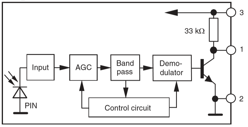
The receiver amplifies and demodulates the incoming signal, i.e. it turns a pulse signal into a continuous signal. If a signal is detected, the transistor between 1 and 2 opens or a Schmitt trigger is used. This leads to a voltage drop at pin 1.
Wiring
IR LED
First, a pulsed signal must be sent. This can be easily done on a PWM-capable (pulse width modulation) Arduino Pin. However, an IR receiver for pulsed signals is much more sensitive than the previously used photodiode. If you use the same IR LED current as above, then there is a permanent signal due to the lateral radiation and by reflection of walls and objects further away. Finally, it worked with a 330 Ohm resistor for the IR LED. Just try it out. And maybe you want to use a potentiometer instead of the fixed size resistor.
The circuit worked reliably only if I a) used a transistor on the receiver side at all, b) placed the receiver behind the transistor (which you really don’t do) and c) only with the receiver model with metal case. When using alternative IR receivers, I found that they again needed different settings. The whole thing is quite a fiddly job and only limited recommended for rebuilding!
Note: The assignment of the pins of the receiver module may vary. Look at your module’s data sheet!

The receiver side
An IR receiver for pulsed signals draws about 0.6 milliamperes of current. That’s not much. But things add up and especially with battery-powered projects you probably want to keep the power consumption low. That’s why I only switch on the receiver via a transistor when it is actually needed.
On the breadboard
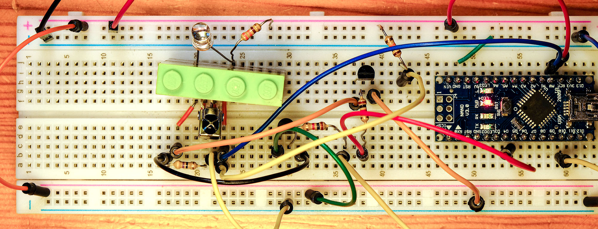
Even with the reduced IR LED current, I still had to shield the receiver diode against the IR LED. I solved this here provisionally-pragmatically with a few Lego bricks, which I borrowed from my son. I also buckled the receiver module’s legs by 90 degrees.
The sketch
The sketch is even simpler than the non-pulse method, as you don’t need the measurement of ambient light. The 38 kilohertz signal is generated via the tone() function and switched off by noTone(). Again I inserted a pause between each measurement, but this time 50 microseconds were sufficient. However, I had to send a 10 millisecond signal (line 20) as a starting sequence in advance to get reasonable values. This is related to the AGC (automatic gain control) unit in the receiver (see schema above). It ensures an automatic amplification of the signal, but it takes a bit of time to adjust.
const int irLEDPin =  5;
const int irReceiverDataPin = A0;
const int irReceiverEnablePin = 10;
unsigned long proximity;


void setup()   {
  Serial.begin(9600);
  analogReference(EXTERNAL);
  pinMode(irReceiverEnablePin, OUTPUT);
  pinMode(irLEDPin, OUTPUT);
}

void loop(){
  proximity = 0;
  delay(1000);

  tone(irLEDPin, 38000);
  digitalWrite(irReceiverEnablePin, HIGH);
  delay(10);
  for(int i=0; i<50; i++){
    proximity += analogRead(irReceiverDataPin);
    delayMicroseconds(50);
  }
  proximity /= 50;
  Serial.print("Proximity: "); Serial.println(proximity);
  noTone(irLEDPin);
  digitalWrite(irReceiverEnablePin, LOW);
}
The result
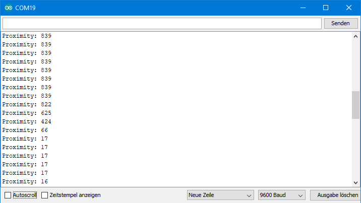
I tried to approach the sensor at a similar speed as above. You see a high value when no object is in range because the transistor in the receiver is locked. When an object comes within range, the value goes to a minimum rapidly and remains constant. Due to the internal design, the receiver module reacts virtually digitally. In the short transition range with medium values, some signals arrive and others do not.
The range of this variant is similar to the non-pulse method for the selected parameters. However, after about twenty to thirty percent of detection range, the minimum reading has been reached. This set-up is therefore more of a motion detector than a proximity sensor.
Since the receiver only provides a HIGH / LOW signal, the function can also be analogRead() replaced by the faster digitalRead()function. Then, however, one should no longer divide by the number of measurements to capture the transition area. You can try that out.
Acknowledgement
The picture with hammer and nails, into which I pixelated the IR LEDs, receiver and ruler for my post image, comes from analogicus on Pixabay. The ruler comes from mbnachhilfe_de, also Pixabay.