About this post
I had already reported about the SI1145 in my last post about UV sensors. However, the SI1145 can do much more, namely ambient (ALS/VIS) and infrared light (ALS/IR) measurements, and you can also use it as a proximity sensor (PS). Unfortunately, I couldn’t find a library that would make all these options accessible with the associated settings. That’s why I wrote a library myself (SI1145_WE), which you can find here on Github. Or you can install it through library management in the Arduino IDE.
I would like to introduce the library in this post, but I will discuss the properties of the SI1145 (module) beforehand. The post has become very long – but that reflects that the SI1145 is a complex device. If you’re too bored, go to the library right away. But with more background knowledge, it is easier to understand.
Features of the SI1145
Key technical data
- Distance measurement from 1 cm to > 50 cm
- Light measurement from 1 to 128000 Lux
- Power consumption in the microampere range
- <500 Nanoamperes on standby
- Supply voltage:1.71 – 3.6 volts
- for modules mostly 3 – 5 volts
- Communication via I2C
- Address: 0x60 specified, adjustable via register
Ambient light measurements (ALS VIS/IR)
Measuring principle / procedure
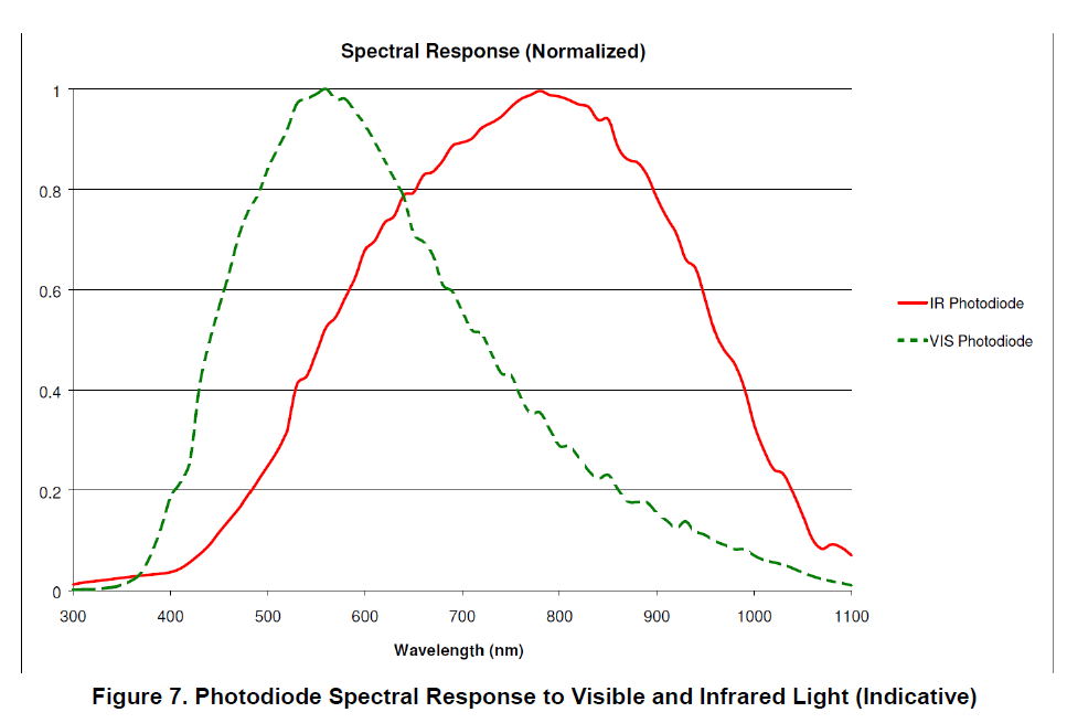
The SI1145 has one photodiode for the visible and two photodiodes for the infrared spectrum. The two IR photodiodes differ in their size and thus in their sensitivity. They have two tasks. On the one hand, they are used for correction in ambient light measurement because this interferes with the proportion of infrared light. On the other hand, they serve as detectors for distance measurements. You can choose which IR photodiode you assign to which function. For example, one will work in direct sunlight with the small diode, since the large diode will overflow under these conditions (or the downstream A/D converter).
The VIS and IR measurements take place one after the other. The SI1145 is very fast. Typically, a VIS/IR measurement in a double pack takes only 285 microseconds.
The SI1145 stores the results of the measurements in the 16-bit data registers (2 x 8 bits each to be exact) for the visible and infrared range. These raw data have to be processed further, for example to calculate the light intensity in lux.
Settings
For the VIS and IR measurements, the measurement time (gain, integration time) can be set. You can choose a factor between 1 and 128. The measuring time is then 25.6 µs x 2^GAIN with GAIN = 0 to 7. For particularly strong light, the SI1145 offers a “High Signal Range Mode” corresponding to a gain factor of 1/14.5.
In addition, you can (theoretically) set the minimum regeneration time for the A/D converter before performing the next measurement. However, I adhered to the data sheet recommendation in my library and implemented a gain-dependent algorithm.
The A/D converter has an unusual resolution of 17 bits. By default, the top 16 bits are transferred to the data registers. You can also use the lower 16 bits. This doubles the resolution, but halves the upper limit accordingly.
The provision of the measured values in the data register can be indicated by an interrupt.
Lux calculations
Getting reliable lux values out of light sensors is generally a science in itself because:
- The photodiodes for the visible area are influenced by the infrared light.
- Within the visible range, the photodiodes have different sensitivities depending on the wavelength and thus respond differently to different light sources (sunlight, incandescent lamp, LED (cold/white), halogen, etc.).
The problem related with infrared light can be solved by additional sensors which subtract the proportion of infrared light.
The problem of sensor characteristics, on the other hand, can only be solved by calibrating to different light sources. Even commercially available light sensors have this problem. Often they are calibrated to light bulbs, which is hardly to be found.
Here is an example of two light sensors, which differ 5% for incandescent light according to my < measurements. On the other hand, the results with overcast sky (i.e. cold light) differ by about 40% in relation to the lower value:

Considering this, one should perhaps reduce one’s expectations on the exactness of self-built light sensors a little. But at least you should be aware that exact measurements involve a certain amount of effort.
The whole thing becomes even more complex when you use the SI1145 under covers that absorb a certain amount of visible and infrared light.
Calculation formula for the SI1145
In the Application Notes AN523 (Overlay considerations for the Si114X sensor) I found the following formula for lux calculation on page 3:

The two coefficients in case no coverage is used can be found on the next page of application notes AN523:
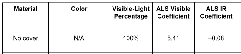
The ALS / ALSIR values in the above equation are the values read from the sensor at current light or in the dark (“dark reading”). The dark values must be determined once. However, the formula applies only to the following boundary conditions:
- IR and VIS gain = 0
- Normal signal range
- Use of the small IR photodiode.
If you deviate from this, you have to apply correction factors.
With this formula, I achieved results that were within the range of the results of my commercial light sensor. From my point of view, however, there would still have to be a weighting by the count-per-lux factors (see data sheet, p. 6-7). In my example sketch SI1145_lux_calculation I therefore offered an alternative in addition to the standard formula.
If you want to get more into this topic, you should read the AN576 and the AN498 in addition to the AN523. I have focused more on mastering the SI1145 than on the subsequent processing of the raw data. Therefore, and because the lux calculation can be adjusted very individually, I did not implement it in the library itself.
Distance measurements (PS)
Measuring principle / procedure
The SI1145 does not have an integrated IR LED. You have to connect them separately to the LED pin (with the minus pole to the sensor by the way). The “bigger brothers” SI1146 and SI1147 even offer the option to connect two or three IR LEDs and perform separate PS measurements. Unfortunately, they do not exist as a module.
The minimum pulse duration for the IR LED is 25.6 microseconds. Depending on the setting, the radiation reflected by objects is detected by the large or small IR photodiode. Within a measurement cycle, the SI1145 always performs the PS measurement first and then the VIS/IR measurements.
The results of the PS measurements can be found in the 16-bit PS data register.
Settings
For PS measurements, the SI1145 allows the following settings:
- LED pulse width (gain): Factor 1 to 32
- LED current: from 5.6 to 360 mA
- High Signal Range Mode (as with ALS measurements)
- Selecting the top or lower 16 bits of the A/D converter
- (Regeneration time: again I followed the data sheet recommendations –> automatic setting with my library)
- Interrupt when providing the measurement result
UV index measurements
Here I refer again to my last post. I would just like to stress once again that there is no real UV radiation measurement, but the data from the VIS/IR data are extrapolated. The UV index data is stored in the corresponding data register. The UV index determination completes a measurement cycle.
General settings
In addition to the already listed special settings, there are a few general settings:
- Continuous or single-shot (forced) mode
- Measurement rate: the SI1145 enters sleep mode after a measurement and wakes up periodically. The measurement rate determines after how many sleep periods a measurement is performed.
- Query for overflows of the A/D converter in case of too strong light or too high gain
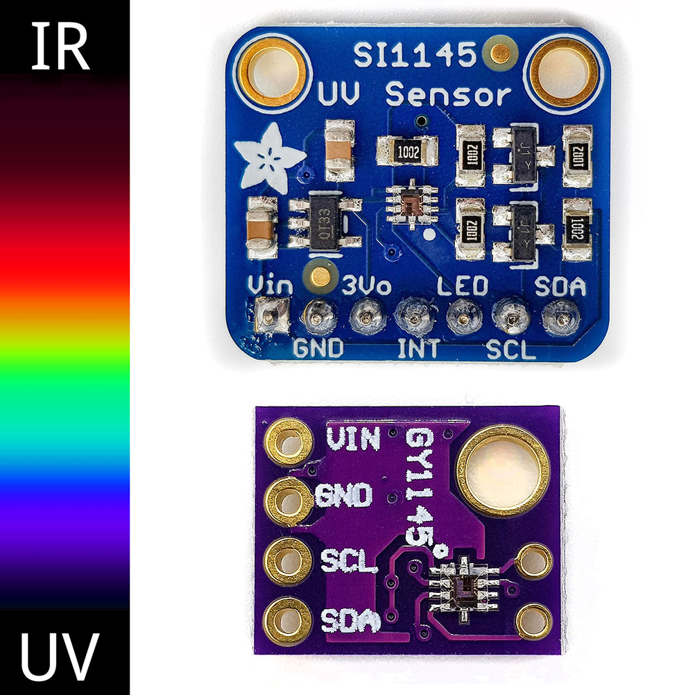
SI1145 modules
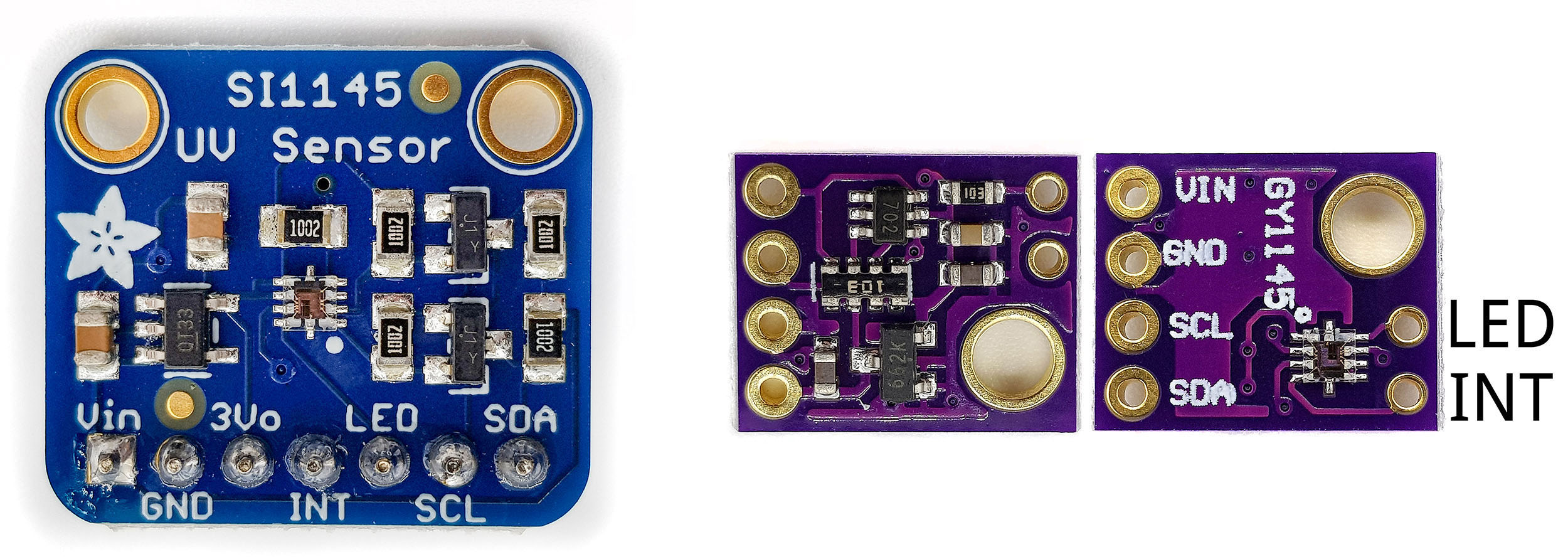
SI1145 modules are available in various versions, e.g. on Amazon or eBay. The price range is quite large with approx. 5 to 22 euros depending on the shop. Most modules have voltage control, so you can operate them between 3 and 5 volts. SDA, SCL and INT seem to have pull-up resistors, so you don’t have to worry about it. In any case, this applies to the modules I have tried.
The SI1145_WE Library
Now to the library. You can find it here on Github, along with the six example sketches that I’ll introduce in a moment. I have made most of the setting options accessible. Here is the list of public functions:

If you download the library, you will also get the function list in a better readable PDF format.
If you find bugs or miss features, get in touch. I promise short-term repairs!
The example sketches
Wiring the SI1145
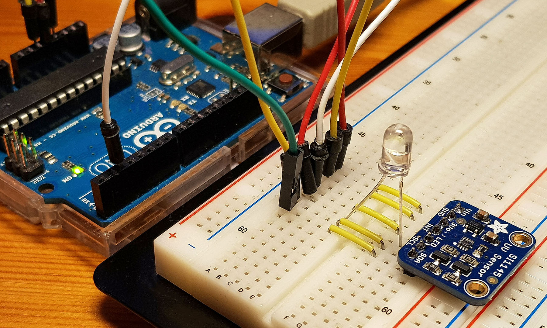
For the first five sketches that use only one SI1145, the following wiring can be applied. However, you only need the IR LED if you want to carry out PS measurements.

On the breadboard, it looks like this:
Example sketch 1 – Basics, continuous measurement
I have added many comments to the sketches. That is why I do not need to write much about it, I suppose. Basically, you have to determine which enableMeasurements() measurements you want to activate and whether they run continuously (AUTO) or as a single measurement (FORCE). You can use PAUSE to suspend continuous measurements.
In this first sketch, the SI1145 performs AS IR/VIS, PS and UV index measurements in continuous mode. Just play with the settings to become familiar with it.
#include <SI1145_WE.h>
#include <Wire.h>

SI1145_WE mySI1145 = SI1145_WE();
// You can also pass a Wire object like wire2:
// SI1145_WE mySI1145 = SI1145_WE(&wire2);

void setup() {
  Serial.begin(9600);
  Wire.begin();
  mySI1145.init();

  /* in case you want to change the I2C Address */
  //mySI1145.setI2CAddress(0x59);

  mySI1145.enableHighSignalVisRange(); // Gain divided by 14.5
  mySI1145.enableHighSignalIrRange(); // Gain divided by 14.5

  /* choices: PS_TYPE, ALS_TYPE, PSALS_TYPE, ALSUV_TYPE, PSALSUV_TYPE || FORCE, AUTO, PAUSE */
  mySI1145.enableMeasurements(PSALSUV_TYPE, AUTO);

  /* choose gain value: 0, 1, 2, 3, 4, 5, 6, 7 */
  //mySI1145.setAlsVisAdcGain(0);

  /* choose gain value: 0, 1, 2, 3, 4, 5 */
  //mySI1145.setPsAdcGain(0);

  /* if uncommented, the least 16 bit of the 17 bit ADC will be read */
  //mySI1145.enableHighResolutionVis();
  Serial.println("SI1145 - basics - continuous");
}

void loop() {
  byte failureCode = 0;
  unsigned int amb_als = 0;
  unsigned int amb_ir = 0;
  unsigned int proximity = 0;
  float uv = 0.0;

  amb_als = mySI1145.getAlsVisData();
  amb_ir = mySI1145.getAlsIrData();

  /* uncomment if you want to perform PS measurements */
  // proximity = mySI1145.getPsData();

  uv = mySI1145.getUvIndex();

  Serial.print("Ambient Light: ");
  Serial.println(amb_als);
  Serial.print("Infrared Light: ");
  Serial.println(amb_ir);
  Serial.print("UV-Index: ");
  Serial.println(uv);
  /* uncomment if you perform PS measurements */
  // Serial.print("Proximity: ");
  // Serial.println(proximity);
  failureCode = mySI1145.getFailureMode();  // reads the response register
  if((failureCode&128)){  // if bit 7 is set in response register, there is a failure
    handleFailure(failureCode);
  }
  Serial.println("---------");
  delay(1000);
}

void handleFailure(byte code){
  String msg = "";
  switch(code){
    case SI1145_RESP_INVALID_SETTING:
      msg = "Invalid Setting";
      break;
    case SI1145_RESP_PS1_ADC_OVERFLOW:
      msg = "PS ADC Overflow";
      break;
    case SI1145_RESP_ALS_VIS_ADC_OVERFLOW:
      msg = "ALS VIS ADC Overflow";
      break;
    case SI1145_RESP_ALS_IR_ADC_OVERFLOW:
      msg = "ALS IR Overflow";
      break;
    case SI1145_RESP_AUX_ADC_OVERFLOW:
      msg = "AUX ADC Overflow";
      break;
    default:
      msg = "Unknown Failure";
      break;
  }
  Serial.println(msg);
  mySI1145.clearFailure();
}
Example sketch 2 – continuous, interrupt-controlled
Also in this sketch, the SI1145 runs in automatic mode. However, you will see that the main loop does not contain any delay or that the delay is commented. The speed is controlled by the measurement rate. At the maximum (0xFFFF = 65535) applied here, a measurement takes place approximately every 2 seconds. You can test a different value. E.g. 0x8FFF to land at about one second. By the way, the default in my library is 0x00FF, which corresponds to a measuring frequency of about 8 milliseconds. In FORCED mode, the measurement rate is zero by definition.
The Arduino is “informed” about via the interrupt pin if a measured value is available. It is generally recommended doing this in continuous mode. Because if things run badly, then you read the data registers during an update and get the lower byte from the old measured value and the upper byte from the new measured value.
#include <SI1145_WE.h>
#include <Wire.h>
const int interruptPin = 2;

SI1145_WE mySI1145 = SI1145_WE();
// You can also pass a Wire object like wire2:
// SI1145_WE mySI1145 = SI1145_WE(&wire2);

void setup() {
  Serial.begin(9600);
  Wire.begin();
  pinMode(interruptPin, INPUT_PULLUP);
  mySI1145.init();
  //mySI1145.enableHighSignalVisRange();
  //mySI1145.enableHighSignalIrRange();

  /* SI1145 wakes up periodically - a measurement rate of x means that every x
   *  wake up a measurement is done; chose between 0 and 65535 - if you chose a low value
   *  you should uncomment the delay in the loop */
  mySI1145.setMeasurementRate(0xFFFF);

  /* choices: PS_TYPE, ALS_TYPE, PSALS_TYPE, ALSUV_TYPE, PSALSUV_TYPE || FORCE, AUTO, PAUSE */
  mySI1145.enableMeasurements(PSALSUV_TYPE, AUTO);

   /* choose gain value: 0, 1, 2, 3, 4, 5, 6, 7 */
  mySI1145.setAlsVisAdcGain(0);

   /* choose gain value: 0, 1, 2, 3, 4, 5 */
  mySI1145.setPsAdcGain(0);
  Serial.println("SI1145 - basics, interrupt controlled");
}

void loop() {
  byte failureCode = 0;
  unsigned int amb_als = 0;
  unsigned int amb_ir = 0;
  unsigned int proximity = 0;
  float uv = 0.0;

  mySI1145.clearAllInterrupts();

  /* wait until a measurement is completed -> interrupt goes LOW */
  while(digitalRead(interruptPin)){
  /* just wait for interruptpin to go LOW; if you have not set up the
     interrupt correctly you might wait forever! */
  }

  amb_als = mySI1145.getAlsVisData();
  amb_ir = mySI1145.getAlsIrData();
  proximity = mySI1145.getPsData();
  uv = mySI1145.getUvIndex();

  Serial.print("Ambient Light: ");
  Serial.println(amb_als);
  Serial.print("Infrared Light: ");
  Serial.println(amb_ir);
  Serial.print("UV-Index: ");
  Serial.println(uv);
  Serial.print("Proximity: ");
  Serial.println(proximity);

  failureCode = mySI1145.getFailureMode();  // reads the response register
  if((failureCode&128)){  // if bit 7 is set in response register, there is a failure
    handleFailure(failureCode);
  }
  Serial.println("---------");

  //Measuring frequency in this sketch is controlled by setMeasurementRate
  //delay(500);
}

void handleFailure(byte code){
  String msg = "";
  switch(code){
    case SI1145_RESP_INVALID_SETTING:
      msg = "Invalid Setting";
      break;
    case SI1145_RESP_PS1_ADC_OVERFLOW:
      msg = "PS ADC Overflow";
      break;
    case SI1145_RESP_ALS_VIS_ADC_OVERFLOW:
      msg = "ALS VIS ADC Overflow";
      break;
    case SI1145_RESP_ALS_IR_ADC_OVERFLOW:
      msg = "ALS IR Overflow";
      break;
    case SI1145_RESP_AUX_ADC_OVERFLOW:
      msg = "AUX ADC Overflow";
      break;
    default:
      msg = "Unknown Failure";
      break;
  }
  Serial.println(msg);
  mySI1145.clearFailure();
}
Example sketch 3 – forced ALS
You may have noticed that the VIS readings fluctuate quite a lot when the SI1145 is not in High Signal Range mode. This can be mitigated by averaging several readings.
In this example sketch, 50 readings are taken for one data point. This is happening here in Forced Mode. Each individual measurement must be started via startSingleMeasurement(). With getAlsVisData() and getAlsIrData() the data registers are read. However, these functions do not check whether the measurements have already been completed. You could insert a delay, but you would have to make sure you are on the safe side and would apply a more or less large buffer. The fastest way to perform the measurements succeeding is to control them by interrupts. The measured values are collected immediately after provision and the next measurement can begin.
#include <SI1145_WE.h>
#include <Wire.h>
const int interruptPin = 2;

SI1145_WE mySI1145 = SI1145_WE();
// You can also pass a Wire object like wire2:
// SI1145_WE mySI1145 = SI1145_WE(&wire2);

void setup() {
  Serial.begin(9600);
  Wire.begin();
  pinMode(interruptPin, INPUT_PULLUP);
  mySI1145.init();
  //mySI1145.enableHighSignalVisRange();
  //mySI1145.enableHighSignalIrRange();

  /* choices: PS_TYPE, ALS_TYPE, PSALS_TYPE, ALSUV_TYPE, PSALSUV_TYPE || FORCE, AUTO, PAUSE */
  mySI1145.enableMeasurements(ALS_TYPE, FORCE);

   /* choose gain value: 0, 1, 2, 3, 4, 5, 6, 7 */
  mySI1145.setAlsVisAdcGain(0);

  //mySI1145.enableHighResolutionVis();
  Serial.println("SI1145 - forced ALS");
}

void loop() {
  byte failureCode = 0;
  unsigned long amb_als = 0;
  unsigned long amb_ir = 0;

  for(int i=0; i<50; i++){
    mySI1145.clearAllInterrupts();
    mySI1145.startSingleMeasurement();
    while(digitalRead(interruptPin)){
    /* just wait for interruptpin to go LOW; if you have not set up the
       interrupt correctly you might wait forever! */
    }
    amb_als += mySI1145.getAlsVisData();
    amb_ir += mySI1145.getAlsIrData();
  }
  amb_als /= 50;
  amb_ir /= 50;
  Serial.print("Ambient Light: ");
  Serial.println(amb_als);
  Serial.print("Infrared Light: ");
  Serial.println(amb_ir);
  failureCode = mySI1145.getFailureMode();  // reads the response register
  if((failureCode&128)){   // if bit 7 is set in response register, there is a failure
    handleFailure(failureCode);
  }
  Serial.println("---------");
  delay(1000);
}

void handleFailure(byte code){
  String msg = "";
  switch(code){
    case SI1145_RESP_INVALID_SETTING:
      msg = "Invalid Setting";
      break;
    case SI1145_RESP_PS1_ADC_OVERFLOW:
      msg = "PS ADC Overflow";
      break;
    case SI1145_RESP_ALS_VIS_ADC_OVERFLOW:
      msg = "ALS VIS ADC Overflow";
      break;
    case SI1145_RESP_ALS_IR_ADC_OVERFLOW:
      msg = "ALS IR Overflow";
      break;
    case SI1145_RESP_AUX_ADC_OVERFLOW:
      msg = "AUX ADC Overflow";
      break;
    default:
      msg = "Unknown Failure";
      break;
  }
  Serial.println(msg);
  mySI1145.clearFailure();
}
Sample sketch 4 – advanced proximity
This example sketch is doing PS measurements. Since PS measurements also vary quite a lot, I carry out ten individual measurements. To increase the range, you can increase the LED current with setLEDcurrent(). However, you have to make sure that your LED can handle the current. The same applies to the installation of resistors, if necessary.
The increase in the IR-LED current is accompanied by a higher baseline, i.e. values without object within range. This is because the IR LED also radiates directly to the sensor. Try to shield the IR LED and the sensor, e.g. just with a piece of cardboard or plastic. The measurement signal of an object then stands out much more clearly from the baseline.
#include <SI1145_WE.h>
#include <Wire.h>
const int interruptPin = 2;

SI1145_WE mySI1145 = SI1145_WE();
// You can also pass a Wire object like wire2:
// SI1145_WE mySI1145 = SI1145_WE(&wire2);

void setup() {
  Serial.begin(9600);
  Wire.begin();
  pinMode(interruptPin, INPUT_PULLUP);
  mySI1145.init();

  /* choices: PS_TYPE, ALS_TYPE, PSALS_TYPE, ALSUV_TYPE, PSALSUV_TYPE || FORCE, AUTO, PAUSE */
  mySI1145.enableMeasurements(PS_TYPE, FORCE);

  /* choose gain value: 0, 1, 2, 3, 4, 5 */
  mySI1145.setPsAdcGain(0);
  mySI1145.enableInterrupt(PS_INT);

  /* choose LEDCurrent: value between 1 (= 5.6 mA) and 15 (= 359 mA)
   * ensure your LED is compatible */
  mySI1145.setLEDCurrent(10);

  /* select PS diode: SMALL_DIODE or LARGE_DIODE (default)
   * LARGE_DIODE is more sensitive, but might lead to
   * overflow e.g. in sunlight */
  //mySI1145.selectPsDiode(SMALL_DIODE);
  Serial.println("SI1145 - advanced proximity");
}

void loop() {
  byte failureCode = 0;
  unsigned long proximity = 0;

  /* 10 proximity measurements are done to increase repeatibility */
  for(int i=0; i<10; i++){
    mySI1145.clearAllInterrupts();
    mySI1145.startSingleMeasurement();
    while(digitalRead(interruptPin)){
    /* just wait for interruptpin to go LOW; if you have not set up the
       interrupt correctly you might wait forever! */
    }
    proximity += mySI1145.getPsData();
  }
  proximity /= 10;

  Serial.print("Proximity: ");
  Serial.println(proximity);

  failureCode = mySI1145.getFailureMode();  // reads the response register
  if((failureCode&128)){ // if bit 7 is set in response register, there is a failure
    handleFailure(failureCode);
  }
  Serial.println("---------");
  delay(1000);
}

void handleFailure(byte code){
  String msg = "";
  switch(code){
    case SI1145_RESP_INVALID_SETTING:
      msg = "Invalid Setting";
      break;
    case SI1145_RESP_PS1_ADC_OVERFLOW:
      msg = "PS ADC Overflow";
      break;
    case SI1145_RESP_ALS_VIS_ADC_OVERFLOW:
      msg = "ALS VIS ADC Overflow";
      break;
    case SI1145_RESP_ALS_IR_ADC_OVERFLOW:
      msg = "ALS IR Overflow";
      break;
    case SI1145_RESP_AUX_ADC_OVERFLOW:
      msg = "AUX ADC Overflow";
      break;
    default:
      msg = "Unknown Failure";
      break;
  }
  Serial.println(msg);
  mySI1145.clearFailure();
}
Example sketch 5 – lux calculation
Here is the example sketch for lux calculation. Just play a bit with the equations and different light sources.
#include <SI1145_WE.h>
#include <Wire.h>
const int interruptPin = 2;

SI1145_WE mySI1145 = SI1145_WE();
// You can also pass a Wire object like wire2:
// SI1145_WE mySI1145 = SI1145_WE(&wire2);

void setup() {
  Serial.begin(9600);
  Wire.begin();
  pinMode(interruptPin, INPUT_PULLUP);
  mySI1145.init();

  /* choices: PS_TYPE, ALS_TYPE, PSALS_TYPE, ALSUV_TYPE, PSALSUV_TYPE || FORCE, AUTO, PAUSE */
  mySI1145.enableMeasurements(ALS_TYPE, FORCE);

  /* if gain is changed, this must be considered in lux calculation */
  mySI1145.setAlsVisAdcGain(0);

 /* if gain is changed, this must be considered in lux calculation */
  mySI1145.setPsAdcGain(0);

  Serial.println("SI1145 - lux calculation");
}

void loop() {
  byte failureCode = 0;
  unsigned long amb_als = 0;
  unsigned long amb_ir = 0;
  float lx = 0.0;

  for(int i=0; i<50; i++){
    mySI1145.clearAllInterrupts();
    mySI1145.startSingleMeasurement();
    while(digitalRead(interruptPin)){
    /* just wait for interruptpin to go LOW; if you have not set up the
       interrupt correctly you might wait forever! */
    }
    amb_als += mySI1145.getAlsVisData();
    amb_ir += mySI1145.getAlsIrData();
  }
  amb_als /= 50;
  amb_ir /= 50;
  lx = calcLux(amb_als,amb_ir);
  Serial.print("Ambient Light: ");
  Serial.println(amb_als);
  Serial.print("Infrared Light: ");
  Serial.println(amb_ir);
  Serial.print("Lux: ");
  Serial.println(lx);

  failureCode = mySI1145.getFailureMode();  // reads the response register
  if((failureCode&128)){   // if bit 7 is set in response register, there is a failure
    handleFailure(failureCode);
  }
  Serial.println("---------");
  delay(1000);
}

void handleFailure(byte code){
  String msg = "";
  switch(code){
    case SI1145_RESP_INVALID_SETTING:
      msg = "Invalid Setting";
      break;
    case SI1145_RESP_PS1_ADC_OVERFLOW:
      msg = "PS ADC Overflow";
      break;
    case SI1145_RESP_ALS_VIS_ADC_OVERFLOW:
      msg = "ALS VIS ADC Overflow";
      break;
    case SI1145_RESP_ALS_IR_ADC_OVERFLOW:
      msg = "ALS IR Overflow";
      break;
    case SI1145_RESP_AUX_ADC_OVERFLOW:
      msg = "AUX ADC Overflow";
      break;
    default:
      msg = "Unknown Failure";
      break;
  }
  Serial.println(msg);
  mySI1145.clearFailure();
}

float calcLux(uint16_t vis, uint16_t ir){
  const unsigned int vis_dark = 256; // empirical value
  const unsigned int ir_dark = 250; // empirical value
  const float gainFactor = 1.0;
  const float visCoeff = 5.41; // application notes AN523
  const float irCoeff = 0.08; // application notes AN523
  const float visCountPerLux = 0.319; // for incandescent bulb (datasheet)
  const float irCountPerLux = 8.46; // for incandescent bulb (datasheet)
  const float corrFactor = 0.18; // my empirical correction factor

  // According to application notes AN523:
  float lux = ((vis - vis_dark) * visCoeff - (ir - ir_dark) * irCoeff) * gainFactor;

  // the equation above does not consider the counts/Lux depending on light source type
  // I suggest the following equation
  // float lux = (((vis - vis_dark) / visCountPerLux) * visCoeff - ((ir - ir_dark) / irCountPerLux) * irCoeff) * gainFactor * corrFactor;

  return lux;
}
Example sketch 6 – Using two SI1145 modules
In the last example I would like to show how to control two SI1145 modules with a microcontroller. To achieve this, you first supply only one of the sensors with power, change its address and then switch the second one. Since the SI1145 draws less than 1mA of power, you can power it directly via an Arduino pin. Alternatively, you take a transistor as a switch.

#include <SI1145_WE.h>
#include <Wire.h>
const int sensor2EnablePin = 10;

SI1145_WE sensor1 = SI1145_WE();
SI1145_WE sensor2 = SI1145_WE();
// You can also pass a Wire object like wire2:
// SI1145_WE sensor1 = SI1145_WE(&wire2);

void setup() {
  pinMode(sensor2EnablePin, OUTPUT);
  Serial.begin(9600);
  Wire.begin();
  sensor1.init();
  sensor1.setI2CAddress(0x59); // change from 0x60 to 0x59
  digitalWrite(sensor2EnablePin, HIGH);
  sensor2.init(); // gets the standard address 0x60

  sensor1.enableMeasurements(ALS_TYPE, AUTO);
  sensor2.enableMeasurements(ALS_TYPE, AUTO);

  Serial.println("SI1145 - using two sensors");
}

void loop() {
  byte failureCode = 0;
  unsigned int amb1_als = 0, amb2_als = 0;

  amb1_als = sensor1.getAlsVisData();
  amb2_als = sensor2.getAlsVisData();

  Serial.print("Ambient Light Sensor 1: ");
  Serial.println(amb1_als);

  Serial.print("Ambient Light Sensor 2: ");
  Serial.println(amb2_als);

  Serial.println("---------");
  delay(1000);
}
Acknowledgement
I would like to thank Adafruit for the Fritzing scheme for the SI1145.