About this Post
Having discussed the BNO08x modules in my last post, I will now turn my attention to their little brother, the BNO055. First I will cover the features of the BNO055 and then show you how to control it using the popular Adafruit BNO055 library. Since the Adafruit library only implements part of the BNO055’s functionality, I will present the more complete DFRobot_BNO055 library as an alternative. The BNO055 library, which comes from the manufacturer itself, unlocks the full potential of the module. The price for this is a higher learning curve. However, after reading this article, you should be able to get started more quickly.
What you can expect in detail in this article:
- BNO055 vs. BNO08x
- BNO055 modules
- Features of the BNO055
- Using the Adafruit library
- Using the DFRobot library
- Using the Bosch library
BNO055 vs. BNO08x
According to Adafruit, the BNO055 and the BNO08x representatives are based on the same hardware. The decisive difference lies in the firmware that is executed on the internal microcontroller. The firmware versions cause two major differences:
- On the one hand, the representatives of the BNO08x family are able to independently recognize complex movement patterns such as step sequences or shaking movements.
- Secondly, the two sensor series pursue fundamentally different communication concepts: With the BNO055, the sensor data is read directly from registers. The BNO08x modules, on the other hand, communicate exclusively via the SH-2 software, which acts as an API between your microcontroller and the sensor.
Although the BNO08x modules therefore offer greater functionality, they also require a correspondingly more powerful microcontroller. The libraries for the BNO055, on the other hand, run without any problems on comparatively smaller microcontrollers such as the ATmega328P (e.g. Arduino UNO R3, “classic” Nano or Pro Mini).
BNO055 modules
I am only discussing BNO055 modules in this article and not the bare IC. Here are a few common representatives:
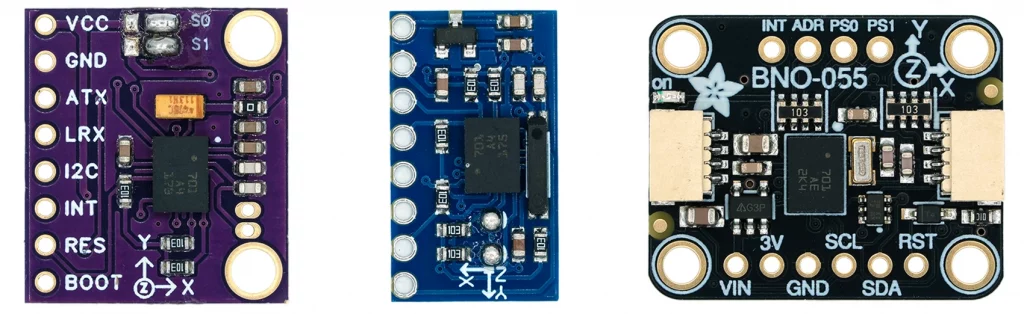
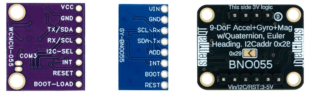
- The external crystal is supplied separately with the left-hand module. You solder it in below “COM3”. The crystals are already soldered on the other modules.
- There are versions of the left module where the solder bridges S0 and S1 (= PS0/PS1, Protocol Select) are not connected as shown above (pulled to GND). To set the I²C protocol, you will have to do this yourself. There is no setting option for this on the middle module. On the Adafruit module, PS0/PS1 are pulled to GND.
- The I²C address pin is pulled to HIGH on the no-name modules (address 0x29), whereas a pull-down resistor is used on the Adafruit module (address 0x28). You can change the address via the address pin (I2C-SEL on the left board). On the Adafruit module, you can alternatively close the solder bridge on the back of the module.
- Only the Adafruit module is 5V-tolerant. It has a voltage regulator and level shifters.
- The Adafruit module is equipped with the practical STEMMA QT connectors (compatible with Qwiic).
The price differences are considerable. If you pay less than 10 euros for the no-name modules, the Adafruit module costs 30 to 40 euros. There is also a high-quality module from DFRobot in a similar price range. Quality and development costs have their price.
Features of the BNO055
You can download the data sheet and other documents here.
Data output
The BNO055 allows you to output the following measured values:
- Acceleration Vector: Acceleration of the module, including gravity
- max. Data rate: 100 Hz, unit: m/s² or mg (= milli-g, not milligram!)
- Linear Acceleration Vector: Acceleration of the module, excluding gravity
- max. Data rate: 100 Hz, unit: m/s² or mg
- Gravity Vector: Only the acceleration due to gravity acting on the module
- max. Data rate: 100 Hz, unit: m/s² or mg
- Angular Velocity Vector
- max. Data rate: 100 Hz, unit: rad/s or °/s
- Magnetic Field Strength Vector
- max. Data rate: 20 Hz, unit: µTesla
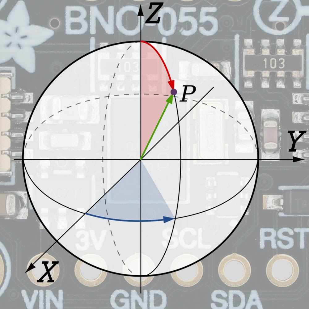
- Absolute Orientation
- As quaternion
- max. Data rate: 100 Hz, unit: none
- As Euler Angles
- max. Data rate: 100 Hz, unit: ° or rad
- As quaternion
- Temperature
- max. Data rate: 1 Hz, unit: °C or °F
Euler angles describe the absolute orientation in space by the yaw (heading), pitch and roll angles. Quaternions are mathematical constructs that circumvent certain problems of Euler angles, such as the gimbal lock.
Fusion and non-fusion modes
The magnetometer, the gyroscope and the magnetometer are the actual sensors of the BNO055. The great thing about the BNO055 is that it can combine their data to calculate the absolute orientation in space or to separate the acceleration due to gravity from the acceleration due to movement (linear acceleration). You can obtain the combined values in the so-called fusion modes. If you just want the bare sensor data, you can use the non-fusion modes. Here is an overview of all modes:
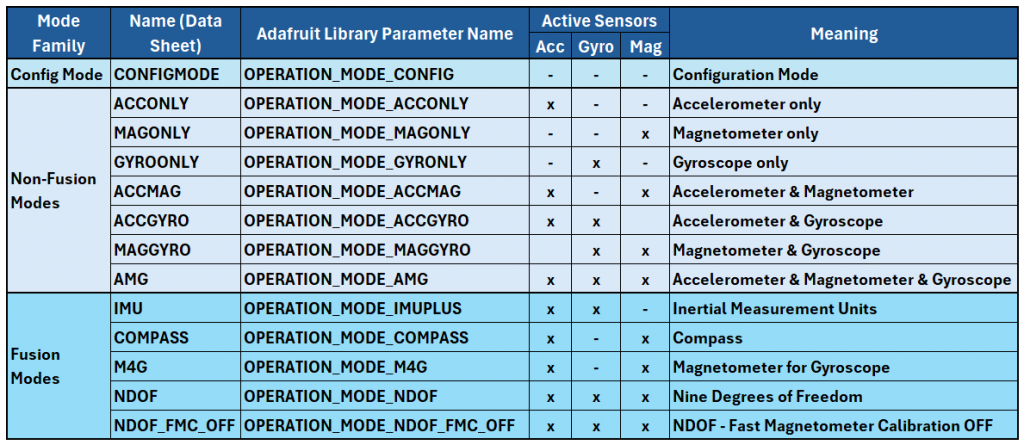
The non-fusion modes should be self-explanatory. A few comments on the fusion modes:
- IMU (Inertial Measurement Unit): Uses accelerometer and gyroscope, i.e. the “real” IMUs.
- Fast, but only relative orientation.
- COMPASS: Uses the x and y axes of the magnetometer and the accelerometer to determine the position of the magnetometer.
- Absolute orientation, but data reliability can be impaired by interfering magnetic fields.
- M4G (Magnet for Gyroscope): Accelerometer and magnetometer; without calibration of the magnetometer.
- Like IMU, but with magnetometer instead of gyroscope. Absolute orientation, lower power consumption than IMU but susceptible to interfering magnetic fields.
- NDOF (Nine Degrees of Freedom): All sensors, with fast calibration of the magnetometer.
- The most accurate and fastest method, but with the highest power consumption.
- NDOF_FMC_OFF (NDOF – Fast Magnetometer Calibration Off): Like NDOF, but with slow calibration of the magnetometer.
- Slightly lower power consumption than NDOF.
NDOF is the default mode when using the Adafruit library.
Key electrical characteristics
- Power supply: 2.4 – 3.6 volts (Adafruit module: 5 volts also possible)
- Typical start-up/reset times:
- Reset (reset to config mode): 650 ms
- Start-up: 400 ms
- Power consumption (self-determined in NDOF mode):
- Normal mode: 12.9 mA
- Suspend mode: 1.2 mA
- Low power mode: 12.9 mA (active phase) / 1.9 mA (power-saving phase)
- The low power mode is not implemented in the Adafruit library (as of Feb. 2026)
Properties of the sensors
The sensors have a wide range of possible settings:
- Accelerometer:
- Range: ± 2 g, ± 4 g, ± 8 g, ± 16 g
- Bandwidth: 7.81 Hz, 15.63 Hz, 31.25 Hz, 62.5 Hz, 125 Hz, 250 Hz, 500 Hz, 1000 Hz
- Power modes: Normal, Suspend, Low Power 1, Low Power 2, Standby, Deep Suspend
- Gyroscope:
- Range: ± 125 °/s, ± 250 °/s, ± 500 °/s, ± 1000 °/s, ± 2000 °/s
- Bandwidth: 12 Hz, 23 Hz, 32 Hz, 47 Hz, 64 Hz, 116 Hz, 230 Hz, 523 Hz
- Power modes: Normal, Fast Power Up, Deep Suspend, Suspend, Advanced Powersave
- Magnetometer:
- Range (typical values): ± 1300 µT, ± 2500 µT
- Data rate: 2 Hz, 6 Hz, 8 Hz, 10 Hz, 15 Hz, 20 Hz, 25 Hz, 30 Hz
- Operational modes: Low Power, Regular, Enhanced Regular, High Accuracy
- Power modes: Normal, Sleep, Suspend, Force Mode
In the accelerometer’s low power mode, the sensor sleeps for an adjustable time between measurements (0.5-1000 milliseconds). The gyroscope has a similar function for the Advanced Powersave Mode (2-20 milliseconds).
Please note: All of these individual sensor settings are only available in non-fusion modes. In Fusion Modes, the settings are made automatically. The Adafruit library has not implemented these settings at all.
Communication
Die Kommunikation mit dem Mikrocontroller ist per I²C oder UART möglich. Allerdings habe ich keine Arduino- bzw. C++-Bibliothek gefunden, die die Ansteuerung per UART implementiert hat. Bezüglich I²C ist einschränkend zu bemerken, dass es mit bestimmten Mikrocontrollern oder I²C-Multiplexern Probleme geben kann (siehe hier auf den Adafruit-Seiten). The maximum I²C clock speed is 400 kHz.
Calibration
In fusion modes, the BNO055 calibrates itself during operation. The calibration status of the sensors is rated on a scale from 0 to 3. The higher the value, the better the calibration and the more reliable the measured values.
For calibration, the BNO055 compares the measured values of the sensors. For example, the gyroscope should output zero for all three axes when at rest. But how can the module know that it is at rest? The answer is: if the accelerometer and the magnetometer deliver constant values. Exactly how the calibration works, however, is the manufacturer’s trade secret.
The offsets resulting from the calibration are saved to the relevant offset registers. They can be read from there and written back at the next start so that you do not have to wait for the calibration again.
In addition to the calibration status of the sensors, there is also a system calibration status. This refers to sensor fusion and is therefore specific to the operating mode.
Interrupts
I could easily write a separate article about the interrupts of the BNO055. Instead, you’ll have to make do with a brief overview. The example sketches will certainly make things clearer. Otherwise, please refer to the data sheet, chapter 3.8.
Accelerometer interrupts
You can set the following interrupts for the accelerometer (but not with the Adafruit library):
- Slow/No-Motion: The slow-motion interrupt is triggered if a certain acceleration slope is exceeded on at least one of the activated axes for a certain number of measured values (max. 64). The no-motion interrupt is triggered if none of the activated axes register an acceleration slope above an adjustable threshold for an adjustable time (max. 336 seconds).
- Any-Motion: The any-motion interrupt is very similar to the slow-motion interrupt, but it is designed to detect short changes in the acceleration slope between two measuring points. To suppress false triggers, you can specify that up to four measurements in a row must exceed the threshold. For further details, please refer to the data sheet (chapters 3.8.2.2 and 3.8.2.3).
- High G: With this interrupt, one of the two trigger criteria is not the slope of the acceleration but exceeding an absolute acceleration value. The other criterion is the adjustable minimum duration of exceeding the threshold.
Gyroscope interrupts
The interrupts of the gyroscope are:
- Any-Motion: The Any Motion interrupt of the gyroscope works in the same way as the Any Motion interrupt of the accelerometer, except that the trigger criterion here is the gradient of the angular velocity.
- High Rate: The high-rate interrupt corresponds to the high-G interrupt of the accelerometer. It is triggered when a specific absolute value of angular velocity is exceeded for a certain period of time.
Connection to the microcontroller
Below you can see a circuit example for controlling the BNO055. I have used a classic Arduino Nano to illustrate two things: Firstly, a level shifter is mandatory for 5 volt boards. Secondly, I would like to emphasize that the BNO055 – unlike the BNO08x family – can also be easily operated with a (comparatively!) small microcontroller.
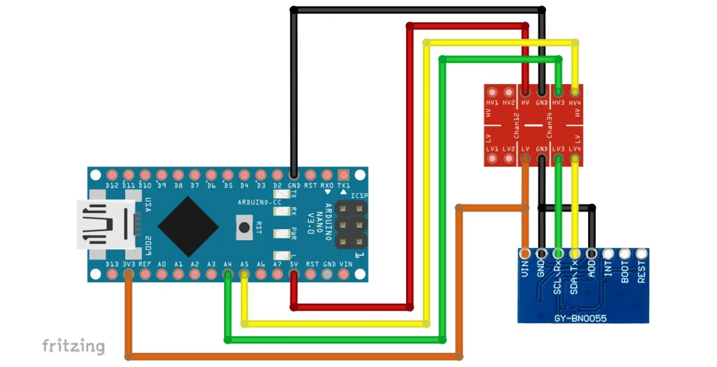
I have left the interrupt, boot, and reset pins unconnected. The boot pin is only relevant if you want to install new firmware. I have not dealt with this. You can connect the reset pin if you intend to perform hardware resets. The reset pin is active-low. We will come to the interrupts later.
Using the Adafruit library
As already mentioned, the Adafruit library is not particularly comprehensive. Among other things, interrupts and individual sensor options for non-fusion modes have not been implemented. However, this will probably not bother many users, because they simply want to retrieve the sensor and sensor fusion data and do not want to deal with complex details or even the data sheet.
A special feature of the Adafruit library is that it also requires the Adafruit_Sensor library. This abstracts sensors and offers a certain degree of convenience. However, this takes you a little further away from the hardware.
Getting started: read_all_data.ino
We will start with the library example sketch “read_all_data.ino”. I have only made two adjustments. Firstly, I adjusted the data rate because I found the output too hectic. Zum anderen habe ich in setup() die Zeile bno.setExtCrystalUse(true); eingefügt, welche – wie der Funktionsname vermuten lässt – die Verwendung des externen Oszillators einstellt.
#include <Wire.h>
#include <Adafruit_Sensor.h>
#include <Adafruit_BNO055.h>
#include <utility/imumaths.h>

/* This driver uses the Adafruit unified sensor library (Adafruit_Sensor),
   which provides a common 'type' for sensor data and some helper functions.

   To use this driver you will also need to download the Adafruit_Sensor
   library and include it in your libraries folder.

   You should also assign a unique ID to this sensor for use with
   the Adafruit Sensor API so that you can identify this particular
   sensor in any data logs, etc.  To assign a unique ID, simply
   provide an appropriate value in the constructor below (12345
   is used by default in this example).

   Connections
   ===========
   Connect SCL to analog 5
   Connect SDA to analog 4
   Connect VDD to 3.3-5V DC
   Connect GROUND to common ground

   History
   =======
   2015/MAR/03  - First release (KTOWN)
*/

/* Set the delay between fresh samples */
uint16_t BNO055_SAMPLERATE_DELAY_MS = 1000;

// Check I2C device address and correct line below (by default address is 0x29 or 0x28)
//                                   id, address
Adafruit_BNO055 bno = Adafruit_BNO055(55, 0x28, &Wire);

void setup(void)
{
  Serial.begin(115200);

  while (!Serial) delay(10);  // wait for serial port to open!

  Serial.println("Orientation Sensor Test"); Serial.println("");

  /* Initialise the sensor */
  if (!bno.begin())
  {
    /* There was a problem detecting the BNO055 ... check your connections */
    Serial.print("Ooops, no BNO055 detected ... Check your wiring or I2C ADDR!");
    while (1);
  }

  bno.setExtCrystalUse(true); // this line is not in the original example sketch

  delay(1000);
}

void loop(void)
{
  //could add VECTOR_ACCELEROMETER, VECTOR_MAGNETOMETER,VECTOR_GRAVITY...
  sensors_event_t orientationData , angVelocityData , linearAccelData, magnetometerData, accelerometerData, gravityData;
  bno.getEvent(&orientationData, Adafruit_BNO055::VECTOR_EULER);
  bno.getEvent(&angVelocityData, Adafruit_BNO055::VECTOR_GYROSCOPE);
  bno.getEvent(&linearAccelData, Adafruit_BNO055::VECTOR_LINEARACCEL);
  bno.getEvent(&magnetometerData, Adafruit_BNO055::VECTOR_MAGNETOMETER);
  bno.getEvent(&accelerometerData, Adafruit_BNO055::VECTOR_ACCELEROMETER);
  bno.getEvent(&gravityData, Adafruit_BNO055::VECTOR_GRAVITY);

  printEvent(&orientationData);
  printEvent(&angVelocityData);
  printEvent(&linearAccelData);
  printEvent(&magnetometerData);
  printEvent(&accelerometerData);
  printEvent(&gravityData);

  int8_t boardTemp = bno.getTemp();
  Serial.println();
  Serial.print(F("temperature: "));
  Serial.println(boardTemp);

  uint8_t system, gyro, accel, mag = 0;
  bno.getCalibration(&system, &gyro, &accel, &mag);
  Serial.println();
  Serial.print("Calibration: Sys=");
  Serial.print(system);
  Serial.print(" Gyro=");
  Serial.print(gyro);
  Serial.print(" Accel=");
  Serial.print(accel);
  Serial.print(" Mag=");
  Serial.println(mag);

  Serial.println("--");
  delay(BNO055_SAMPLERATE_DELAY_MS);
}

void printEvent(sensors_event_t* event) {
  double x = -1000000, y = -1000000 , z = -1000000; //dumb values, easy to spot problem
  if (event->type == SENSOR_TYPE_ACCELEROMETER) {
    Serial.print("Accl:");
    x = event->acceleration.x;
    y = event->acceleration.y;
    z = event->acceleration.z;
  }
  else if (event->type == SENSOR_TYPE_ORIENTATION) {
    Serial.print("Orient:");
    x = event->orientation.x;
    y = event->orientation.y;
    z = event->orientation.z;
  }
  else if (event->type == SENSOR_TYPE_MAGNETIC_FIELD) {
    Serial.print("Mag:");
    x = event->magnetic.x;
    y = event->magnetic.y;
    z = event->magnetic.z;
  }
  else if (event->type == SENSOR_TYPE_GYROSCOPE) {
    Serial.print("Gyro:");
    x = event->gyro.x;
    y = event->gyro.y;
    z = event->gyro.z;
  }
  else if (event->type == SENSOR_TYPE_ROTATION_VECTOR) {
    Serial.print("Rot:");
    x = event->gyro.x;
    y = event->gyro.y;
    z = event->gyro.z;
  }
  else if (event->type == SENSOR_TYPE_LINEAR_ACCELERATION) {
    Serial.print("Linear:");
    x = event->acceleration.x;
    y = event->acceleration.y;
    z = event->acceleration.z;
  }
  else if (event->type == SENSOR_TYPE_GRAVITY) {
    Serial.print("Gravity:");
    x = event->acceleration.x;
    y = event->acceleration.y;
    z = event->acceleration.z;
  }
  else {
    Serial.print("Unk:");
  }

  Serial.print("\tx= ");
  Serial.print(x);
  Serial.print(" |\ty= ");
  Serial.print(y);
  Serial.print(" |\tz= ");
  Serial.println(z);
}
Here is the output of the sketch on the serial monitor:

Explanations for read_all_data.ino
I will not go through every line. Much of it should be self-explanatory.
Use Adafruit_BNO055 bno = Adafruit_BNO055(55, 0x28, &Wire) to create your BNO055 object. Pass a sensor ID, the I²C address, and the TwoWire object (as a reference). The sensor ID is a feature of the Adafruit sensor library and can be freely selected (data type: int32_t).
You initialize your module with bno.begin(). The return value (bool) tells you whether the initialization was successful.
The measurement data of the BNO055 is stored in structures of type sensors_event_t. The definition of the structure can be found in Adafruit_Sensor.h. You query the measured values with getEvent(&xxxxxData, Adafruit_BNO055::VECTOR_XXXXX), where xxxxx or XXXXX stand for the respective sensor or sensor fusion. An exception is the temperature, which you query using bno.getTemp().
You output the measurement data with printEvent(&xxxxxData). The function uses the event type to recognize which sensor the data comes from or whether it is a calculated sensor fusion value. As the event is passed as a reference to printEvent(), you must use the arrow operator instead of the point operator if you want to access the respective axis values. For example, z = event->orientation.z.
Incidentally, the “events” here are a concept from the Adafruit_Sensor library. This has nothing to do with the event concept you may be familiar with from BNO08x.
Calibration
In addition to the measurement data, the sketch also displays the calibration status. When you restart or reset the BNO055, you will see that all calibration status values are initially zero. The calibration status of the gyroscope quickly changes to 3. To calibrate the magnetometer, you have to rotate the BNO055 slightly around its axes. This is quick in NDOF mode, but takes a little longer in the other modes. Calibrating the accelerometer takes the longest. The data sheet recommends placing the BNO055 in 6 different orientations for a few seconds.
Further settings and functions
The Adafruit library offers further setting options and functions, some of which have their own example sketches.
Setting the fusion or non-fusion mode
The default setting, namely NDOF mode, is applied in the read_all_data.ino sketch. There are two ways to change the mode. You pass the mode to:
- the function
begin() - or to
setMode()
The name of the parameter for the mode you want to select can be found in the table above.
Querying and setting the calibration values
As you have seen, calibration takes a certain amount of time. To save time after a reset or restart, you can query the offsets with getSensorOffsets(), save them in the EEPROM (if available) and write them back with setSensorOffsets() after the reset or restart. The function isFullyCalibrated() is also very useful in this context. It checks, depending on the mode, whether the sensors used have calibration status 3.
I will not go into this in detail, as there is an example sketch restore_offsets.ino that illustrates the use of these functions.
System status / Sensor information
The example sketch sensor_api.ino provides you with information about the sensor from the Adafruit sensor library, such as the sensor name and the ID you have assigned. The sketch also provides information about the system status, the result of the self-test, and any system errors:
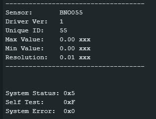
The “System Status” is the content of the system status register. You can find out how to interpret the number in the data sheet in section 4.3.58.
“Self Test” is the content of the self-test register (see section 4.3.55). A “1” means success, a “0” means error.
- Bit0 stands for the accelerometer
- Bit1 stands for the magnetometer
- Bit3 stands for the gyroscope
- Bit4 stands for the microcontroller of the BNO055
Example: Self-test register is 0xF = 0b1111 ⇒ everything is OK.
“System Error” is the content of the system error register. You can find the “translation” in the data sheet in section 4.3.59. If you receive 0x0, everything is OK.
Axis Remap
To remap the axes, for example to swap the x-axis with the z-axis, you can use the function setAxisRemap(REMAP_CONFIG_Px). Here, x is a number between 0 and 7 and stands for a specific mounting position of the module. You will find schematic illustrations in the data sheet in chapter 3.4.
If the variants are not sufficient for you, you can also create the appropriate parameter for setAxisMap() yourself. To do this, we look at the AXIS_MAP_CONFIG register, which the function writes to:
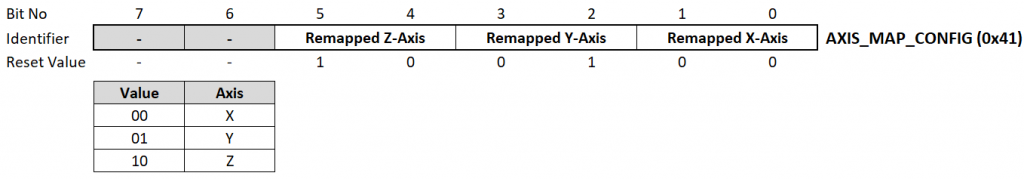
The reset value is 0b100100 = 0x24. To make the z-axis the x-axis, you write 0b00 (representing the x-axis) in bits 4 and 5. To make the x-axis the z-axis, you write 0xb10 (representing the z-axis) in bits 0 and 1. The register content is then 0b000110 = 0x6, so your function call would be setAxisRemap(0x6). I have found that setAxisRemap() may not be called at any point. It is best to use the function directly after bno.begin().
Changing axis signs
Perhaps you have installed the BNO055 so that the z-axis is pointing downwards? Depending on whether you have rotated it around the x-axis or the y-axis, the sign of the z-axis and the x-axis or the z-axis and the y-axis will be reversed. You can easily change the sign with setAxisSign(REMAP_SIGN_Px). P0 to P7 again stand for the mounting positions just mentioned.
Alternatively, you can calculate the parameter yourself. The function writes to the AXIS_MAP_SIGN register:
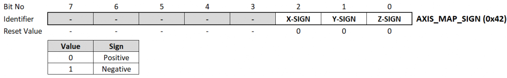
The default value is 0. To reverse the z-axis sign, bit0 must be one, i.e. setAxisSign(0x1). If you want to change the signs of the z- and x-axis, write 0b101 = 0x5 to the register, i.e. setAxisSign(0x5). It is also best to make this setting directly after bno.begin() .
Raw Data
If you do not wish to use the Adafruit Unified Sensor System, you can use the so-called raw data helper functions. One reason for this could be that you want to access the raw data from the accelerometer, magnetometer, or gyroscope directly before it is processed by the sensor fusion algorithms. The example sketch rawdata.ino shows how this works. Further information can be found here on the Adafruit website.
Suspend mode
If you want to save power, enterSuspendMode() will set the BNO055 into suspend mode. This puts both the sensors and the microcontroller into sleep mode. You can return to normal mode using enterNormalModus(). As already mentioned, the low-power mode is unfortunately not implemented, although it is actually very useful. In low-power mode, the BNO055 goes into an energy-saving state after a certain time without activity (default setting is 5 seconds), in which only the accelerometer is active. If the accelerometer registers activity, the BNO055 returns to normal mode until the next inactive phase.
Using the DFRobot library
The Adafruit library will probably satisfy the needs of many users. However, it does not fully cover the potential of the BNO055. The DFRobot_BNO055 library is much more comprehensive but also more complex.
Unfortunately, you cannot install the library via the library manager of the Arduino IDE. Instead, follow the link above, click on the green button ” Code”, and then on “Download ZIP”. Save the file and unzip it in your Arduino/libraries folder. You should then see a subfolder “DFRobot_BNO055-master” containing the library files. You can then open the example sketches via the Arduino IDE under File → Examples → DFRobot_BNO055-master.
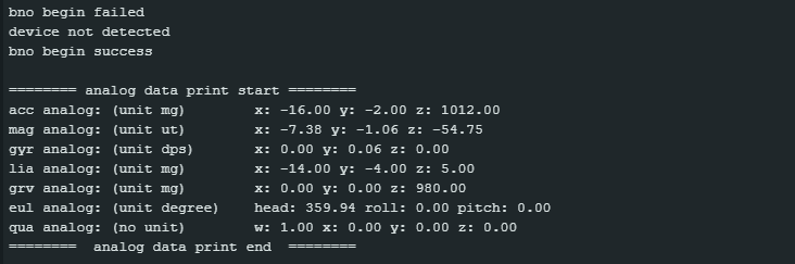
Getting started – readData.ino
/*!
  * read_data.ino
  *
  * Download this demo to test read data from bno055
  * Data will print on your serial monitor
  *
  * Product: http://www.dfrobot.com.cn/goods-1860.html
  * Copyright   [DFRobot](http://www.dfrobot.com), 2016
  * Copyright   GNU Lesser General Public License
  *
  * version  V1.0
  * date  07/03/2019
  */

#include "DFRobot_BNO055.h"
#include "Wire.h"

typedef DFRobot_BNO055_IIC    BNO;    // ******** use abbreviations instead of full names ********

BNO   bno(&Wire, 0x28);    // input TwoWire interface and IIC address

// show last sensor operate status
void printLastOperateStatus(BNO::eStatus_t eStatus)
{
  switch(eStatus) {
  case BNO::eStatusOK:   Serial.println("everything ok"); break;
  case BNO::eStatusErr:  Serial.println("unknow error"); break;
  case BNO::eStatusErrDeviceNotDetect:   Serial.println("device not detected"); break;
  case BNO::eStatusErrDeviceReadyTimeOut:    Serial.println("device ready time out"); break;
  case BNO::eStatusErrDeviceStatus:    Serial.println("device internal status error"); break;
  default: Serial.println("unknow status"); break;
  }
}

void setup()
{
  Serial.begin(115200);
  bno.reset();  // resets the BNO055
  while(bno.begin() != BNO::eStatusOK) {
    Serial.println("bno begin failed");
    printLastOperateStatus(bno.lastOperateStatus);
    delay(2000);
  }
  Serial.println("bno begin success");
}

#define printAxisData(sAxis) \
  Serial.print(" x: "); \
  Serial.print(sAxis.x); \
  Serial.print(" y: "); \
  Serial.print(sAxis.y); \
  Serial.print(" z: "); \
  Serial.println(sAxis.z)

void loop()
{
  BNO::sAxisAnalog_t   sAccAnalog, sMagAnalog, sGyrAnalog, sLiaAnalog, sGrvAnalog;
  BNO::sEulAnalog_t    sEulAnalog;
  BNO::sQuaAnalog_t    sQuaAnalog;
  sAccAnalog = bno.getAxis(BNO::eAxisAcc);    // read acceleration
  sMagAnalog = bno.getAxis(BNO::eAxisMag);    // read geomagnetic
  sGyrAnalog = bno.getAxis(BNO::eAxisGyr);    // read gyroscope
  sLiaAnalog = bno.getAxis(BNO::eAxisLia);    // read linear acceleration
  sGrvAnalog = bno.getAxis(BNO::eAxisGrv);    // read gravity vector
  sEulAnalog = bno.getEul();                  // read euler angle
  sQuaAnalog = bno.getQua();                  // read quaternion
  Serial.println();
  Serial.println("======== analog data print start ========");
  Serial.print("acc analog: (unit mg)       "); printAxisData(sAccAnalog);
  Serial.print("mag analog: (unit ut)       "); printAxisData(sMagAnalog);
  Serial.print("gyr analog: (unit dps)      "); printAxisData(sGyrAnalog);
  Serial.print("lia analog: (unit mg)       "); printAxisData(sLiaAnalog);
  Serial.print("grv analog: (unit mg)       "); printAxisData(sGrvAnalog);
  Serial.print("eul analog: (unit degree)   "); Serial.print(" head: "); Serial.print(sEulAnalog.head); Serial.print(" roll: "); Serial.print(sEulAnalog.roll);  Serial.print(" pitch: "); Serial.println(sEulAnalog.pitch);
  Serial.print("qua analog: (no unit)       "); Serial.print(" w: "); Serial.print(sQuaAnalog.w); printAxisData(sQuaAnalog);
  Serial.println("========  analog data print end  ========");

  delay(1000);
}
The line typedef DFRobot_BNO055_IIC BNO; is for convenience only. It allows you to use “BNO” instead of the long library name “DFRobot_BNO055_IIC”. With BNO bno(&Wire, 0x28); you create your BNO055 object and pass it the I²C object Wire and the I²C address.
while(bno.begin() != BNO::eStatusOK) tries to initialize the BNO055 until it returns that everything is OK. For beginners, the double colon notation may not be familiar. eStatusOK is defined in the enum eStatus_t in DFRobot_BNO055.h. Since the enum definition is inside the class, you must prefix the class name with the double colon. The disadvantage is more typing; the advantage is protection against name collisions.
The measured values are stored in structures of type sAxisAnalog_t, sEulAnalog_t and sQuaAnalog_t. These definitions can also be found in DFRobot_BNO055.h. x, y and z values are queried with getAxis(). Since the function takes different measured values, you still need to pass the type, e.g. BNO::eAxisAcc for the accelerometer. getEul() and getQua(), on the other hand, are unambiguous.
If you want to write an output function for the measured values, you will face the problem that it has to accept different value types (sAccAnalog, sMagAnalog etc.). In readData.ino, the problem is solved with a #define macro (problems with this? See here).
The rest should be clear, right? Here is the output:
Extending sketches with functions
If you want to add functions to the example sketches that are not described in the example sketches, you will have to dig around a bit in DFRobot_BNO055.h. On the one hand, you need the function names, and on the other hand, often you need the data type that is passed or returned.
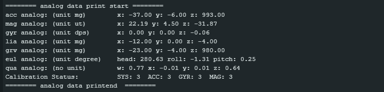
In the following modified version of readData.ino, I show this using the calibration status as an example. The function is getCalStatus() and the return value is a structure of type sRegCalibState.
/*!
  * read_data.ino
  *
  * Download this demo to test read data from bno055
  * Data will print on your serial monitor
  *
  * Product: http://www.dfrobot.com.cn/goods-1860.html
  * Copyright   [DFRobot](http://www.dfrobot.com), 2016
  * Copyright   GNU Lesser General Public License
  *
  * version  V1.0
  * date  07/03/2019
  * modified by Wolfgang Ewald 07/02/2026
  */

#include "DFRobot_BNO055.h"
#include "Wire.h"

typedef DFRobot_BNO055_IIC    BNO;    // ******** use abbreviations instead of full names ********

BNO   bno(&Wire, 0x28);    // input TwoWire interface and IIC address

// show last sensor operate status
void printLastOperateStatus(BNO::eStatus_t eStatus)
{
  switch(eStatus) {
  case BNO::eStatusOK:   Serial.println("everything ok"); break;
  case BNO::eStatusErr:  Serial.println("unknow error"); break;
  case BNO::eStatusErrDeviceNotDetect:   Serial.println("device not detected"); break;
  case BNO::eStatusErrDeviceReadyTimeOut:    Serial.println("device ready time out"); break;
  case BNO::eStatusErrDeviceStatus:    Serial.println("device internal status error"); break;
  default: Serial.println("unknow status"); break;
  }
}

void setup()
{
  Serial.begin(115200);
  bno.reset();
  delay(1000); // give time to reset and avoid "device not detected"
  while(bno.begin() != BNO::eStatusOK) {
    Serial.println("bno begin failed");
    printLastOperateStatus(bno.lastOperateStatus);
    delay(2000);
  }
  Serial.println("bno begin success");
}

#define printAxisData(sAxis) \
  Serial.print(" x: "); \
  Serial.print(sAxis.x); \
  Serial.print(" y: "); \
  Serial.print(sAxis.y); \
  Serial.print(" z: "); \
  Serial.println(sAxis.z)

void loop()
{
  BNO::sAxisAnalog_t   sAccAnalog, sMagAnalog, sGyrAnalog, sLiaAnalog, sGrvAnalog;
  BNO::sEulAnalog_t    sEulAnalog;
  BNO::sQuaAnalog_t    sQuaAnalog;
  BNO::sRegCalibState_t sCalibState;
  sAccAnalog = bno.getAxis(BNO::eAxisAcc);    // read acceleration
  sMagAnalog = bno.getAxis(BNO::eAxisMag);    // read geomagnetic
  sGyrAnalog = bno.getAxis(BNO::eAxisGyr);    // read gyroscope
  sLiaAnalog = bno.getAxis(BNO::eAxisLia);    // read linear acceleration
  sGrvAnalog = bno.getAxis(BNO::eAxisGrv);    // read gravity vector
  sEulAnalog = bno.getEul();                  // read euler angle
  sQuaAnalog = bno.getQua();                  // read quaternion
  sCalibState = bno.getCalStatus();           // read calibration status
  Serial.println();
  Serial.println("======== analog data print start ========");
  Serial.print("acc analog: (unit mg)       "); printAxisData(sAccAnalog);
  Serial.print("mag analog: (unit ut)       "); printAxisData(sMagAnalog);
  Serial.print("gyr analog: (unit dps)      "); printAxisData(sGyrAnalog);
  Serial.print("lia analog: (unit mg)       "); printAxisData(sLiaAnalog);
  Serial.print("grv analog: (unit mg)       "); printAxisData(sGrvAnalog);
  Serial.print("eul analog: (unit degree)   "); Serial.print(" head: "); Serial.print(sEulAnalog.head); Serial.print(" roll: "); Serial.print(sEulAnalog.roll);  Serial.print(" pitch: "); Serial.println(sEulAnalog.pitch);
  Serial.print("qua analog: (no unit)       "); Serial.print(" w: "); Serial.print(sQuaAnalog.w); printAxisData(sQuaAnalog);

  Serial.print("Calibration Status:         ");
  Serial.print(" SYS: "); Serial.print(sCalibState.SYS);
  Serial.print("  ACC: "); Serial.print(sCalibState.ACC);
  Serial.print("  GYR: "); Serial.print(sCalibState.GYR);
  Serial.print("  MAG: "); Serial.println(sCalibState.MAG);
  Serial.println("======== analog data printend  ========");

  delay(1000);
}
Here is the output:
Advanced configuration
The example sketch config.ino and my slightly modified version config_mod.ino show how to make some individual settings for the axes and how to set offsets manually. The setting parameters you can choose from can be looked up in DFRobot_BNO055.h.
Even if I repeat myself, these settings can only be made in non-fusion modes. The original version of the example sketch sets the NDOF mode, which renders changed settings ineffective.
/*!
  * config.ino
  *
  * Download this demo to test config to bno055
  * Data will print on your serial monitor
  *
  * Product: http://www.dfrobot.com.cn/goods-1860.html
  * Copyright   [DFRobot](http://www.dfrobot.com), 2016
  * Copyright   GNU Lesser General Public License
  *
  * version  V1.0
  * date  07/03/2019
  * modified by Wolfgang Ewald 12/02/2026
  */

#include "DFRobot_BNO055.h"
#include "Wire.h"

typedef DFRobot_BNO055_IIC    BNO;    // ******** use abbreviations instead of full names ********

BNO   bno(&Wire, 0x28);    // input TwoWire interface and IIC address

// show last sensor operate status
void printLastOperateStatus(BNO::eStatus_t eStatus)
{
  switch(eStatus) {
  case BNO::eStatusOK:    Serial.println("everything ok"); break;
  case BNO::eStatusErr:   Serial.println("unknow error"); break;
  case BNO::eStatusErrDeviceNotDetect:    Serial.println("device not detected"); break;
  case BNO::eStatusErrDeviceReadyTimeOut: Serial.println("device ready time out"); break;
  case BNO::eStatusErrDeviceStatus:       Serial.println("device internal status error"); break;
  default: Serial.println("unknow status"); break;
  }
}

void setup()
{
  Serial.begin(115200);
  bno.reset();
  while(bno.begin() != BNO::eStatusOK) {
    Serial.println("bno begin faild");
    printLastOperateStatus(bno.lastOperateStatus);
    delay(2000);
  }
  Serial.println("bno begin success");

  bno.setPowerMode(BNO::ePowerModeNormal);    // set to normal power mode
  bno.setOprMode(BNO::eOprModeConfig);    // must set sensor to config-mode before configure
  bno.setAccPowerMode(BNO::eAccPowerModeNormal);    // set acc to normal power mode
  bno.setGyrPowerMode(BNO::eGyrPowerModeNormal);    // set gyr to normal power mode
  bno.setMagPowerMode(BNO::eMagPowerModeForce);     // set mag to force power mode

  // accelerometer normal configure
  bno.setAccRange(BNO::eAccRange_2G);   // set range to 2g
  bno.setAccBandWidth(BNO::eAccBandWidth_62_5);   // set band width 62.5HZ
  bno.setAccPowerMode(BNO::eAccPowerModeNormal);  // set accelerometer power mode

  // magnetometer normal configure
  bno.setMagDataRate(BNO::eMagDataRate_20);   // set output data rate 20HZ
  bno.setMagPowerMode(BNO::eMagPowerModeForce);   // set power mode
  bno.setMagOprMode(BNO::eMagOprModeRegular); // set operate mode

  // gyroscope normal configure
  bno.setGyrRange(BNO::eGyrRange_125);   // set range
  bno.setGyrBandWidth(BNO::eGyrBandWidth_32);   // set band width
  bno.setGyrPowerMode(BNO::eGyrPowerModeNormal);    // set power mode

  BNO::sAxisAnalog_t    sOffsetAcc;   // unit mg, members can't out of acc range
  BNO::sAxisAnalog_t    sOffsetMag;   // unit ut, members can't out of mag range
  BNO::sAxisAnalog_t    sOffsetGyr;   // unit dps, members can't out of gyr range
  sOffsetAcc.x = 1;
  sOffsetAcc.y = 1;
  sOffsetAcc.z = 1;
  sOffsetMag.x = 1;
  sOffsetMag.y = 1;
  sOffsetMag.z = 1;
  sOffsetGyr.x = 1;
  sOffsetGyr.y = 1;
  sOffsetGyr.z = 1;
  bno.setAxisOffset(BNO::eAxisAcc, sOffsetAcc);   // set offset
  bno.setAxisOffset(BNO::eAxisMag, sOffsetMag);
  bno.setAxisOffset(BNO::eAxisGyr, sOffsetGyr);

  bno.setOprMode(BNO::eOprModeAMG);   // shift a non-fusion mode
}

#define printAxisData(sAxis) \
  Serial.print(" x: "); \
  Serial.print(sAxis.x); \
  Serial.print(" y: "); \
  Serial.print(sAxis.y); \
  Serial.print(" z: "); \
  Serial.println(sAxis.z)

void loop()
{
  BNO::sAxisAnalog_t   sAccAnalog, sMagAnalog, sGyrAnalog;
  sAccAnalog = bno.getAxis(BNO::eAxisAcc);
  sMagAnalog = bno.getAxis(BNO::eAxisMag);
  sGyrAnalog = bno.getAxis(BNO::eAxisGyr);
  Serial.println();
  Serial.println("======== analog data print start ========");
  Serial.print("acc analog: (unit mg)       "); printAxisData(sAccAnalog);
  Serial.print("mag analog: (unit ut)       "); printAxisData(sMagAnalog);
  Serial.print("gyr analog: (unit dps)      "); printAxisData(sGyrAnalog);
  Serial.println("========  analog data print end  ========");

  delay(1000);
}
Interrupts
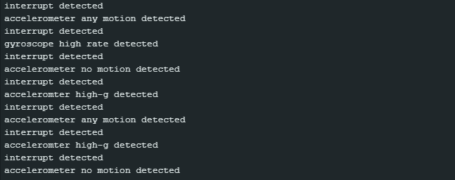
The interrupts of the BNO055 are a rather complex topic. Here is the example sketch interrupt.ino, slightly modified by me:
/*!
  * interrupt.ino
  *
  * Download this demo to test bno055 interrupt
  * Connect bno055 int pin to arduino pin 2
  * If there occurs interrupt, it will printr on you serial monitor, more detail please reference comment
  *
  * Product: http://www.dfrobot.com.cn/goods-1860.html
  * Copyright   [DFRobot](http://www.dfrobot.com), 2016
  * Copyright   GNU Lesser General Public License
  *
  * version  V1.0
  * date  07/03/2019
  */

#include "DFRobot_BNO055.h"
#include "Wire.h"

typedef DFRobot_BNO055_IIC    BNO;    // ******** use abbreviations instead of full names ********

BNO   bno(&Wire, 0x28);    // input TwoWire interface and IIC address

// show last sensor operate status
void printLastOperateStatus(BNO::eStatus_t eStatus)
{
  switch(eStatus) {
  case BNO::eStatusOK:    Serial.println("everything ok"); break;
  case BNO::eStatusErr:   Serial.println("unknow error"); break;
  case BNO::eStatusErrDeviceNotDetect:    Serial.println("device not detected"); break;
  case BNO::eStatusErrDeviceReadyTimeOut: Serial.println("device ready time out"); break;
  case BNO::eStatusErrDeviceStatus:       Serial.println("device internal status error"); break;
  default: Serial.println("unknow status"); break;
  }
}

bool intFlag = false;

void intHandle()
{
  intFlag = true;
}

void setup()
{
  Serial.begin(115200);
  bno.reset();
  while(bno.begin() != BNO::eStatusOK) {
    Serial.println("bno begin faild");
    printLastOperateStatus(bno.lastOperateStatus);
    delay(2000);
  }
  Serial.println("bno begin success");

  bno.setOprMode(BNO::eOprModeConfig);    // set to config mode

  bno.setIntMaskEnable(BNO::eIntAll);    // set interrupt mask enable, signal to int pin when interrupt
  // bno.setIntMaskDisable(BNO::eIntAccAm | BNO::eIntAccNm);    // set interrupt mask disable, no signal to int pin when interrupt

  bno.setIntEnable(BNO::eIntAll);   // set interrupt enable
  // bno.setIntDisable(BNO::eIntAccAm | BNO::eIntAccNm);    // set interrupt disable

  bno.setAccIntEnable(BNO::eAccIntSetAll);    // set accelerometer interrupt enable
  // bno.setAccIntDisable(BNO::eAccIntSetAmnmXAxis | BNO::eAccIntSetHgXAxis);   // set accelerometer interrupt disable

  /* accelerometer any motion threshold to set, unit mg, value is dependent on accelerometer range selected,
   * case 2g, no more than 1991
   * case 4g, no more than 3985
   * case 8g, no more than 7968
   * case 16g, no more than 15937
   * attenion: The set value will be slightly biased according to datasheet
   * tips: default accelerometer range is 4g
   */
  // how to trig this: still --> fast move
  bno.setAccAmThres(100);
  // any motion interrupt triggers if duration consecutive data points are above the any motion interrupt
  // threshold define in any motion threshold
  bno.setAccIntAmDur(1);
  // set high-g duration, value from 2ms to 512ms
  bno.setAccHighGDuration(80);
  /*
   * accelerometer high-g threshold to set, unit mg, value is dependent on accelerometer range selected,
   * case 2g, no more than 1991
   * case 4g, no more than 3985
   * case 8g, no more than 7968
   * case 16g, no more than 15937
   * Attenion: The set value will be slightly biased according to datasheet
   */
  // how to trig this: still --> (very) fast move
  bno.setAccHighGThres(650); // comment Wolfgang: due to a bug the effective value is double the parameter.
  // accelerometer (no motion) / (slow motion) settings, 2nd parameter unit seconds, no more than 336
  bno.setAccNmSet(BNO::eAccNmSmnmNm, 4); // better name would be setAccNmSmSet() for no and slow motion
  /*
   * accelerometer no motion threshold to set, unit mg, value is dependent on accelerometer range selected,
   * case 2g, no more than 1991
   * case 4g, no more than 3985
   * case 8g, no more than 7968
   * case 16g, no more than 15937
   * Attenion: The set value will be slightly biased according to datasheet
   */
  // hot to trig this: any motion --> still --> still
  bno.setAccNmThres(100);

  bno.setGyrIntEnable((BNO::eGyrIntSet_t) (BNO::eGyrIntSetHrXAxis | BNO::eGyrIntSetHrYAxis | BNO::eGyrIntSetHrZAxis));    // set gyroscope interrupt enable, in most cases, this is enough.
  // bno.setGyrIntEnable(BNO::eGyrIntSetAmYAxis | BNO::eGyrIntSetAmYAxis | BNO::eGyrIntSetAmZAxis);    // set gyroscope interrupt enable
  // bno.setGyrIntDisable(BNO::eGyrIntSetHrXAxis | BNO::eGyrIntSetAmXAxis);    // set gyroscope interrupt disable

  /*
   * 2nd parameter, high rate threshold to set, unit degree/seconds, value is dependent on gyroscope range selected,
   * case 2000, no more than 1937
   * case 1000, no more than 968
   * case 500, no more than 484
   * case 250, no more than 242
   * case 125, no more than 121
   * Attenion: The set value will be slightly biased according to datasheet
   * 3rd parameter, high rate duration to set, unit ms, duration from 2.5ms to 640ms
   * Attenion: The set value will be slightly biased according to datasheet
   */
  // how to trigger this: still --> fast tilt
  bno.setGyrHrSet(BNO::eSingleAxisX, 300, 80);
  bno.setGyrHrSet(BNO::eSingleAxisY, 300, 80);
  bno.setGyrHrSet(BNO::eSingleAxisZ, 300, 80);
  /*
   * gyroscope any motion threshold to set, unit mg, value is dependent on accelerometer range selected,
   * case 2000, no more than 128
   * case 1000, no more than 64
   * case 500, no more than 32
   * case 250, no more than 16
   * case 125, no more than 8
   * Attenion: The set value will be slightly biased according to datasheet
   * tips: default range is 2000
   */
  // how to trigger this: still --> fast tilt
  bno.setGyrAmThres(20);

  bno.setOprMode(BNO::eOprModeNdof);    // configure done

  attachInterrupt(digitalPinToInterrupt(2), intHandle, RISING);   // attach interrupt
  bno.getIntState();    // clear unexpected interrupt
  intFlag = false;
}

void loop()
{
  if(intFlag) {
    intFlag = false;
    uint8_t   intSta = bno.getIntState();   // interrupt auto clear after read

    Serial.println("interrupt detected");
    if(intSta & BNO::eIntAccAm)
      Serial.println("accelerometer any motion detected");
    if(intSta & BNO::eIntAccNm)
      Serial.println("accelerometer no motion detected");
    if(intSta & BNO::eIntAccHighG)
      Serial.println("acceleromter high-g detected");
    if(intSta & BNO::eIntGyrHighRate)
      Serial.println("gyroscope high rate detected");
    if(intSta & BNO::eIntGyrAm)
      Serial.println("gyroscope any motion detected");
  }
}
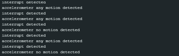
I recommend uploading the sketch and playing around with the module a little. The output could look like this or similar:
To configure interrupts, you must first set the BNO055 to configuration mode.
Activation
With setIntMaskEnable() and setIntMaskDisable() you should be able to set which interrupts are propagated to the interrupt pin. However, in my experience, all activated interrupts are forwarded to the pin, provided that at least one interrupt is set for the interrupt pin. Even if no interrupt is passed to the interrupt pin, the activated interrupts are still triggered, but only the corresponding interrupt flags are set.
The actual (de)activation of the interrupts is done with the function setIntEnable()or setIntDisable(), which works perfectly. The parameters you can choose from are:
- eIntGyrAm: Any-motion for the gyroscope
- eIntGyrHighRate: High-rate for the gyroscope
- eIntAccHighG: High-G for the accelerometer
- eIntAccAm: Any-motion for the accelerometer
- eIntAccNm: No-motion for the accelerometer
- eIntAll: All interrupts
The parameters can also be combined using the logical or (|).
Using setAccIntEnable() or bno.setAccIntDisable(), you can specify which axes trigger the interrupts. Corresponding functions are also available for the gyroscope.
You can set either the no-motion or the slow-motion interrupt, not both. You can do this using the function setAccNmSet(), to which you either pass eAccNmSmnmNm or eAccNmSmnmSm.
Interrupt trigger criteria
Interrupts are triggered when measured values or slopes between the measured values exceed or fall below thresholds for a certain time or a certain number of measured values. The parameters of the following functions define
setAccAmThres(): Threshold for the slope of the acceleration values. The value is actually range-dependent, but the library scales it in the background.setAccHighGThres(): Threshold for the slope of the angular velocities. This value is also range-dependent. The library scales the threshold in the background, but there is still a bug. To correct it, pass the desired threshold divided by 2.setAccNmThres(): This is the slope threshold for the no-/slow-motion interrupt. What complicates matters even more is that the time between two measurement points depends on the bandwidth.setGyrAmThres(): Is the counterpart tosetAccAmThres().setAccNmSet(): We know this function from above. Its second parameter has two different meanings depending on the setting:- No-motion mode: Time in seconds for which the threshold must be undershot (max. 336).
- Slow- motion mode: Number of slope values that must be exceeded. However, this is (currently) not properly implemented in the library.
setGyrHrSet(): Parameter 1 defines the axis, parameter 2 is the limit as an absolute value, parameter 3 is the duration in milliseconds.setAccIntAmDur(): Minimum number of consecutive data points that exceed the threshold before the interrupt is triggered.setAccHighGDuration(): Duration of exceeding the limit in milliseconds before an interrupt is triggered.
Well, are you confused? I certainly was. I have rarely seen such a mishmash of parameters for interrupt settings. The library is not to blame for this!
Low power mode
Let’s move on to something simpler, the low power mode. This is the same sketch as readData_mod.ino, but extended by lines 32 to 37.
#include "DFRobot_BNO055.h"
#include "Wire.h"

typedef DFRobot_BNO055_IIC    BNO;    // ******** use abbreviations instead of full names ********

BNO   bno(&Wire, 0x28);    // input TwoWire interface and IIC address

// show last sensor operate status
void printLastOperateStatus(BNO::eStatus_t eStatus)
{
  switch(eStatus) {
  case BNO::eStatusOK:   Serial.println("everything ok"); break;
  case BNO::eStatusErr:  Serial.println("unknow error"); break;
  case BNO::eStatusErrDeviceNotDetect:   Serial.println("device not detected"); break;
  case BNO::eStatusErrDeviceReadyTimeOut:    Serial.println("device ready time out"); break;
  case BNO::eStatusErrDeviceStatus:    Serial.println("device internal status error"); break;
  default: Serial.println("unknow status"); break;
  }
}

void setup()
{
  Serial.begin(115200);
  bno.reset();
  delay(1000);
  while(bno.begin() != BNO::eStatusOK) {
    Serial.println("bno begin faild");
    printLastOperateStatus(bno.lastOperateStatus);
    delay(2000);
  }
  Serial.println("bno begin success");
  bno.setOprMode(BNO::eOprModeConfig);
  // bno.setAccAmThres(500); // relvant for wakeup
  // bno.setAccIntAmDur(1);  // relevant for wakeup
  // bno.setAccNmThres(100);  // relevant for entering low power mode
  // bno.setAccNmSet(BNO::eAccNmSmnmNm, 4); // relevant for entering low power mode
  bno.setPowerMode(BNO::ePowerModeLowPower);
  bno.setOprMode(BNO::eOprModeNdof);
}

#define printAxisData(sAxis) \
  Serial.print(" x: "); \
  Serial.print(sAxis.x); \
  Serial.print(" y: "); \
  Serial.print(sAxis.y); \
  Serial.print(" z: "); \
  Serial.println(sAxis.z)

void loop()
{
  BNO::sAxisAnalog_t   sAccAnalog, sMagAnalog, sGyrAnalog, sLiaAnalog, sGrvAnalog;
  BNO::sEulAnalog_t    sEulAnalog;
  BNO::sQuaAnalog_t    sQuaAnalog;
  BNO::sRegCalibState_t sCalibState;
  sAccAnalog = bno.getAxis(BNO::eAxisAcc);    // read acceleration
  sMagAnalog = bno.getAxis(BNO::eAxisMag);    // read geomagnetic
  sGyrAnalog = bno.getAxis(BNO::eAxisGyr);    // read gyroscope
  sLiaAnalog = bno.getAxis(BNO::eAxisLia);    // read linear acceleration
  sGrvAnalog = bno.getAxis(BNO::eAxisGrv);    // read gravity vector
  sEulAnalog = bno.getEul();                  // read euler angle
  sQuaAnalog = bno.getQua();                  // read quaternion
  sCalibState = bno.getCalStatus();           // read calibration status
  Serial.println();
  Serial.println("======== analog data print start ========");
  Serial.print("acc analog: (unit mg)       "); printAxisData(sAccAnalog);
  Serial.print("mag analog: (unit ut)       "); printAxisData(sMagAnalog);
  Serial.print("gyr analog: (unit dps)      "); printAxisData(sGyrAnalog);
  Serial.print("lia analog: (unit mg)       "); printAxisData(sLiaAnalog);
  Serial.print("grv analog: (unit mg)       "); printAxisData(sGrvAnalog);
  Serial.print("eul analog: (unit degree)   "); Serial.print(" head: "); Serial.print(sEulAnalog.head); Serial.print(" roll: "); Serial.print(sEulAnalog.roll);  Serial.print(" pitch: "); Serial.println(sEulAnalog.pitch);
  Serial.print("qua analog: (no unit)       "); Serial.print(" w: "); Serial.print(sQuaAnalog.w); printAxisData(sQuaAnalog);

  Serial.print("Calibration Status:         ");
  Serial.print(" SYS: "); Serial.print(sCalibState.SYS);
  Serial.print("  ACC: "); Serial.print(sCalibState.ACC);
  Serial.print("  GYR: "); Serial.print(sCalibState.GYR);
  Serial.print("  MAG: "); Serial.println(sCalibState.MAG);
  Serial.println("======== analog data printend  ========");

  delay(1000);
}
After a few seconds of runtime, you will see that the output values are frozen. This indicates that the BNO055 is in low power mode. If you move the module a little, it will wake up again. The conditions for sleeping and waking up are the same as for the no-motion and any-motion interrupts. To test this, you can uncomment lines 33 to 36 and play around with the parameters.
Further settings and comments
You can remap the axes and set the axis signs using setAxisMapConfig() and setAxisMapSign(). The parameters are eMapSign_Px and eMapConfig_Px with x = 0 to 7. As already mentioned in the Adafruit library, P0 to P7 correspond to specific mounting positions of the BNO055, which are described in section 3.4 of the data sheet.
What the library does not seem to have implemented is the setting of the sleep times for the accelerometer and the gyroscope in the sensor-specific low power mode or advanced power mode.
Using the Bosch library
Finally, I would like to discuss the BNO055 library from sensor manufacturer Bosch. You can find it here on GitHub. Installation is easy via the Arduino IDE library manager.
The library is written in C style and may therefore take some time to get used to for less experienced users. For example, you do not create a BNO055 object, as the library does not contain a class. Accordingly, you do not call the functions as usual via objectname.function_name(), but only via the function name, such as bno055_read_accel_xyz().
Another feature of the library is that you cannot avoid looking at the data sheet and the library files. For example, if you want to set the thresholds for the interrupts, you first have to find the function name, as there are few example sketches. Then you have to find out the meaning of the parameters to be passed.
That all sounds a bit deterrent, but the advantage of this library is its completeness. It gives you maximum control. And it’s not rocket science to use either; it just requires a little more familiarization and looking things up. My example sketches may help you get started.
How to make settings and read measured data
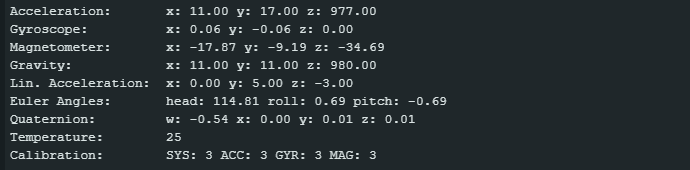
The library only has one example sketch that illustrates the reading of measured values, namely Euler_Streaming.ino. As it only provides Euler angles, I have extended it to include the other measured values and the calibration status.
I will also show you examples of how to configure some settings. You will need to find additional configuration functions and the associated parameters yourself in BNO055.h.
#include "BNO055_support.h"		//Contains the bridge code between the API and Arduino
#include <Wire.h>

//The device address is set to BNO055_I2C_ADDR2 in this example. You can change this in the BNO055.h file in the code segment shown below.
// /* bno055 I2C Address */
// #define BNO055_I2C_ADDR1                0x28
// #define BNO055_I2C_ADDR2                0x29
// #define BNO055_I2C_ADDR                 BNO055_I2C_ADDR2

//This structure contains the details of the BNO055 device that is connected. (Updated after initialization)
struct bno055_t myBNO;

// Structures to hold the measured/calculated data
struct bno055_accel myAccelData;
struct bno055_gyro myGyroData;
struct bno055_mag myMagData;
struct bno055_euler myEulerData;
struct bno055_quaternion myQuaternionData;
struct bno055_linear_accel myLinearAccelData;
struct bno055_gravity myGravityData;

BNO055_S16 myTemperatureData; // BNO055_S16 = short int

int factor = 1.0;  // for calculation measured values from raw data

void setup() {
  //Initialize I2C communication
  Wire.begin();

  //Initialization of the BNO055
  BNO_Init(&myBNO); // Assigning the structure to hold information about the device

  /* Some config examples. After initiation you are in config mode, for later changes go
     into config mode before. If you apply changes, you need to repower the BNO055 or do
     a reset. */
  bno055_set_reset_sys(1); delay(800); // force reset a give rest time
  /* Some examples of config options */
  // bno055_set_operation_mode(OPERATION_MODE_CONFIG);  // change to config mode
  // bno055_set_powermode(POWER_MODE_LOW_POWER); // Altern.:  POWER_MODE_SUSPEND / POWER_MODE_LOW_POWER
  // bno055_set_axis_remap_value(REMAP_Y_Z); // swap y and z axis
  // bno055_set_x_remap_sign(1);  // set negative sign for x-axis
  // bno055_set_accel_range(ACCEL_RANGE_2G); // not available in fusion modes
  // bno055_set_gyro_range(GYRO_RANGE_125rps);  // you also need to change the factor below; not available in fusion modes
  bno055_set_operation_mode(OPERATION_MODE_NDOF); //  set NDoF mode

  delay(1);

  //Initialize the Serial Port to view information on the Serial Monitor
  Serial.begin(115200);
}

template <typename T>
void printXYZ(const T *xyzData, float factor) {
  Serial.print(" x: "); Serial.print((float)xyzData->x / factor);
  Serial.print(" y: "); Serial.print((float)xyzData->y / factor);
  Serial.print(" z: "); Serial.println((float)xyzData->z / factor);
}

void printCalib() {
  unsigned char sysCalib=99, accelCalib=99, gyroCalib=99, magCalib=99;
  bno055_get_syscalib_status(&sysCalib);
  bno055_get_accelcalib_status(&accelCalib);
  bno055_get_gyrocalib_status(&gyroCalib);
  bno055_get_magcalib_status(&magCalib);
  Serial.print("Calibration:        ");
  Serial.print("SYS: "); Serial.print(sysCalib);
  Serial.print(" ACC: "); Serial.print(accelCalib);
  Serial.print(" GYR: "); Serial.print(gyroCalib);
  Serial.print(" MAG: "); Serial.println(magCalib);
}

void loop() {

  bno055_read_accel_xyz(&myAccelData);
  bno055_read_gyro_xyz(&myGyroData);
  bno055_read_mag_xyz(&myMagData);
  bno055_read_gravity_xyz(&myGravityData);
  bno055_read_linear_accel_xyz(&myLinearAccelData);
  bno055_read_euler_hrp(&myEulerData);
  bno055_read_quaternion_wxyz(&myQuaternionData);
  bno055_read_temperature_data(&myTemperatureData);

  Serial.print("Acceleration:      "); printXYZ(&myAccelData, 1.0);
  Serial.print("Gyroscope:         "); printXYZ(&myGyroData, 16.0);
  Serial.print("Magnetometer:      "); printXYZ(&myMagData, 16.0);
  Serial.print("Gravity:           "); printXYZ(&myGravityData, 1.0);
  Serial.print("Lin. Acceleration: "); printXYZ(&myLinearAccelData, 1.0);
  Serial.print("Euler Angles:      ");
  Serial.print(" head: "); Serial.print((float)myEulerData.h / 16.0);
  Serial.print(" roll: "); Serial.print((float)myEulerData.r / 16.0);
  Serial.print(" pitch: "); Serial.println((float)myEulerData.p / 16.0);
  Serial.print("Quaternion:        "); Serial.print(" w: "); Serial.print((float)myQuaternionData.w / 16384.0);
  printXYZ(&myQuaternionData, 16384.0);
  Serial.print("Temperature:        "); Serial.println(myTemperatureData);
  printCalib();

  Serial.println();					//Extra line to differentiate between packets

  delay(1000);
}
This is what the output on the serial monitor looks like:
I don’t want to go through the sketch line by line, but I would like to give you a few hints that go beyond the comments in the sketch:
- As there is no class with a constructor, you cannot pass an I²C address. You must make changes directly in BNO055.h.
- The structure myBNO contains device information (see example sketch Basic.ino) and is required for the init function.
- The measured values are stored in structures. You pass these structures to the responsible functions as references.
- The measured values are returned as raw data, which still needs to be converted using individual factors. It is important to note that the factor for the gyroscope values is range-dependent.
- Different data types are passed to the output function
printXYZ()for the measured values. In previous sketches, we circumvented the problem with a#definemacro. Instead, I opted for a solution using a template.
Interrupts
As a hopefully useful addition to the few example sketches in the library, I have written another sketch that should give you a better understanding of how to use interrupts. I have limited myself to the any-motion and no-(/slow-)motion interrupts. If you want to set up further interrupts, you must select the appropriate functions from BNO055.h.
Here is the sketch:
#include "BNO055_support.h"    //Contains the bridge code between the API and Arduino
#include <Wire.h>
#define FUNC_ENABLE 1  // enable functions
#define FUNC_DISABLE 0 // disable functions
#define NO_MOTION_ENABLE 1
#define SLOW_MOTION_ENABLE 0

//This structure contains the details of the BNO055 device that is connected. (Updated after initialization)
struct bno055_t myBNO;

int intPin = 2;  // interrupt pin
unsigned char intSta = 0; // interupt status register
volatile bool intFlag = false;  // interrupt flag

void intHandle() {
  intFlag = true;
}

void setup() {
  //Initialize I2C communication
  Wire.begin();
  pinMode(intPin, INPUT);

  //Initialization of the BNO055
  BNO_Init(&myBNO); //Assigning the structure to hold information about the device

  /* Some config examples. After iniitiation you are in config mode, for later changes go
     into config mode before. If you apply changes, you need to repower the BNO055 or do
     a reset. */
  bno055_set_reset_sys(true); delay(800); // force reset
  bno055_set_operation_mode(OPERATION_MODE_CONFIG);  // change to config mode

  bno055_set_intmsk_accel_anymotion(FUNC_ENABLE); // any motion interrupt propagated to interrupt pin
  bno055_set_intmsk_accel_nomotion(FUNC_ENABLE); // no motion interrupt propagated to interrupt pin
  bno055_set_accel_slow_no_motion_enable(NO_MOTION_ENABLE); // Alternative: SLOW_MOTION_ENABLE
  bno055_set_int_accel_anymotion(FUNC_ENABLE); // enable any motion interrupt
  bno055_set_int_accel_nomotion(FUNC_ENABLE);  // enable no/slow motion interrupt

  /* activate axes for any motion / no (or slow) motion interrupt*/
  bno055_set_accel_an_nm_axis_enable(BNO055_ACCEL_AM_NM_X_AXIS, FUNC_ENABLE);
  bno055_set_accel_an_nm_axis_enable(BNO055_ACCEL_AM_NM_Y_AXIS, FUNC_ENABLE);
  bno055_set_accel_an_nm_axis_enable(BNO055_ACCEL_AM_NM_Z_AXIS, FUNC_ENABLE);

  bno055_set_accel_anymotion_threshold(40); // in 4g range 1 LSB = 7.81 mg
  bno055_set_accel_anymotion_duration(1); // parameter (max 3) = no samples above limit + 1
  bno055_set_accel_slow_no_threshold(10); // in 4g range 1 LSB = 7.81 mg

  /* Parameter x (max. 63) for bno055_set_accel_slow_no_duration(x)
     In no motion mode:
        x < 16 => duration[s] = x + 1
        15 < x < 22 => duration[s] = 40 + (x - 16) * 8
        31 < x < 64 => duration[s] = 88 + (x - 32) * 8
     In slow motion mode:
        number of samples above limit = x + 1
  */
  bno055_set_accel_slow_no_duration(5); // interrupt after 6s of no motion

  attachInterrupt(digitalPinToInterrupt(intPin), intHandle, RISING);   // attach interrupt
  bno055_read_register(BNO055_INT_STA_ADDR, &intSta, sizeof(intSta));    // clear unexpected interrupt
  intFlag = false;
  bno055_set_reset_int(true);

  bno055_set_operation_mode(OPERATION_MODE_NDOF); //  set NDoF mode,

  delay(1);

  //Initialize the Serial Port to view information on the Serial Monitor
  Serial.begin(115200);
}


void loop() {
  if(intFlag) {
    intFlag = false;
    /* read interrupt state register and clear it */
    bno055_read_register(BNO055_INT_STA_ADDR, &intSta, sizeof(intSta));
    bno055_set_reset_int(true); // set interrupt pin low again
    Serial.println("interrupt detected");
    if(intSta & BNO055_INT_STAT_ACC_AM__MSK) // is any motion triggered?
      Serial.println("accelerometer any motion detected");
    if(intSta & BNO055_INT_STAT_ACC_NM__MSK) // is no motion triggered?
      Serial.println("accelerometer no motion detected");
  }
}
And this is what an issue could look like:
The ones who have worked through the interrupt sketch for the DFRobot library will recognize a lot in this sketch.
Here, too, I only add a few additional explanations to the comments in the sketch:
- First, you define which interrupts are propagated to the interrupt pin.
- With the function
bno055_set_accel_slow_no_motion_enable();you can choose between the no-motion or slow-motion interrupt. - The thresholds are entered in the corresponding registers just as you pass them. To find out what the values mean, you must look up the value for the LSB (least significant bit) in the data sheet. The value for the LSB changes with the range.
- The duration for the no-motion interrupt has three ranges with different calculation formulas. The range 22 to 31 is not defined.
- Which interrupt was triggered is determined by applying the interrupt mask to the content of the interrupt register.
- Clearing the interrupt register and resetting the interrupt pin are two separate steps.
So, you’ll have to find everything else yourselves!