About this Post
In this article, I will explain the features of the BNO08x modules and show you how to use them with common libraries. The BNO08x modules contain a 3-axis accelerometer, a 3-axis gyroscope, and a 3-axis magnetic field sensor. I have already described such multi-talents in my previous posts about the ICM-20948 and the MPU9250. Nevertheless, it is worth taking a look at the BNO08x modules: they not only provide the sensor data but also use it to calculate the absolute spatial orientation and also recognize complex movement patterns such as steps, shaking, or tapping.
I will discuss the little brother of the BNO08x modules, the BNO055, in a separate article.
This is what you can expect in this article:
- BNO08x at a glance
- BNO08x in detail
- Libraries – Sparkfun and Adafruit
- Calibration
- Connecting the BNO08x modules to the microcontroller (I²C)
- Selected example sketches
- Appendix – SPI, UART, UART-RVC, 5-volt boards
BNO08x at a glance
According to the data sheet, the BNO08X family includes the BNO085 and the BNO086. Their predecessor, the BNO080 (link to data sheet), is no longer manufactured. Nevertheless, you might still come across it. The good news is that the BNO080, BNO085, and BNO086 are largely compatible.
All three are “9-DoF IMUs“:
- 9-DoF = 9 Degrees of Freedom. Three axes each for the acceleration sensor, the gyroscope, and the magnetic sensor.
- IMU = Inertial Measurement Unit, i.e. sensors based on inertia (Latin: inertia). I have described the measuring principle here in my article about the MPU6050.
The conversion of the sensor data into the absolute orientation in space and the recognition of movement patterns is called sensor fusion. As sensor fusion is very computationally intensive, the BNO08x sensors have their own microcontroller (ARM Cortex-M0+), which takes over this task and relieves your connected microcontroller.
The internal microcontroller runs CEVA’s SH-2 software. SH-2 was originally developed by Hillcrest Labs, which was later taken over by CEVA.
The actual acceleration, gyroscope, and magnetic sensors are supplied by Bosch Sensortec.
If you control or read out sensors via I²C, SPI or UART, access is normally made directly via registers of the respective hardware. This is different with the BNO08x: Here you do not access the sensor hardware directly. Instead, the SH-2 software forms the interface between your microcontroller and the internal sensors. If you want to receive data from the BNO08x, you request it via so-called report IDs. Each report ID stands for a specific data type or a specific calculation, such as acceleration values, Euler angles, or the step counter.
High performance – high demands
However, the high performance of the BNO08x modules comes at a price. The libraries from SparkFun and Adafruit that I will discuss cannot be used on classic Arduino boards based on the ATmega328P, as the available SRAM is not sufficient.
In addition, comparatively large buffers are required for UART operation (at least 300 bytes), while ATmega328P-based boards only provide 64 bytes as standard.
The modules are also quite demanding in terms of their power requirements (see below), which can limit their use in battery-powered applications.
If you would like to work with smaller microcontrollers and don’t need the full range of functions of the BNO08x modules, you should take a look at their little brother, the BNO055.
BNO08x in detail
Common BNO08x modules
I assume that most of you are not using the bare BNO08x ICs, but modules. Here are some representatives that I have tried out:
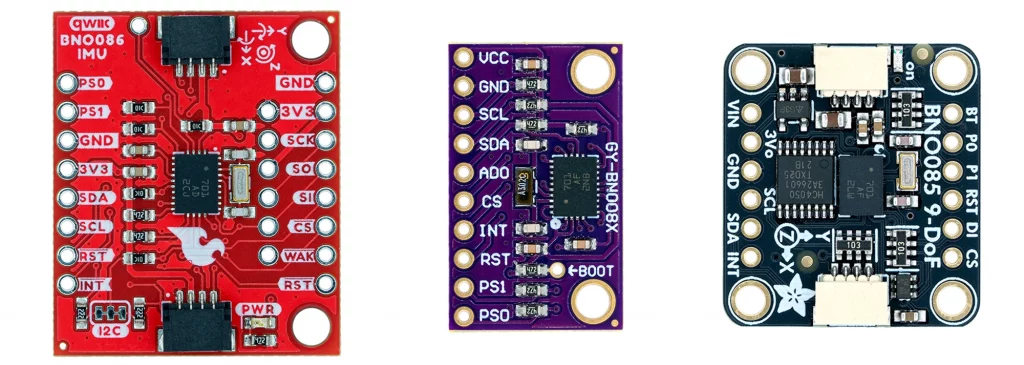
They all work fine, but differ in some respects. For example, the I²C address of the Sparkfun and the no-name module is preset to 0x4B (ADO = HIGH). The default setting for the Adafruit module is 0x4A (ADO = LOW). Both the Adafruit and the Sparkfun modules are equipped with the very practical QWIIC connector for I²C communication. All three modules have pull-up resistors for the I²C lines.
Only the Adafruit module can be operated with 5 volts. It has a voltage regulator and level shifters for the inputs and outputs.
Key electrical characteristics
- Power supply: 2.4 – 3.6 volts (Adafruit module: also 5V).
- Power consumption: The power consumption depends on various factors, such as the data rates (see data sheet, chapter 6.10).
- As a guide: I measured the following values with the Sparkfun sketch “Example_18_Sleep.ino” at 3.3 volts power supply and I²C communication:
- Sleep mode: approx. 0.2 mA.
- Awake mode: approx. 12.3 mA.
- As a guide: I measured the following values with the Sparkfun sketch “Example_18_Sleep.ino” at 3.3 volts power supply and I²C communication:
Communication
The BNO08x modules can handle I²C, SPI, UART and UART-RVC. UART-RVC is a UART variant that only requires a single data cable (RVC = Rotation Vector Channel). The disadvantage of this variant is that only a limited range of functions is available to you. You also need a separate library.
You select the communication protocol via the PS pins (Protocoll Selection):
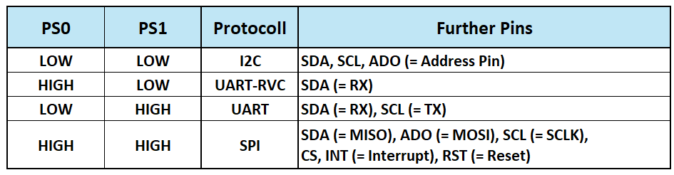
For all three modules shown above, PS0 and PS1 are connected to GND with pull-down resistors. You can set them permanently to HIGH via solder bridges on the back of the modules. Alternatively, you can use the pins.
Outputs (reports) of the BNO08x modules
The measurement data from the BNO08x modules is requested as so-called reports. You define what you want once and then receive the corresponding data continuously. In principle, it’s like a newspaper subscription. You know approximately when to expect the deliveries, but you only know the exact time when the delivery actually arrives.
The range of reports is impressive. They can be divided into three groups:
1. Motion reports
These reports contain raw or processed data from the individual sensors.
- Acceleration values:
- Calibrated acceleration data, including gravity (in m/s²)
- Linear acceleration: Acceleration data, excluding gravity (in m/s²)
- Acceleration due to gravity: pure gravity (in m/s²)
- Uncalibrated raw data of the A/D converter
- Angular velocity:
- Calibrated gyroscope data (in rad/s)
- Uncalibrated gyroscope data (in rad/s)
- Uncalibrated raw data of the AD/converter
- Magnetometer processing:
- Calibrated magnetic field (µTesla)
- Uncalibrated magnetic field (µTesla)
- Uncalibrated raw data of the A/D converter
2. Orientation reports
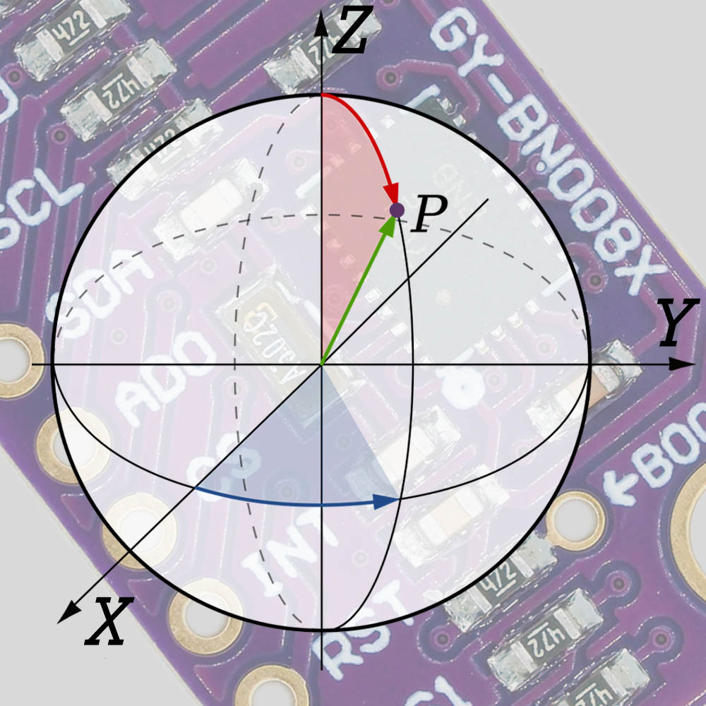
If the data from the sensors is combined (“sensor fusion”), the absolute orientation of the module in space or in relation to a reference point can be determined. The reports usually output the data as quaternions. Quaternions are a mathematical method for describing the spatial rotation of bodies. Further mathematical operations are required to obtain descriptive data from quaternions. The detour via quaternions is necessary because the use of angles (“Yaw”, “Pitch”, “Roll”) can lead to problems such as gimbal lock in certain borderline cases.
The selection of the orientation report is always a trade-off between precision and speed or latency. You can choose from:
- Geomagnetic Rotation Vector: Orientation referenced to magnetic north and gravity. Only the magnetometer and accelerometer are used, not the gyroscope.
- Game Rotation Vector: Based on the accelerometer and the gyroscope. As the magnetometer is not used, the yaw angle can drift over time. The advantage of this method is its low latency, which makes it particularly suitable for game and VR applications.
- AR/VR Stabilized Game Rotation Vector: Corrected variant (see data sheet, section 2.2.3)
- Rotation Vector: Uses accelerometer, gyroscope and magnetometer and therefore provides the most accurate absolute orientation.
- AR/VR Stabilized Rotation Vector: Corrected variant (see data sheet, section 2.2.5).
- Gyro rotation vector: Special variant of the rotation or game rotation vector. (see data sheet, section 2.2.6)
- Gyro Rotation Vector Prediction: Prediction of where the Gyro Protection Vector will move to next (see data sheet, section 2.2.7).
3. Classification reports
More complex movement patterns can be derived from the change in movement and orientation data over time. These are the so-called classification reports:
- Stability Detection and Classification:
- On table: Sensor lies absolutely still.
- Stable: Sensor is held steady in the hand.
- Motion: Sensor is moved.
- Tap Detector: Detects taps.
- Step Counter: Counts steps.
- Activity Classification: Still, walking, or running.
- Significant Motion Detector: Detects significant motion.
- Shake Detector: Detects shaking.
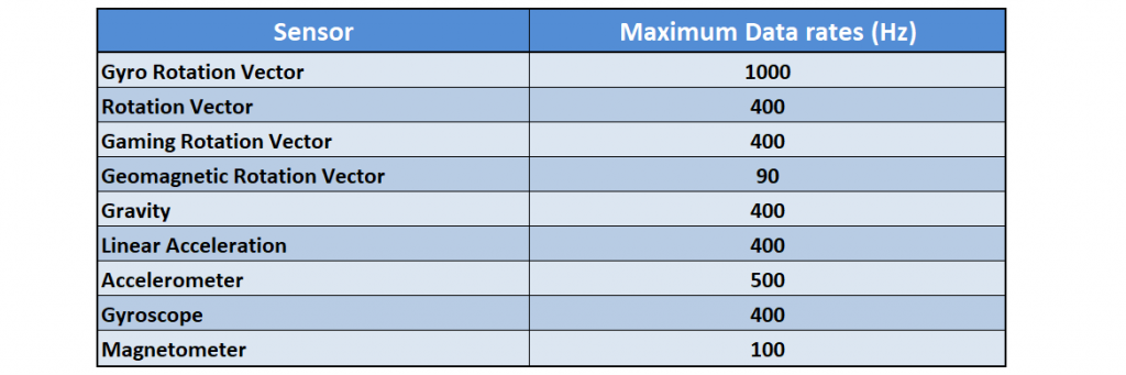
Report frequencies
The number of reports per second that the BNO08x modules can deliver depends on the speed of the communication protocol (i.e. I²C, SPI, UART) and the internal processing time. In addition, the maximum data rates of the underlying sensors must be considered, whereby not all sensors can deliver the maximum data rate at the same time.
As you will see, the time between reports can be configured (within reasonable limits). However, the actual report rate can be 0.9 to 2.1 times the desired value.
Calibration
The BNO08x modules can be calibrated dynamically, i.e. during operation:
- Accelerometer: Removal of the “zero-g offset”. At rest, only the force of gravity acts on the sensor. Any deviations from this are eliminated during calibration.
- Gyroscope: Removal of the “zero rate offset”. At rest, the gyroscope sensors should display an angular velocity of 0. All deviations from this are eliminated during calibration.
- Magnetometer: Elimination of interference with the magnetic field, e.g. from magnets, loudspeakers or ferromagnetic materials.
The better the calibration, the more accurate the measurement results. The accuracy of the values is classified on a scale from 0 (unreliable) to 3 (high reliability).
Libraries – Sparkfun and Adafruit
In this article, I will look at the libraries “SparkFun BNO08x Cortex Based IMU” and “Adafruit BNO08x“. Tutorials on the libraries and the respective modules can be found here on the Sparkfun website or here on the Adafruit website.
In principle, both libraries work well. However, they have their strengths and weaknesses. In favor of the Sparkfun library (in my opinion and based on the current versions of the libraries!):
- Contains many example sketches.
- Implementation of sleep mode.
- The calibration is more transparent (see example sketch no. 20).
- More stable I²C communication.
This speaks in favor of the Adafruit library:
- Implementation of UART (UART-RVC is implemented in a separate Adafruit library).
- Setting the report period is more flexible. For the Sparkfun library, the period is (currently) limited to a maximum of 65 milliseconds.
- The Adafruit library is closer to the SH-2 software and the SH-2 API.
Connecting the BNO08x modules to the microcontroller (I²C)
How you connect your module to the microcontroller depends on the module and the desired communication protocol. I will show everything here using the example of the no-name module, which is controlled via an ESP32 development board. I have chosen I²C as the protocol for the example sketches. In the appendix, you will find circuit diagrams and example sketches using SPI, UART, and UART-RVC. Moreover, I will also show you how to use 5-volt boards.
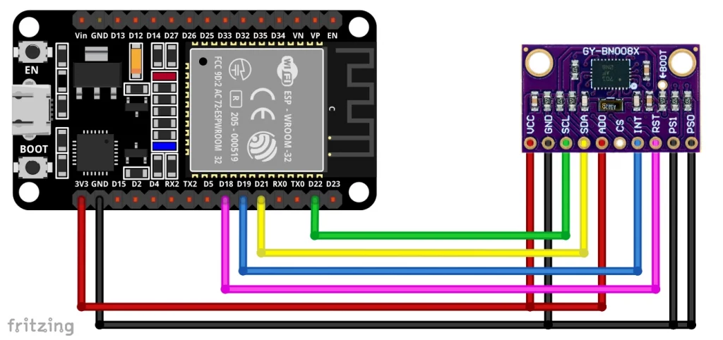
In this configuration, the connections to PS0, PS1, and ADO are redundant, as the no-name board has corresponding pull-up and pull-down resistors. If you use the Adafruit library, you do not need to connect INT and RST.
Instructions for wiring the Adafruit module can be found here, for wiring the Sparkfun module look here.
When using the Sparkfun library, you should connect INT and RST for all communication protocols.
I²C can cause problems with the BNO08x modules (see here). If this is the case for you, then it is best to switch to SPI. SPI is also ahead of the pack when it comes to speed.
Selected example sketches
Now we can finally turn to the practical side of things. I cannot go through all the report functions in this article. I will show you an example of a motion report, one for an orientation report and one for a classification report. Finally, let’s take a look at how to output several reports.
Motion example: Accelerometer values
Accelerometer values using the Sparkfun library
The Sparkfun library contains example sketches for almost all reports. We will take a look at the example sketch Example_02_Accelerometer.ino which I have modified regarding the reset and the interrupt pin.
/*
  Using the BNO08x IMU

  This example shows how to output accelerometer values.

  By: Nathan Seidle
  SparkFun Electronics
  Date: December 21st, 2017
  SparkFun code, firmware, and software is released under the MIT License.
  Please see LICENSE.md for further details.

  Originally written by Nathan Seidle @ SparkFun Electronics, December 28th, 2017

  Adjusted by Pete Lewis @ SparkFun Electronics, June 2023 to incorporate the
  CEVA Sensor Hub Driver, found here:
  https://github.com/ceva-dsp/sh2

  Also, utilizing code from the Adafruit BNO08x Arduino Library by Bryan Siepert
  for Adafruit Industries. Found here:
  https://github.com/adafruit/Adafruit_BNO08x

  Also, utilizing I2C and SPI read/write functions and code from the Adafruit
  BusIO library found here:
  https://github.com/adafruit/Adafruit_BusIO

  Hardware Connections: // changed for this blog post by Wolfgang Ewald
  ESP32 --> BNO08x
  19  --> INT
  18  --> RST

  BNO08x "mode" jumpers set for I2C (default):
  PSO: Open
  PS1: Open

  Serial.print it out at 115200 baud to serial monitor.

  Feel like supporting our work? Buy a board from SparkFun!
  https://www.sparkfun.com/products/22857
*/

#include <Wire.h>

#include "SparkFun_BNO08x_Arduino_Library.h" // CTRL+Click here to get the library: http://librarymanager/All#SparkFun_BNO08x
BNO08x myIMU;

// For the most reliable interaction with the SHTP bus, we need
// to use hardware reset control, and to monitor the H_INT pin.
// The H_INT pin will go low when its okay to talk on the SHTP bus.
// Note, these can be other GPIO if you like.
// Define as -1 to disable these features.
#define BNO08X_INT  19
//#define BNO08X_INT  -1
#define BNO08X_RST  18
//#define BNO08X_RST  -1

#define BNO08X_ADDR 0x4B  // SparkFun BNO08x Breakout (Qwiic) defaults to 0x4B
//#define BNO08X_ADDR 0x4A // Alternate address if ADR jumper is closed

void setup() {
  Serial.begin(115200);

  while(!Serial) delay(10); // Wait for Serial to become available.
  // Necessary for boards with native USB (like the SAMD51 Thing+).
  // For a final version of a project that does not need serial debug (or a USB cable plugged in),
  // Comment out this while loop, or it will prevent the remaining code from running.

  Serial.println();
  Serial.println("BNO08x Read Example");

  Wire.begin();

  //if (myIMU.begin() == false) {  // Setup without INT/RST control (Not Recommended)
  if (myIMU.begin(BNO08X_ADDR, Wire, BNO08X_INT, BNO08X_RST) == false) {
    Serial.println("BNO08x not detected at default I2C address. Check your jumpers and the hookup guide. Freezing...");
    while (1)
      ;
  }
  Serial.println("BNO08x found!");

  // Wire.setClock(400000); //Increase I2C data rate to 400kHz

  setReports();

  Serial.println("Reading events");
  delay(100);
}

// Here is where you define the sensor outputs you want to receive
void setReports(void) {
  Serial.println("Setting desired reports");
  if (myIMU.enableAccelerometer() == true) {
    Serial.println(F("Accelerometer enabled"));
    Serial.println(F("Output in form x, y, z, in m/s^2"));
  } else {
    Serial.println("Could not enable accelerometer");
  }
}

void loop() {
  delay(10);

  if (myIMU.wasReset()) {
    Serial.print("sensor was reset ");
    setReports();
  }

  // Has a new event come in on the Sensor Hub Bus?
  if (myIMU.getSensorEvent() == true) {

    // is it the correct sensor data we want?
    if (myIMU.getSensorEventID() == SENSOR_REPORTID_ACCELEROMETER) {

      float x = myIMU.getAccelX();
      float y = myIMU.getAccelY();
      float z = myIMU.getAccelZ();

      Serial.print(x, 2);
      Serial.print(F(","));
      Serial.print(y, 2);
      Serial.print(F(","));
      Serial.print(z, 2);

      Serial.println();
    }
  }
}
I won’t go into every single line of code because most of it should be self-explanatory. With begin(BNO08X_ADDR, Wire, BNO08X_INT, BNO08X_RST), youitialize your BNO08x object and pass the I²C address, the wire object, the interrupt pin, and the reset pin.
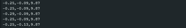
In setReports(), the accelerometer or accelerometer reports are activated via enableAccelerometer(). In loop(), getSensorEvent() queries whether there is an event. If so, getSensorEventID() determines the ID of the event. If this is the accelerometer report ID, the x, y, and z values are queried and output. The unit of the values is m/s². To convert them into g-values, divide them by 9.81.
If a reset of the BNO08x was necessary (wasReset() == true), the reports are automatically reset.
Here is the output I obtained:
Accelerometer values using the Adafruit library
The Adafruit library is equipped with fewer example sketches, but you can use the example sketch more_reports.ino as a basis and delete the parts that you don’t need. This is how I prepared this sketch.
// Basic demo for readings from Adafruit BNO08x
#include <Adafruit_BNO08x.h>

// For SPI mode, we need a CS pin
#define BNO08X_CS 10
#define BNO08X_INT 19

// For SPI mode, we also need a RESET
//#define BNO08X_RESET 5
// but not for I2C or UART
#define BNO08X_RESET -1

Adafruit_BNO08x  bno08x(BNO08X_RESET);
sh2_SensorValue_t sensorValue;

void setup(void) {
  Serial.begin(115200);
  while (!Serial) delay(10);     // will pause Zero, Leonardo, etc until serial console opens

  Serial.println("Adafruit BNO08x Accelerometer test!");

  // Try to initialize!
  if (!bno08x.begin_I2C(/* 0x4B */)) {
  //if (!bno08x.begin_UART(&Serial1)) {  // Requires a device with > 300 byte UART buffer!
  //if (!bno08x.begin_SPI(BNO08X_CS, BNO08X_INT)) {
    Serial.println("Failed to find BNO08x chip");
    while (1) { delay(10); }
  }
  Serial.println("BNO08x Found!");

  for (int n = 0; n < bno08x.prodIds.numEntries; n++) {
    Serial.print("Part ");
    Serial.print(bno08x.prodIds.entry[n].swPartNumber);
    Serial.print(": Version :");
    Serial.print(bno08x.prodIds.entry[n].swVersionMajor);
    Serial.print(".");
    Serial.print(bno08x.prodIds.entry[n].swVersionMinor);
    Serial.print(".");
    Serial.print(bno08x.prodIds.entry[n].swVersionPatch);
    Serial.print(" Build ");
    Serial.println(bno08x.prodIds.entry[n].swBuildNumber);
  }

  setReports();

  Serial.println("Reading events");
  delay(100);
}

// Here is where you define the sensor outputs you want to receive
void setReports(void) {
  Serial.println("Setting desired reports");
  if (! bno08x.enableReport(SH2_ACCELEROMETER)) {
    Serial.println("Could not enable accelerometerame vector");
  }
}


void loop() {
  delay(10);

  if (bno08x.wasReset()) {
    Serial.print("sensor was reset ");
    setReports();
  }

  if (! bno08x.getSensorEvent(&sensorValue)) {
    return;
  }

  switch (sensorValue.sensorId) {

    case SH2_ACCELEROMETER:
      Serial.print("Accelerometer - x: ");
      Serial.print(sensorValue.un.accelerometer.x);
      Serial.print(" y: ");
      Serial.print(sensorValue.un.accelerometer.y);
      Serial.print(" z: ");
      Serial.println(sensorValue.un.accelerometer.z);
      break;
  }
}
First, you create a BNO08x object as usual. In addition, you create the structure sensorValue of type sh2_SensorValue_t, which you later pass to the function getSensorEvent() in loop() as a reference. sensorValue is a form, so to speak, in which the values are entered. It is worth taking a look at the file sh2_SensorValue.h to understand the composition of this structure. sh2_SensorValue.h is also used by the Sparkfun library – but there it is somewhat more hidden behind the scenes.
You initialize the module with begin_I2C(). You can optionally pass the I²C address. The large for-construct in setup() tells you details about the module. You can also omit this if you like.
In setupReports(), use enableReport(SH2_REPORTNAME) to activate the report of your choice. You can find the report names or the corresponding IDs either in the example sketch moreReports.ino, or you can look in the file sh2.h, in which the names are defined in the enum sh2_SensorId_e.
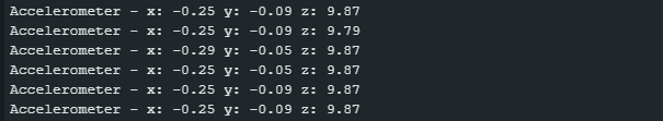
Personally, I like how closely the Adafruit library follows the SH-2 API. Expressions like sensorValue.un.accelerometer.z may seem a bit cumbersome compared to a slim myIMU.getAccelZ(); at first glance, but I like the logical structure behind it.
Example Orientation: Rotation vector (Euler angles)
Rotation vector using the Sparkfun lib
The following sketch outputs the orientation of the BNO08x in three-dimensional space as yaw, pitch and roll angles. Yaw, pitch and roll are known as Euler angles.
The Rotation Vector Report actually returns the orientation as a quaternion; the Sparkfun library converts the quaternions into Euler angles in the background, which are then converted from rad to degrees. Apart from that, the sketch does not actually contain anything new.
/*
  Using the BNO08x IMU

  Example : Euler Angles
  By: Paul Clark
  Date: April 28th, 2020

  This example shows how to output the Euler angles: roll, pitch and yaw.
  The yaw (compass heading) is tilt-compensated, which is nice.
  https://en.wikipedia.org/wiki/Conversion_between_quaternions_and_Euler_angles
  https://github.com/sparkfun/SparkFun_MPU-9250-DMP_Arduino_Library/issues/5#issuecomment-306509440

  By: Nathan Seidle
  SparkFun Electronics
  Date: December 21st, 2017
  SparkFun code, firmware, and software is released under the MIT License.
  Please see LICENSE.md for further details.

  Originally written by Nathan Seidle @ SparkFun Electronics, December 28th, 2017

  Adjusted by Pete Lewis @ SparkFun Electronics, June 2023 to incorporate the
  CEVA Sensor Hub Driver, found here:
  https://github.com/ceva-dsp/sh2

  Also, utilizing code from the Adafruit BNO08x Arduino Library by Bryan Siepert
  for Adafruit Industries. Found here:
  https://github.com/adafruit/Adafruit_BNO08x

  Also, utilizing I2C and SPI read/write functions and code from the Adafruit
  BusIO library found here:
  https://github.com/adafruit/Adafruit_BusIO

  Hardware Connections:
  IoT RedBoard --> BNO08x
  QWIIC --> QWIIC
  A4  --> INT
  A5  --> RST

  BNO08x "mode" jumpers set for I2C (default):
  PSO: OPEN
  PS1: OPEN

  Serial.print it out at 115200 baud to serial monitor.

  Feel like supporting our work? Buy a board from SparkFun!
  https://www.sparkfun.com/products/22857
*/

#include <Wire.h>

#include "SparkFun_BNO08x_Arduino_Library.h"  // CTRL+Click here to get the library: http://librarymanager/All#SparkFun_BNO08x
BNO08x myIMU;

// For the most reliable interaction with the SHTP bus, we need
// to use hardware reset control, and to monitor the H_INT pin.
// The H_INT pin will go low when its okay to talk on the SHTP bus.
// Note, these can be other GPIO if you like.
// Define as -1 to disable these features.
#define BNO08X_INT  19
//#define BNO08X_INT  -1
#define BNO08X_RST  18
//#define BNO08X_RST  -1

#define BNO08X_ADDR 0x4B  // SparkFun BNO08x Breakout (Qwiic) defaults to 0x4B
//#define BNO08X_ADDR 0x4A // Alternate address if ADR jumper is closed

void setup() {
  Serial.begin(115200);

  while(!Serial) delay(10); // Wait for Serial to become available.
  // Necessary for boards with native USB (like the SAMD51 Thing+).
  // For a final version of a project that does not need serial debug (or a USB cable plugged in),
  // Comment out this while loop, or it will prevent the remaining code from running.

  Serial.println();
  Serial.println("BNO08x Read Example");

  Wire.begin();

  //if (myIMU.begin() == false) {  // Setup without INT/RST control (Not Recommended)
  if (myIMU.begin(BNO08X_ADDR, Wire, BNO08X_INT, BNO08X_RST) == false) {
    Serial.println("BNO08x not detected at default I2C address. Check your jumpers and the hookup guide. Freezing...");
    while (1)
      ;
  }
  Serial.println("BNO08x found!");

  // Wire.setClock(400000); //Increase I2C data rate to 400kHz

  setReports();

  Serial.println("Reading events");
  delay(100);
}

// Here is where you define the sensor outputs you want to receive
void setReports(void) {
  Serial.println("Setting desired reports");
  if (myIMU.enableRotationVector() == true) {
    Serial.println(F("Rotation vector enabled"));
    Serial.println(F("Output in form roll, pitch, yaw"));
  } else {
    Serial.println("Could not enable rotation vector");
  }
}

void loop() {
  delay(10);

  if (myIMU.wasReset()) {
    Serial.print("sensor was reset ");
    setReports();
  }

  // Has a new event come in on the Sensor Hub Bus?
  if (myIMU.getSensorEvent() == true) {

    // is it the correct sensor data we want?
    if (myIMU.getSensorEventID() == SENSOR_REPORTID_ROTATION_VECTOR) {

    float roll = (myIMU.getRoll()) * 180.0 / PI; // Convert roll to degrees
    float pitch = (myIMU.getPitch()) * 180.0 / PI; // Convert pitch to degrees
    float yaw = (myIMU.getYaw()) * 180.0 / PI; // Convert yaw / heading to degrees

    Serial.print(roll, 1);
    Serial.print(F(","));
    Serial.print(pitch, 1);
    Serial.print(F(","));
    Serial.print(yaw, 1);

    Serial.println();
    }
  }
}
The function enableRotationVector() activates the rotation vector report, which has the ID SENSOR_REPORTID_ROTATION_VECTOR. If a corresponding report is available, the angles are queried with getRoll(), getPitch() and getYaw() and converted from rad to degrees.
Alternative rotation vectors
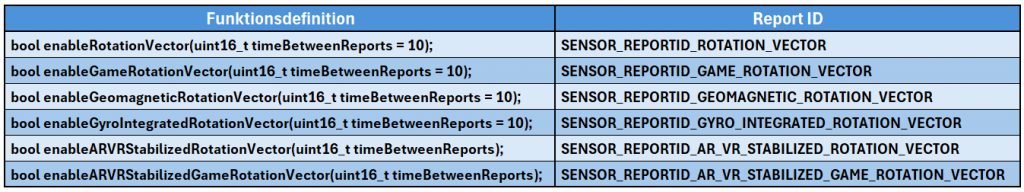
Instead of the rotation vector, you could also have selected a different rotation vector as the basis for the Euler angles. For example: If you wanted to use the “AR/VR Stabilized Game Rotation Vector”, you would have to replace the following:
- Line 99:
enableRotationVector()throughenableARVRStabilizedGameRotationVector(timeBetweenReports). The report period (timeBetweenReports) must be transferred in milliseconds. - Line 119:
SENSOR_REPORTID_ROTATION_VECTORthroughSENSOR_REPORTID_AR_VR_STABILIZED_GAME_ROTATION_VECTOR.
The Sparkfun library could be a little better documented here. I have therefore summarized the rotation vector report IDs and the associated enable functions in a table (see below). It is not clear to me why the time between the reports is not specified for some enable functions.
Rotation vector using the Adafruit lib
The Adafruit library is also equipped with an example sketch for the output of Euler angles. In contrast to the Sparkfun library, the conversion of the quaternions does not take place in the background but is part of the sketch.
The sketch got stuck after a while when I used I²C and an ESP32 development board. Adafruit points out that there may be problems with I²C in conjunction with some boards (see here). Mit SPI gab es bei mir keine Probleme.
#include <Arduino.h>
// This demo explores two reports (SH2_ARVR_STABILIZED_RV and SH2_GYRO_INTEGRATED_RV) both can be used to give
// quartenion and euler (yaw, pitch roll) angles.  Toggle the FAST_MODE define to see other report.
// Note sensorValue.status gives calibration accuracy (which improves over time)
#include <Adafruit_BNO08x.h>

// For SPI mode, we need a CS pin
#define BNO08X_CS 10
#define BNO08X_INT 19


// #define FAST_MODE

// For SPI mode, we also need a RESET
//#define BNO08X_RESET 5
// but not for I2C or UART
#define BNO08X_RESET -1

struct euler_t {
  float yaw;
  float pitch;
  float roll;
} ypr;

Adafruit_BNO08x  bno08x(BNO08X_RESET);
sh2_SensorValue_t sensorValue;

#ifdef FAST_MODE
  // Top frequency is reported to be 1000Hz (but freq is somewhat variable)
  sh2_SensorId_t reportType = SH2_GYRO_INTEGRATED_RV;
  long reportIntervalUs = 2000;
#else
  // Top frequency is about 250Hz but this report is more accurate
  sh2_SensorId_t reportType = SH2_ARVR_STABILIZED_RV;
  long reportIntervalUs = 5000;
#endif
void setReports(sh2_SensorId_t reportType, long report_interval) {
  Serial.println("Setting desired reports");
  if (! bno08x.enableReport(reportType, report_interval)) {
    Serial.println("Could not enable stabilized remote vector");
  }
}

void setup(void) {

  Serial.begin(115200);
  while (!Serial) delay(10);     // will pause Zero, Leonardo, etc until serial console opens

  Serial.println("Adafruit BNO08x test!");

  // Try to initialize!
  if (!bno08x.begin_I2C(/* 0x4B */)) {  // ADO = HIGH => I2C Address = 0x4B
  //if (!bno08x.begin_UART(&Serial1)) {  // Requires a device with > 300 byte UART buffer!
  //if (!bno08x.begin_SPI(BNO08X_CS, BNO08X_INT)) {
    Serial.println("Failed to find BNO08x chip");
    while (1) { delay(10); }
  }
  Serial.println("BNO08x Found!");


  setReports(reportType, reportIntervalUs);

  Serial.println("Reading events");
  delay(100);
}

void quaternionToEuler(float qr, float qi, float qj, float qk, euler_t* ypr, bool degrees = false) {

    float sqr = sq(qr);
    float sqi = sq(qi);
    float sqj = sq(qj);
    float sqk = sq(qk);

    ypr->yaw = atan2(2.0 * (qi * qj + qk * qr), (sqi - sqj - sqk + sqr));
    ypr->pitch = asin(-2.0 * (qi * qk - qj * qr) / (sqi + sqj + sqk + sqr));
    ypr->roll = atan2(2.0 * (qj * qk + qi * qr), (-sqi - sqj + sqk + sqr));

    if (degrees) {
      ypr->yaw *= RAD_TO_DEG;
      ypr->pitch *= RAD_TO_DEG;
      ypr->roll *= RAD_TO_DEG;
    }
}

void quaternionToEulerRV(sh2_RotationVectorWAcc_t* rotational_vector, euler_t* ypr, bool degrees = false) {
    quaternionToEuler(rotational_vector->real, rotational_vector->i, rotational_vector->j, rotational_vector->k, ypr, degrees);
}

void quaternionToEulerGI(sh2_GyroIntegratedRV_t* rotational_vector, euler_t* ypr, bool degrees = false) {
    quaternionToEuler(rotational_vector->real, rotational_vector->i, rotational_vector->j, rotational_vector->k, ypr, degrees);
}

void loop() {

  if (bno08x.wasReset()) {
    Serial.print("sensor was reset ");
    setReports(reportType, reportIntervalUs);
  }

  if (bno08x.getSensorEvent(&sensorValue)) {
    // in this demo only one report type will be received depending on FAST_MODE define (above)
    switch (sensorValue.sensorId) {
      case SH2_ARVR_STABILIZED_RV:
        quaternionToEulerRV(&sensorValue.un.arvrStabilizedRV, &ypr, true);
      case SH2_GYRO_INTEGRATED_RV:
        // faster (more noise?)
        quaternionToEulerGI(&sensorValue.un.gyroIntegratedRV, &ypr, true);
        break;
    }
    static long last = 0;
    long now = micros();
    Serial.print(now - last);             Serial.print("\t");
    last = now;
    Serial.print(sensorValue.status);     Serial.print("\t");  // This is accuracy in the range of 0 to 3
    Serial.print(ypr.yaw);                Serial.print("\t");
    Serial.print(ypr.pitch);              Serial.print("\t");
    Serial.println(ypr.roll);
  }

}
As you can see, in this example you can switch between the AR/VR Stabilized Rotation Vector and the Gyro Rotation Vector (which is faster but less precise) as a basis using by (un-)commenting #define FAST_MODE.
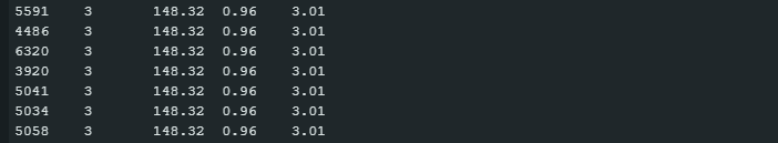
In addition to the Euler angles, the sketch shows the time between the report outputs and the reliability of the values (accuracy). The following output example indicates that the time between reports can deviate quite considerably from the configured (5000 µs):
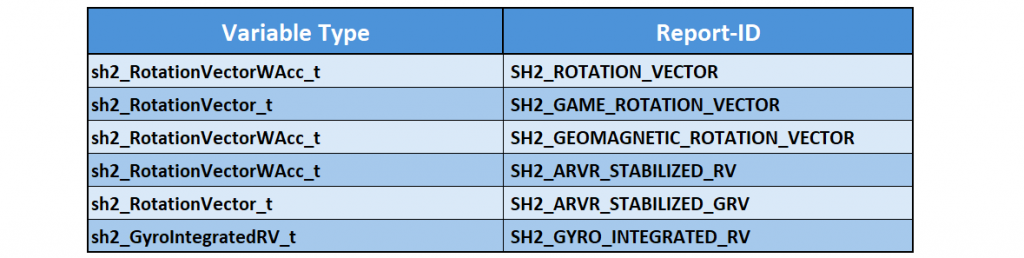
It is also possible to use other Rotation Vector reports. However, you need to know the names of the report IDs and the associated variable types. You can find them in sh2_SensorValue.h or in this table:
Example Classification – Step Counter
As an example of a classification report, let’s take a look at the step counter.
Step Counter using the Sparkfun lib
Apart from the fact that we are activating the step counter report here, there is nothing fundamentally new in this sketch.
/*
  Using the BNO08x IMU

  This example shows the step count. Tap the IC a few times to emulate a step.

  By: Nathan Seidle
  SparkFun Electronics
  Date: December 21st, 2017
  SparkFun code, firmware, and software is released under the MIT License.
  Please see LICENSE.md for further details.

  Originally written by Nathan Seidle @ SparkFun Electronics, December 28th, 2017

  Adjusted by Pete Lewis @ SparkFun Electronics, June 2023 to incorporate the
  CEVA Sensor Hub Driver, found here:
  https://github.com/ceva-dsp/sh2

  Also, utilizing code from the Adafruit BNO08x Arduino Library by Bryan Siepert
  for Adafruit Industries. Found here:
  https://github.com/adafruit/Adafruit_BNO08x

  Also, utilizing I2C and SPI read/write functions and code from the Adafruit
  BusIO library found here:
  https://github.com/adafruit/Adafruit_BusIO

  Hardware Connections:
  IoT RedBoard --> BNO08x
  QWIIC --> QWIIC
  A4  --> INT
  A5  --> RST

  BNO08x "mode" jumpers set for I2C (default):
  PSO: OPEN
  PS1: OPEN

  Serial.print it out at 115200 baud to serial monitor.

  Feel like supporting our work? Buy a board from SparkFun!
  https://www.sparkfun.com/products/22857
*/

#include <Wire.h>

#include "SparkFun_BNO08x_Arduino_Library.h" // CTRL+Click here to get the library: http://librarymanager/All#SparkFun_BNO08x
BNO08x myIMU;

// For the most reliable interaction with the SHTP bus, we need
// to use hardware reset control, and to monitor the H_INT pin.
// The H_INT pin will go low when its okay to talk on the SHTP bus.
// Note, these can be other GPIO if you like.
// Define as -1 to disable these features.
#define BNO08X_INT  19
//#define BNO08X_INT  -1
#define BNO08X_RST  18
//#define BNO08X_RST  -1

#define BNO08X_ADDR 0x4B  // SparkFun BNO08x Breakout (Qwiic) defaults to 0x4B
//#define BNO08X_ADDR 0x4A // Alternate address if ADR jumper is closed

void setup() {
  Serial.begin(115200);

  while(!Serial) delay(10); // Wait for Serial to become available.
  // Necessary for boards with native USB (like the SAMD51 Thing+).
  // For a final version of a project that does not need serial debug (or a USB cable plugged in),
  // Comment out this while loop, or it will prevent the remaining code from running.

  Serial.println();
  Serial.println("BNO08x Read Example");

  Wire.begin();

  //if (myIMU.begin() == false) {  // Setup without INT/RST control (Not Recommended)
  if (myIMU.begin(BNO08X_ADDR, Wire, BNO08X_INT, BNO08X_RST) == false) {
    Serial.println("BNO08x not detected at default I2C address. Check your jumpers and the hookup guide. Freezing...");
    while (1)
      ;
  }
  Serial.println("BNO08x found!");

  // Wire.setClock(400000); //Increase I2C data rate to 400kHz

  setReports();

  Serial.println("Reading events");
  delay(100);
}

// Here is where you define the sensor outputs you want to receive
void setReports(void) {
  Serial.println("Setting desired reports");
  if (myIMU.enableStepCounter(65) == true) { //Send data update every 65 ms (maximum)
    Serial.println(F("Step Counter enabled"));
    Serial.println(F("Step count since sketch started:"));
  } else {
    Serial.println("Could not step counter");
  }
}

void loop() {
  delay(500); // step counter needs a little longer of delay (200ms or more)

  if (myIMU.wasReset()) {
    Serial.print("sensor was reset ");
    setReports();
  }

  // Has a new event come in on the Sensor Hub Bus?
  if (myIMU.getSensorEvent() == true) {

    // is it the correct sensor data we want?
    if (myIMU.getSensorEventID() == SENSOR_REPORTID_STEP_COUNTER) {

      unsigned int steps = myIMU.getStepCount();

      Serial.print(steps);

      Serial.println();
    }
  }
}
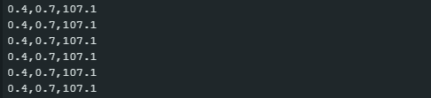
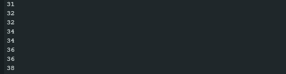
Here is an excerpt from the output of the sketch. To test the function, I took a few steps while standing in front of my desk with the breadboard in my hand (which probably looked pretty stupid). It works really well.
Step counter using the Adafruit lib
The Adafruit sketch for the step counter is also not very surprising. Only one aspect is new, namely the latency in microseconds with sensorValue.un.stepCounter.latency. The latency is the delay between the movement and the triggering of the event.
// Basic demo for readings from Adafruit BNO08x
#include <Adafruit_BNO08x.h>

// For SPI mode, we need a CS pin
#define BNO08X_CS 10
#define BNO08X_INT 19

// For SPI mode, we also need a RESET
//#define BNO08X_RESET 5
// but not for I2C or UART
#define BNO08X_RESET -1

Adafruit_BNO08x bno08x(BNO08X_RESET);
sh2_SensorValue_t sensorValue;

void setup(void) {
  Serial.begin(115200);
  while (!Serial)
    delay(10); // will pause Zero, Leonardo, etc until serial console opens

  Serial.println("Adafruit BNO08x test!");

  // Try to initialize!
  if (!bno08x.begin_I2C()) {
    // if (!bno08x.begin_UART(&Serial1)) {  // Requires a device with > 300 byte
    // UART buffer! if (!bno08x.begin_SPI(BNO08X_CS, BNO08X_INT)) {
    Serial.println("Failed to find BNO08x chip");
    while (1) {
      delay(10);
    }
  }
  Serial.println("BNO08x Found!");

  setReports();

  Serial.println("Reading Step Counter events");
  delay(100);
}

// Here is where you define the sensor outputs you want to receive
void setReports(void) {
  Serial.println("Setting desired reports");
  if (!bno08x.enableReport(SH2_STEP_COUNTER)) {
    Serial.println("Could not enable step counter");
 }
}

void loop() {
  delay(10);

  if (bno08x.wasReset()) {
    Serial.print("sensor was reset ");
    setReports();
  }

  if (!bno08x.getSensorEvent(&sensorValue)) {
    return;
  }

  switch (sensorValue.sensorId) {

  case SH2_STEP_COUNTER:
    Serial.print("Step Counter - steps: ");
    Serial.print(sensorValue.un.stepCounter.steps);
    Serial.print(" latency: ");
    Serial.println(sensorValue.un.stepCounter.latency);
    break;
  }
}
Here is the output on my serial monitor:
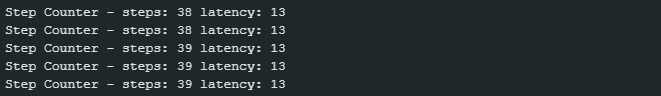
The latency values are extremely low while walking. If you start walking again after a pause, you will see that the latency for the first step is considerably higher.
Combining reports
So far we have only activated one report at a time. However, you can also activate several reports in parallel.
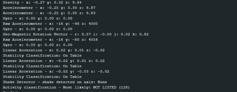
“Unordered” output using the example of Adafruit
I will start with the Adafruit library, as there is a sample sketch for it (more_reports.ino). In the screenshot below, you can see that the reports are displayed in a rather disorderly manner. For applications that just need to respond to certain conditions, that’s fine.
Step Counter and Stability Classification with Sparkfun
Using the step counter and activity classification, let’s take a look at how you can combine and time two reports.
The time between the reports can be set in the Sparkfun library with enablexxxx(timeBetweenReports). Here xxxx is the respective report, and timeBetweenReports is the period in milliseconds. Unfortunately, the period can (currently) only be extended to a maximum of 65 milliseconds. The default setting is 10 milliseconds.
My aim was to generate an output of the two reports approximately every second. This is beyond 65 milliseconds, and therefore the following sketch controls the output frequency of the step counter via millis(). The stability classification is only output if the steps have been output beforehand.
#include <Wire.h>
#include "SparkFun_BNO08x_Arduino_Library.h" // CTRL+Click here to get the library: http://librarymanager/All#SparkFun_BNO08x

BNO08x myIMU;

#define BNO08X_INT  19
//#define BNO08X_INT  -1
#define BNO08X_RST  18
//#define BNO08X_RST  -1

#define BNO08X_ADDR 0x4B  // SparkFun BNO08x Breakout (Qwiic) defaults to 0x4B
//#define BNO08X_ADDR 0x4A // Alternate address if ADR jumper is closed

#define OUTPUT_PERIOD_MS 1000 // One output per second

void setup() {
  Serial.begin(115200);

  while(!Serial) delay(10);

  Serial.println();
  Serial.println("BNO08x Read Example");

  Wire.begin();

  //if (myIMU.begin() == false) {  // Setup without INT/RST control (Not Recommended)
  if (myIMU.begin(BNO08X_ADDR, Wire, BNO08X_INT, BNO08X_RST) == false) {
    Serial.println("BNO08x not detected at default I2C address. Check your jumpers and the hookup guide. Freezing...");
    while (1)
      ;
  }
  Serial.println("BNO08x found!");

  // Wire.setClock(400000); //Increase I2C data rate to 400kHz

  setReports();

  Serial.println("Reading events");
  delay(100);
}

// Here is where you define the sensor outputs you want to receive
void setReports(void) {
  Serial.println("Setting desired reports");

  if (myIMU.enableStepCounter(65) == true) { //Send data update every 65 (
    Serial.println(F("Step Counter enabled"));
    Serial.println(F("Step count since sketch started:"));
  } else {
    Serial.println("Could not step counter");
  }

  if (myIMU.enableStabilityClassifier(65) == true) {
    Serial.println(F("Stability Classifier enabled"));
  } else {
    Serial.println("Could not enable Stability Classifier");
  }
}

void loop() {
  static unsigned long lastUpdateStepCounter = 0;
  static bool lastUpdateWasStepCounter = false;

  if (myIMU.wasReset()) {
    Serial.print("sensor was reset ");
    setReports();
  }

  if (myIMU.getSensorEvent() == true) {

    // is it the correct sensor data we want?
    if (myIMU.getSensorEventID() == SENSOR_REPORTID_STEP_COUNTER) {
      if(millis() - lastUpdateStepCounter > OUTPUT_PERIOD_MS){
        unsigned int steps = myIMU.getStepCount();

        Serial.print("Steps: ");
        Serial.println(steps);
        lastUpdateWasStepCounter = true;
        lastUpdateStepCounter = millis();
      }
    }

    if (myIMU.getSensorEventID() == SENSOR_REPORTID_STABILITY_CLASSIFIER) {
      if(lastUpdateWasStepCounter){
        byte classification = myIMU.getStabilityClassifier();

        if(classification == STABILITY_CLASSIFIER_UNKNOWN) Serial.print(F("Unknown classification"));
        else if(classification == STABILITY_CLASSIFIER_ON_TABLE) Serial.print(F("On table"));
        else if(classification == STABILITY_CLASSIFIER_STATIONARY) Serial.print(F("Stationary"));
        else if(classification == STABILITY_CLASSIFIER_STABLE) Serial.print(F("Stable"));
        else if(classification == STABILITY_CLASSIFIER_MOTION) Serial.print(F("Motion"));
        else if(classification == STABILITY_CLASSIFIER_RESERVED) Serial.print(F("[Reserved]"));

        Serial.println();
        lastUpdateWasStepCounter = false;
      }
    }
  }
}
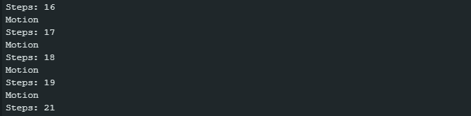
Here is a screenshot of the serial monitor:
Step Counter and Stability Classification with Adafruit
With the Adafruit library, it is easier to synchronize the outputs, as there is no restriction on the time between the reports (except that it is a uint32_t value). You pass this period to the function enableReport() as the second parameter in microseconds.
// Basic demo for readings from Adafruit BNO08x
#include <Adafruit_BNO08x.h>

// For SPI mode, we need a CS pin
#define BNO08X_CS 10
#define BNO08X_INT 19

// For SPI mode, we also need a RESET
//#define BNO08X_RESET 5
// but not for I2C or UART
#define BNO08X_RESET -1

Adafruit_BNO08x bno08x(BNO08X_RESET);
sh2_SensorValue_t sensorValue;

void setup(void) {
  Serial.begin(115200);
  while (!Serial)
    delay(10); // will pause Zero, Leonardo, etc. until serial console opens

  Serial.println("Adafruit BNO08x test!");

  // Try to initialize!
  if (!bno08x.begin_I2C()) {
    // if (!bno08x.begin_UART(&Serial1)) {  // Requires a device with > 300 byte
    // UART buffer! if (!bno08x.begin_SPI(BNO08X_CS, BNO08X_INT)) {
    Serial.println("Failed to find BNO08x chip");
    while (1) {
      delay(10);
    }
  }
  Serial.println("BNO08x Found!");

  setReports();

  Serial.println("Reading events");
  delay(100);
}

// Here is where you define the sensor outputs you want to receive
void setReports(void) {
  Serial.println("Setting desired reports");
  if (!bno08x.enableReport(SH2_STEP_COUNTER, 2000000)) { // period: 2s
    Serial.println("Could not enable step counter");
  }
  if (!bno08x.enableReport(SH2_STABILITY_CLASSIFIER, 2000000)) {  //period: 2s
    Serial.println("Could not enable stability classifier");
  }
}

void loop() {
  delay(10);
  if (bno08x.wasReset()) {
    Serial.print("sensor was reset ");
    setReports();
  }

  if (!bno08x.getSensorEvent(&sensorValue)) {
    return;
  }

  switch (sensorValue.sensorId) {

    case SH2_STEP_COUNTER:
      Serial.print("Step Counter - steps: ");
      Serial.print(sensorValue.un.stepCounter.steps);
      Serial.print(" latency: ");
      Serial.println(sensorValue.un.stepCounter.latency);
      break;

    case SH2_STABILITY_CLASSIFIER: {
      Serial.print("Stability Classification: ");
      sh2_StabilityClassifier_t stability = sensorValue.un.stabilityClassifier;
      switch (stability.classification) {
      case STABILITY_CLASSIFIER_UNKNOWN:
        Serial.println("Unknown");
        break;
      case STABILITY_CLASSIFIER_ON_TABLE:
        Serial.println("On Table");
        break;
      case STABILITY_CLASSIFIER_STATIONARY:
        Serial.println("Stationary");
        break;
      case STABILITY_CLASSIFIER_STABLE:
        Serial.println("Stable");
        break;
      case STABILITY_CLASSIFIER_MOTION:
        Serial.println("In Motion");
        break;
      }
      break;
    }
  }
}
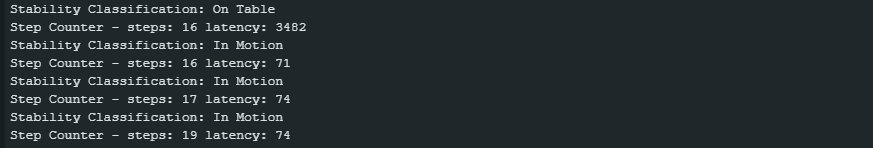
Here is the corresponding output:
Appendix – SPI, UART, UART-RVC, 5-volt boards
In the appendix, you will find circuits and sketches for alternative communication protocols and an example of the wiring for a 5-volt-based board.
SPI control of the BNO08x modules
Here is an example of connecting the no-name BNO08x module to an ESP32 development board via SPI:
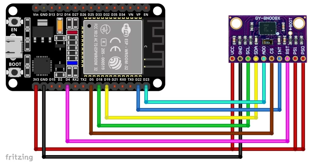
If you want to save cables, then pull up PS0 and PS1 by connecting the solder pads on the back of the module. If you only use one SPI device on the SPI interface, you could also pull CS permanently to GND.
SPI with Sparkfun
This is what the accelerometer sketch for the SPI connection looks like:
#include "SparkFun_BNO08x_Arduino_Library.h"
BNO08x myIMU;

#define BNO08X_CS   5
#define BNO08X_INT  22
#define BNO08X_RST  4

void setup() {
  Serial.begin(115200);

  while(!Serial) delay(10); // Wait for Serial to become available.

  Serial.println();
  Serial.println("BNO08x Read Example");

 if (myIMU.beginSPI(BNO08X_CS, BNO08X_INT, BNO08X_RST) == false) {
    Serial.println("BNO08x not detected. Check your jumpers and the hookup guide. Freezing...");
    while (1)
      ;
  }
  Serial.println("BNO08x found!");

  setReports();

  Serial.println("Reading events");
  delay(100);
}

// Here is where you define the sensor outputs you want to receive
void setReports(void) {
  Serial.println("Setting desired reports");
  if (myIMU.enableAccelerometer() == true) {
    Serial.println(F("Accelerometer enabled"));
    Serial.println(F("Output in form x, y, z, in m/s^2"));
  } else {
    Serial.println("Could not enable accelerometer");
  }
  delay(100); // important for SPI!

}

void loop() {
  delay(10);

  if (myIMU.wasReset()) {
    Serial.print("sensor was reset ");
    setReports();
  }

  // Has a new event come in on the Sensor Hub Bus?
  if (myIMU.getSensorEvent() == true) {

    // is it the correct sensor data we want?
    if (myIMU.getSensorEventID() == SENSOR_REPORTID_ACCELEROMETER) {

      float x = myIMU.getAccelX();
      float y = myIMU.getAccelY();
      float z = myIMU.getAccelZ();

      Serial.print(x, 2);
      Serial.print(F(","));
      Serial.print(y, 2);
      Serial.print(F(","));
      Serial.print(z, 2);

      Serial.println();
    }
  }
}
SPI with Adafruit
Here is the Adafruit SPI version:
#include <Adafruit_BNO08x.h>

#define BNO08X_CS 5
#define BNO08X_INT 22
#define BNO08X_RESET 4

Adafruit_BNO08x  bno08x(BNO08X_RESET);
sh2_SensorValue_t sensorValue;

void setup(void) {
  Serial.begin(115200);
  while (!Serial) delay(10);     // will pause Zero, Leonardo, etc until serial console opens

  Serial.println("Adafruit BNO08x Accelerometer test!");

  // Try to initialize!
  if (!bno08x.begin_SPI(BNO08X_CS, BNO08X_INT)) {
    Serial.println("Failed to find BNO08x chip");
    while (1) { delay(10); }
  }
  Serial.println("BNO08x Found!");

  setReports();

  Serial.println("Reading events");
  delay(100);
}

// Here is where you define the sensor outputs you want to receive
void setReports(void) {
  Serial.println("Setting desired reports");
  if (! bno08x.enableReport(SH2_ACCELEROMETER)) {
    Serial.println("Could not enable accelerometerame vector");
  }
}


void loop() {
  delay(10);

  if (bno08x.wasReset()) {
    Serial.print("sensor was reset ");
    setReports();
  }

  if (! bno08x.getSensorEvent(&sensorValue)) {
    return;
  }

  switch (sensorValue.sensorId) {

    case SH2_ACCELEROMETER:
      Serial.print("Accelerometer - x: ");
      Serial.print(sensorValue.un.accelerometer.x);
      Serial.print(" y: ");
      Serial.print(sensorValue.un.accelerometer.y);
      Serial.print(" z: ");
      Serial.println(sensorValue.un.accelerometer.z);
      break;
  }
}
UART control (Adafruit only)
The UART control is only implemented in the Adafruit library. It is advisable not to use the same serial interface as for the connection to the serial monitor. In my example circuit and the associated sketch, I use pins 18 and 19 as RX2 and TX2 respectively.
If you are using a board like the one shown below: I could also have used the pins labeled RX2 and TX2. However, they are assigned to GPIOs 16 and 17. In the ESP32 board package, however, RX2 and TX2 are assigned to pins 4 and 25. Because of this confusion, I decided to use other pins.
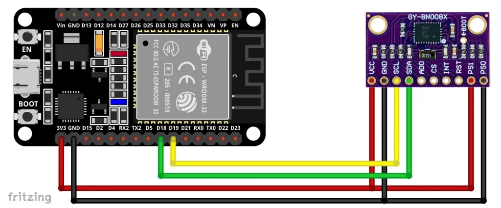
Here is the example sketch:
#include <Adafruit_BNO08x.h>

#define BNO08X_RESET -1
#define RX2 18
#define TX2 19

Adafruit_BNO08x  bno08x(BNO08X_RESET);
sh2_SensorValue_t sensorValue;

void setup(void) {
  Serial.begin(115200);
  Serial2.begin(115200, SERIAL_8N1, RX2, TX2);
  while (!Serial) delay(10);     // will pause Zero, Leonardo, etc until serial console opens
  while (!Serial2) delay(10);

  Serial.println("Adafruit BNO08x Accelerometer test!");

  // Try to initialize!
  if (!bno08x.begin_UART(&Serial2)) {  // Requires a device with > 300 byte UART buffer!
    Serial.println("Failed to find BNO08x chip");
    while (1) { delay(10); }
  }
  Serial.println("BNO08x Found!");

  setReports();

  Serial.println("Reading events");
  delay(100);
}

// Here is where you define the sensor outputs you want to receive
void setReports(void) {
  Serial.println("Setting desired reports");
  if (! bno08x.enableReport(SH2_ACCELEROMETER)) {
    Serial.println("Could not enable accelerometerame vector");
  }
}


void loop() {
  delay(10);

  if (bno08x.wasReset()) {
    Serial.print("sensor was reset ");
    setReports();
  }

  if (! bno08x.getSensorEvent(&sensorValue)) {
    return;
  }

  switch (sensorValue.sensorId) {

    case SH2_ACCELEROMETER:
      Serial.print("Accelerometer - x: ");
      Serial.print(sensorValue.un.accelerometer.x);
      Serial.print(" y: ");
      Serial.print(sensorValue.un.accelerometer.y);
      Serial.print(" z: ");
      Serial.println(sensorValue.un.accelerometer.z);
      break;
  }
}
UART-RVC control (Adafruit only)
For the UART-RVC variant, you will need to use a different library, such as Adafruit BNO08x RVC. It has a very limited range of functions, but this is not due to the library, but to the SH-2 firmware. You can only use it to determine the rotation vector and the accelerometer values. However, this can be sufficient for many applications.
Here is the wiring:
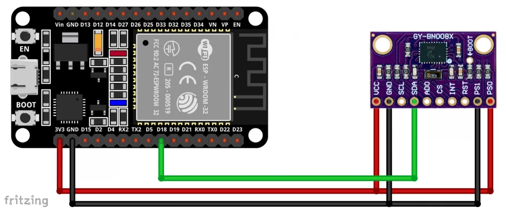
And here is the corresponding example sketch:
#include "Adafruit_BNO08x_RVC.h"

#define RX2 18
#define TX2 19

Adafruit_BNO08x_RVC rvc = Adafruit_BNO08x_RVC();

void setup() {
  // Wait for serial monitor to open
  Serial.begin(115200);
  Serial2.begin(115200, SERIAL_8N1, RX2, TX2);
  while (!Serial) delay(10);
  while (!Serial2) delay(10);

  Serial.println("Adafruit BNO08x IMU - UART-RVC mode");

  Serial1.begin(115200); // This is the baud rate specified by the datasheet
  while (!Serial1)
    delay(10);

  if (!rvc.begin(&Serial2)) { // connect to the sensor over hardware serial
    Serial.println("Could not find BNO08x!");
    while (1)
      delay(10);
  }

  Serial.println("BNO08x found!");
}

void loop() {
  BNO08x_RVC_Data heading;

  if (!rvc.read(&heading)) {
    return;
  }

  Serial.println();
  Serial.println(F("---------------------------------------"));
  Serial.println(F("Principal Axes:"));
  Serial.println(F("---------------------------------------"));
  Serial.print(F("Yaw: "));
  Serial.print(heading.yaw);
  Serial.print(F("\tPitch: "));
  Serial.print(heading.pitch);
  Serial.print(F("\tRoll: "));
  Serial.println(heading.roll);
  Serial.println(F("---------------------------------------"));
  Serial.println(F("Acceleration"));
  Serial.println(F("---------------------------------------"));
  Serial.print(F("X: "));
  Serial.print(heading.x_accel);
  Serial.print(F("\tY: "));
  Serial.print(heading.y_accel);
  Serial.print(F("\tZ: "));
  Serial.println(heading.z_accel);
  Serial.println(F("---------------------------------------"));


  //  delay(200);
}
Use of 5-volt boards using the example of the UNO R4 Minima
And finally, I wanted to show that you can, of course, also use 5-volt boards such as the Arduino UNO R4 Minima. If you don’t have a 5-volt-capable BNO08x module like the one from Adafruit, you’ll have to use a level shifter (e.g. the TXS0108E). Nevertheless, your microcontroller board must, of course, still meet the high demands on the RAM.
Here is an example of the circuit for an Arduino UNO R4 Minima with TXS0108E level shifter using SPI:
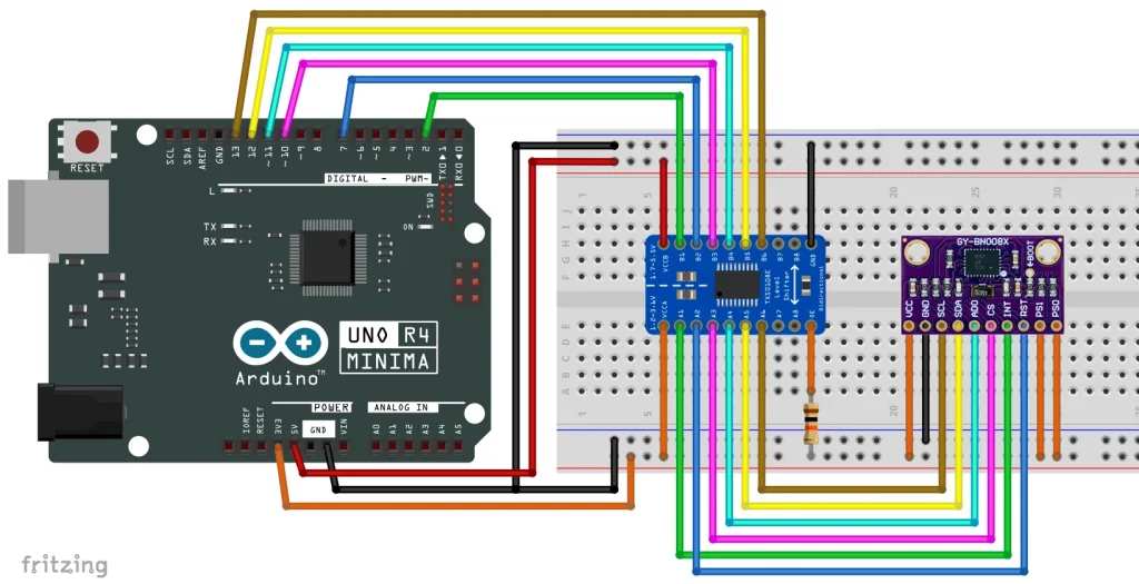
That is quite a lot of plugging or soldering work.
Acknowledgement
The coordinate cross in the foreground of my post image(link) comes from Clker-Free-Vector-Images on Pixabay.