
About this Post
In this article, I will show you how to use the MiniCore board package from MCUdude to program ATmega328, ATmega168, ATmega88, ATmega48 and ATmega8-based boards (e.g. Arduino UNO R3) as well as the bare ICs. The article is basically an extended new edition of my earlier article on standalone operation of the ATmega328P. Accordingly, the focus here is on the sketch upload, while the actual operation differs only in details from the use of the classic Arduino board package.
These are the topics I will discuss:
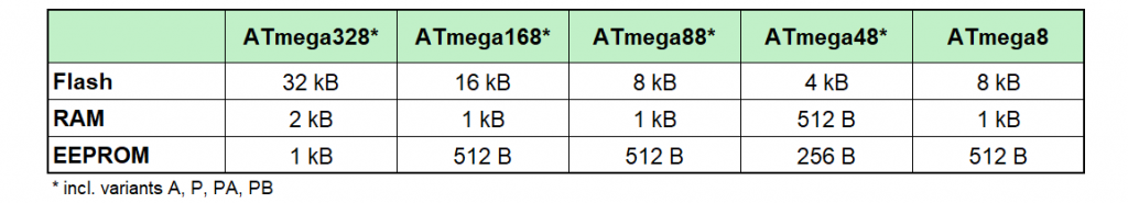
- Microcontrollers supported by MiniCore
- Why should I use MiniCore?
- Installing MiniCore
- ISP, bootloader and fuses
- Burning the Minicore boot loader (Urboot)
- Uploading sketches
- Using the ATmega328PB
- Appendix – Programmer
- Appendix – Wire timeout
Microcontrollers supported by MiniCore
You can program the following microcontrollers or the boards based on them with MiniCore:
Aren’t the ATmega microcontrollers discussed here long out of date? After all, the ATmega328 came onto the market almost 20 years ago, and even the newer variant, the ATmega328PB, is now around 10 years old. So, these microcontrollers are definitely not brand new – and compared to more modern representatives such as the ESP32 or the Renesas RA4M1 (Arduino UNO R4), they seem rather modest in terms of performance.
And yet: According to Microchip, they are still in production today (as of 03/26). The ATmega328P(B) in particular is still very popular. Hardly any other microcontroller has been covered so often in tutorials and articles – an enormous advantage if you get stuck.
From my point of view, these “classics” even have their very own appeal: they are ideal for beginners who want to leave the Arduino abstraction behind and delve deeper into working with registers. I also appreciate their extensive options for saving energy (see here and here)
Why should I use MiniCore?
On the one hand, you can use the MiniCore package as an alternative to the Arduino packages such as for the Arduino UNO R3, the classic Arduino Nano or the Arduino Pro Mini. It offers the following advantages, among others:
- Use of the faster and smaller Urboot bootloader.
- Flexibility with regard to the system clock.
printf()is implemented.- Various BOD options (brown-out detection), i.e. behavior at low voltage.
- EEPROM options: Erase/not erase when burning the bootloader.
- Freedom of choice for Link Time Optimization(LTO). LTO is a compiler optimization technique that can cause problems under certain conditions.
- Pin macros, such as
digitalWrite(PIN_PB5, HIGH); - Simplified sleep functions.
Secondly, the package is suitable for “standalone” programming of the microcontrollers discussed here. It is much more flexible than the package “ATmega328 on a breadboard”, which I used in the earlier article mentioned above.
Installing MiniCore
You can find detailed instructions on how to install third-party board packages here. I will limit myself to a quick guide:
- Open the Arduino IDE and go to File → Settings.
- Click on the button next to “Additional boards manager URLs”.
- Enter the following as an additional line: “https://mcudude.github.io/MiniCore/package_MCUdude_MiniCore_index.json” (without the quotation marks).
- Confirm twice with OK.
- Open the board management (symbol on the left side of the IDE) and search for “MiniCore”.
- Click on Install.
ISP, bootloader and fuses
First a little theory. Experienced users may want to skip this part!
There are various methods of programming a microcontroller. For AVR microcontrollers, programming via ISP (In-System Programming) or via bootloader are the most common methods.
Programming via ISP
While ISP programming is in progress, the microcontroller is kept in a reset state by the programmer. In this state, no sketch is started; instead, the controller activates its serial programming mode. Communication takes place via the SPI pins (MOSI, MISO and SCK).
The programmer first sends a special activation command. If the microcontroller responds correctly, it signals that it is ready for programming. This is followed by the upload to the flash memory. After completion, the programmer releases the RESET pin again so that the microcontroller restarts and executes the loaded program.
Programming via bootloader
After a reset or restart, the program counter jumps to the reset vector address. By default, this is at address 0x0000, where the user program begins. However, if the bootloader is activated (BOOTRST fuse set), the reset vector points to the bootloader section instead.
A bootloader is a small program that is located at the end of the flash memory. The memory space reserved for it is protected and reduces the available flash for the user program accordingly. If the microcontroller is reset or restarted, the reset vector – provided the corresponding fuse (BOOTRST) is set – does not point to address 0x0000, but to the start of the bootloader section.
Then, the bootloader briefly checks whether a program shall be uploaded via a serial interface (for Arduino: UART). If this is the case, it ensures the upload of the new program. Otherwise, it then jumps to the actual user program at address 0x0000.
The advantage of the bootloader method is that no programmer is required. Instead, a USB-to-TTL adapter must be available so that your USB interface can communicate with the UART interface of the microcontroller. However, such an adapter is required anyway if you want to communicate with the serial interface. Two birds with one stone.
Confusion with the fuses
The fuses already mentioned are located in a non-volatile memory area (i.e. they are retained after a restart) in the microcontroller and contain basic settings such as the clock source, the clock frequency, or whether a bootloader is present.
When you click “Burn Bootloader” in the Arduino IDE, not only is the bootloader itself uploaded, but the fuses are also set according to the settings in the Arduino IDE. If, on the other hand, you upload a program — whether via the bootloader or via ISP — the fuses are not adjusted. For example, if you change the clock speed in the settings and upload a blink program, the actual clock rate does not change, but the interpretation of how long a clock cycle is is no longer correct. And so your blink frequency is incorrect.
Deleting the bootloader
This is simple: You burn the bootloader with the “No Bootloader” option. However, the bootloader is also deleted if you upload a program via ISP. In this case, the entire flash memory is deleted first and with it the bootloader. But it is safer to burn the bootloader with the “No bootloader” option (see below).
Burning the Minicore boot loader (Urboot)
So, regardless of which board or microcontroller you want to use with MiniCore, and regardless of whether it has a bootloader or not, the first thing you need to do is burn the bootloader. And for this you need a programmer.
The good news is that you can turn an Arduino board into an ISP programmer. The bad news: This procedure is quite fiddly, and you can make mistakes in many places. I therefore recommend investing in a programmer. There are several available for just a few euros. In the appendix you will find a list of programmers that I have successfully tried out.
Arduino as ISP
But even if I recommend using a programmer, I would still like to show you here how to use an Arduino board as an AVR-ISP programmer. It doesn’t necessarily have to be an AVR-based board, but it’s the easiest way (here you can find information on other boards).
As an illustrative example, I will take the classic Arduino Nano and show you how to program an ATmega328P with it. Here is the pinout diagram of the ATmega328P, which is also essentially valid for the ATmega8/48/88/168 (details here):

- Step 1: Select the Arduino Nano (the programmer board) in the Arduino IDE and connect it to your PC. Make sure you select the correct port. It’s best to do this without connecting the Arduino to anything else.
- Step 2: Go to File → Examples → Built-in examples, open the ArduinoISP sketch, and upload it.
- Step 3: Connect the Arduino Nano to the ATmega328P as follows:
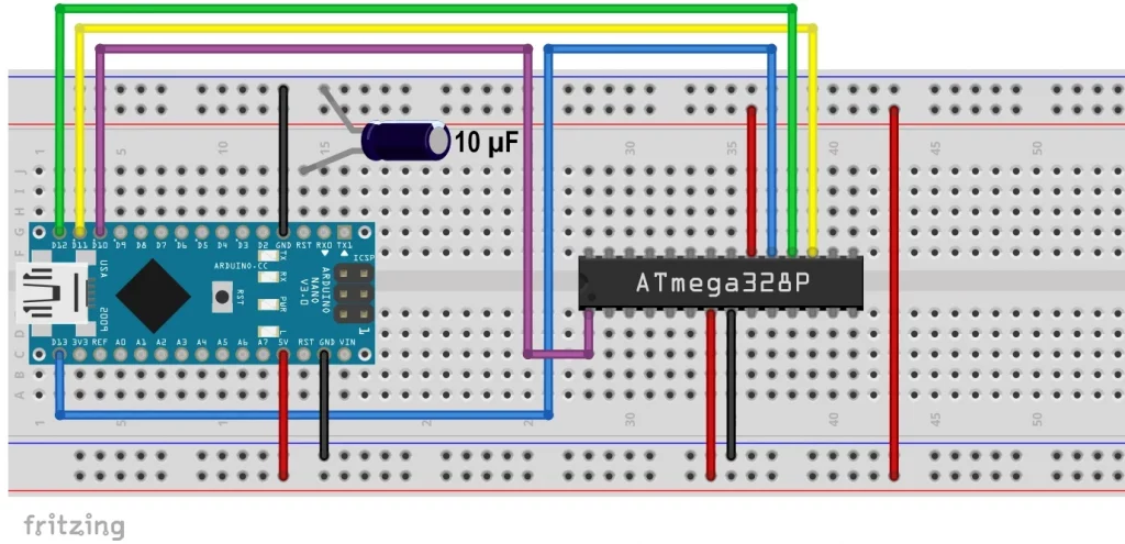
Without the 10 µF capacitor, the board-internal USB-to-TTL adapter would automatically trigger a reset of the Arduino Nano when starting an upload. This behavior is normally desired as it starts the bootloader. However, if the Arduino Nano itself is to serve as an ISP programmer, the ArduinoISP sketch must continue to run continuously and must not be interrupted by a reset.
The capacitor between RESET and GND prevents this automatic reset by intercepting the corresponding signals from the USB serial adapter (DTR/RTS). As a result, the Arduino remains stable during operation and can work reliably as a programmer.
Boards without a USB-to-TTL adapter do not require this capacitor.
If you want to upload the ArduinoISP sketch again for any reason, you will, of course, have to remove the capacitor.
- Step 4: Now select the MiniCore package and make the following settings for the ATmega328P (your target):
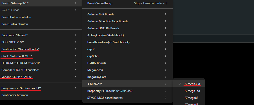
For the bootloader, you must select “Yes (UART0)” if you want to upload your sketches later via USB-to-TTL adapter. If you wish to upload the sketches via ISP, then you should select “No Bootloader”. If you are using an ATmega328PB, you can also select UART1.
When it comes to the clock rate, you need to think about what you need. External crystals are more accurate than the internal oscillator.
- Step 5: Click on “Burn Bootloader”.
And if you have done everything right, you will be rewarded with a success message.
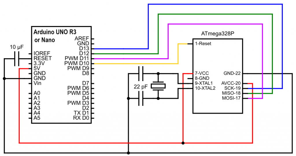
Using external oscillators
If you want to use an external oscillator, the circuit would look like this (a Fritzing diagram would be too confusing):
If you have accidentally set an external oscillator but none is connected, you have locked yourself out. You will need to attach one. Alternatively, you can use an Arduino UNO R3 with an ATmega328P in PDIP design, replace the ATmega328P, and flash the bootloader (using a programmer, of course).
Programmer Shield
If the wiring is too tedious for you and you have an Arduino UNO R3, then you can use such an AVR ISP shield:
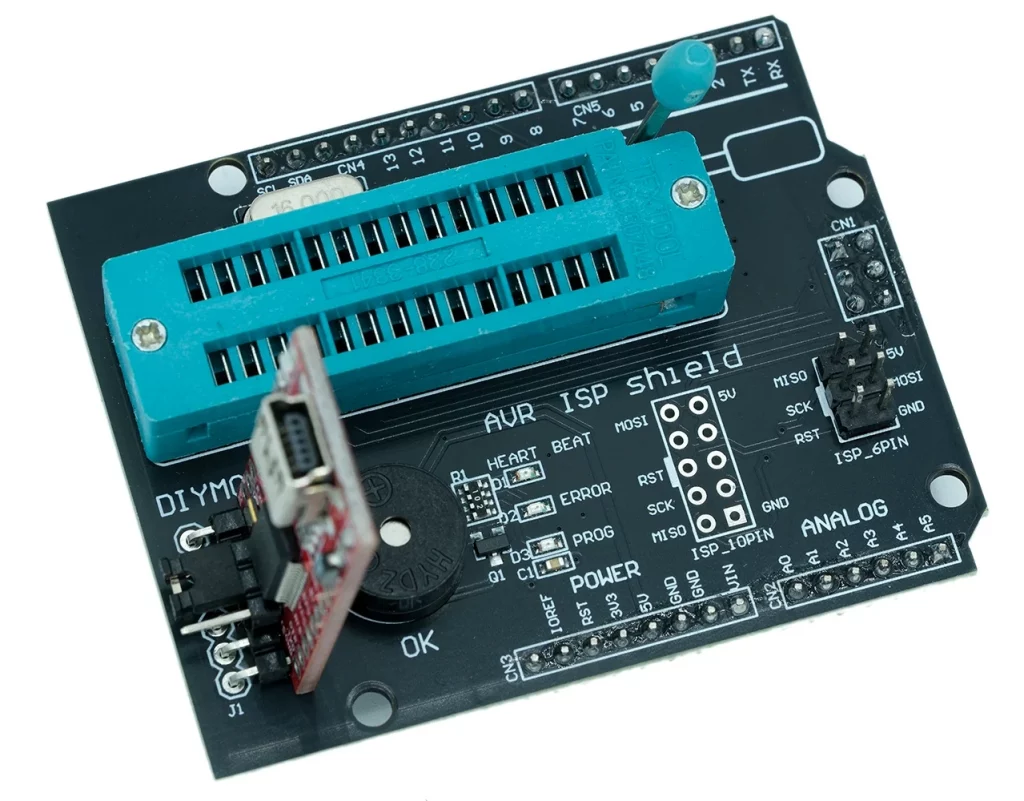
All you have to do is upload the ArduinoISP sketch to the Arduino, clamp the ATmega328P in the ZIF socket, place the shield on the Arduino and then you can burn the bootloader. The latter, of course, has to be done using the settings for the ATmega328P.
The USB-to-TTL adapter (below left in the photo) is not included in the scope of delivery. I also soldered it on so that I could upload sketches via bootloader.
If it does not work
You can do a lot of things wrong when using an Arduino as a programmer. Here is a small checklist:
- Wiring (the cables themselves can also be defective).
- The programmer board must be selected when uploading ArduinoISP.ino. The circuit is without the capacitor at Reset.
- When burning the bootloader to the target, the settings for the target board must be selected. In this case, the capacitor is needed.
- If you cannot burn the bootloader, it could be because an external oscillator is set in the fuses and you have not connected one → attach one and make the desired settings.
- With some programmers, including the Arduino as ISP, you have to set the port. There are also programmers that do not appear as serial devices.
Burn bootloader with a dedicated programmer
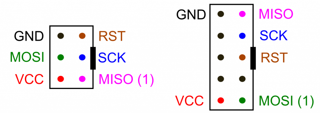
If you frequently flash bootloaders and upload sketches via ISP, I would recommend buying a “proper” programmer. You might have to spend a bit of time installing the drivers the first time round, but it’ll be easier for you after that. You’ll find a selection below. The programmers have a 6-pin and/or 10-pin output. Here is the pinout:
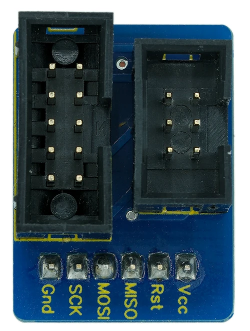
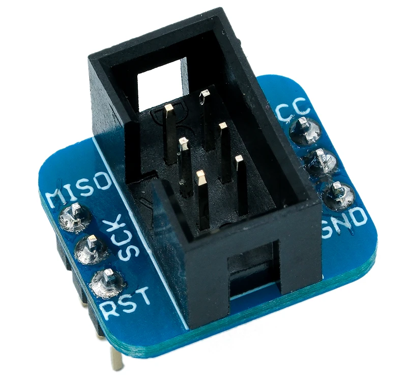
If you work a lot on the breadboard, I recommend a breakout adapter. This will reduce the risk of wiring errors.
On the left and right, you can see two common models.
The following board (approx. 7 € on AliExpress) is also very practical in combination with programmers. You simply put the ATmega328P into the ZIF socket and connect the programmer via the ISP connector (ICSP):
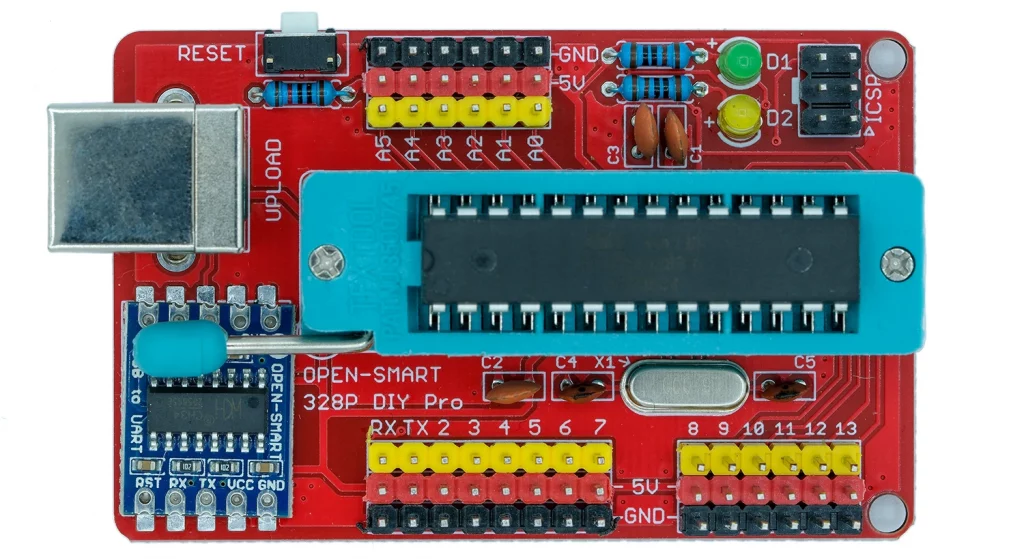
As it has a USB-to-TTL adapter, you can easily upload programs via the USB port later on. Essentially, this board is an Arduino UNO with a ZIF socket. Of course, you could simply use an Arduino UNO instead, but changing the microcontroller is much easier with the ZIF socket.
Circuit/settings for MiniCore in the Arduino IDE
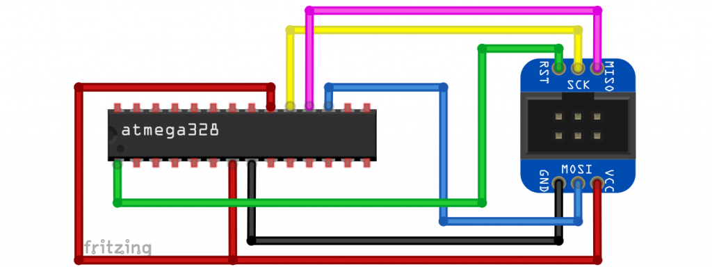
Burning the bootloader with a “real” programmer differs in two ways:
- You must select another programmer.
- The reset pin of the programmer is connected directly to the reset pin of the microcontroller or the board. It is even easier with boards with an ISP connector: Connect the ISP connectors of the programmer and board and that’s it.
Here is an example circuit with an ISP breakout adapter:
Burning bootloaders to boards
If you want to burn a bootloader to an Arduino board instead of an ATmega IC, the principle is the same. It would look like this for two Arduino UNO R3:
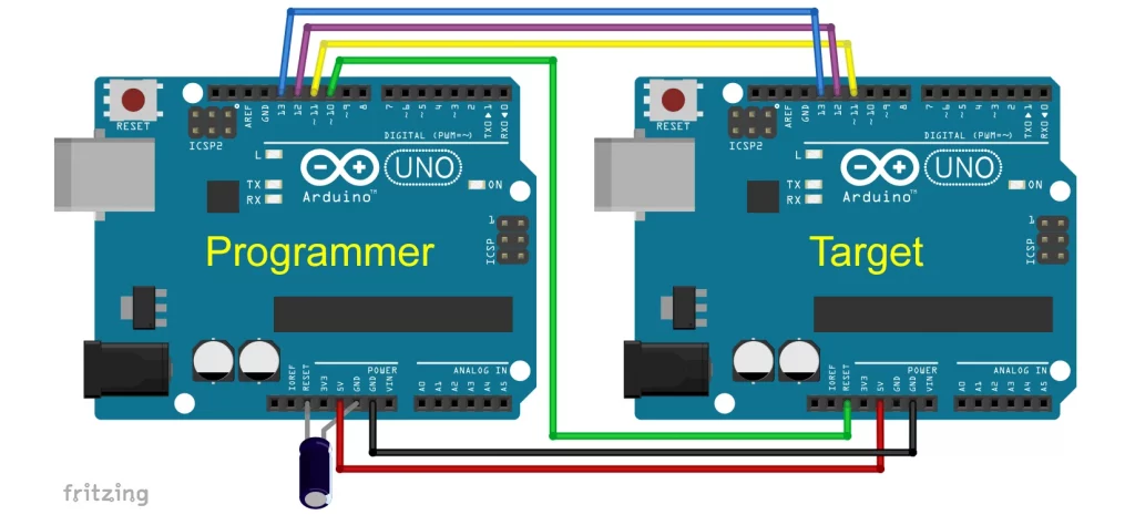
You cannot simply connect the ISP connectors here.
Uploading sketches
Sketchupload via ISP
Once you have managed to burn the bootloader, uploading sketches via the ISP is no longer a problem. You’ll keep the same settings in the Arduino IDE and the same connection to the programmer. Then simply select Sketch → “Upload via programmer” or use Ctrl + Shift + U. Clicking the arrow icon while pressing the Shift key does not work (reliably).
One disadvantage of the ISP method is that you also need a USB-to-TTL adapter to use the serial monitor. On the other hand, the advantage is that you have 384 bytes more flash available on an ATmega328P.
And even if I repeat myself: The bootloader (if present) is deleted when the program is uploaded via ISP.
Sketchupload via bootloader (serial)
USB-to-TTL adapter
To upload the program via the bootloader, you will first need a USB-to-TTL adapter. It’s sometimes also called an FTDI adapter, as chips from FTDI (Future Technology Devices International) were predominantly used in the past. Nowadays, many other chips are also used, such as the CH340 or CP2102.
In any case, you should get a model with a DTR pin (Data Terminal Ready). The DTR pin is used to reset the microcontroller before the actual upload. It is possible without DTR, but this is very impractical: you pull the microcontroller’s reset pin down to GND just before the actual upload. You can do this, for example, using a push button that you release at the right moment. As the time window is very short, it is correspondingly difficult to hit the target.
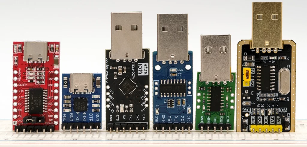
The model on the right does not have a DTR pin but an RTS pin (Ready to Send). Uploading with this component worked when I connected RTS directly to Reset, i.e. without the capacitor. With another model featuring an RTS pin (not shown here), the only way it worked was by connecting RTS to Reset via the capacitor.
Models with an FTDI chip, such as the one on the top left, have failed about three out of ten upload attempts. If this happens to you too, try it a few times. I don’t know the reason for the problem.
Wiring
Connect DTR to the microcontroller’s reset pin via a 100 nF capacitor. Also, connect a pull-up resistor to the reset pin. Connect RX to TX and TX to RX. Connect GND and VCC as usual.
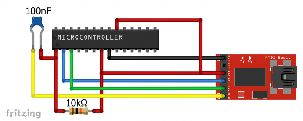
The capacitor can also be larger. It worked the same for me with a 10 µF electrolytic capacitor (minus on the DTR side).
Then you have to set the correct port and upload. This time without a programmer, i.e., via the green arrow, via Ctrl + U or using the menu.
Using the ATmega328PB with MiniCore
The ATmega328PB is certainly not a major innovation compared to the ATmega328P. Nevertheless – its additional UART, I²C and SPI interfaces or the two additional 16-bit timers could be exactly the features you need for a project.
If you are keen to know more about the ATmega328PB and boards based on it, take a look at this article of mine.
Appendix – Programmer
There are programmers in a wide range of price categories. The more expensive models can often do more than just upload via ISP. I have successfully tested all the models listed here. Before you can use the programmer, you will need to install a suitable driver for most of them.
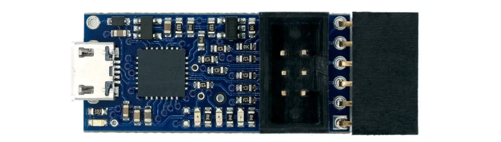
USBTinyISP
- AVR-ISP
- Installation: see below
- Amazon: from 10 €
- AliExpress: from 2 €
Tiny ISP / USBTinyISP / FabISP
This is probably the smallest and cheapest model.
- AVR-ISP
- Installation: see below
- Amazon: from 6 €
- AliExpress: from 1.5 €
USBASP
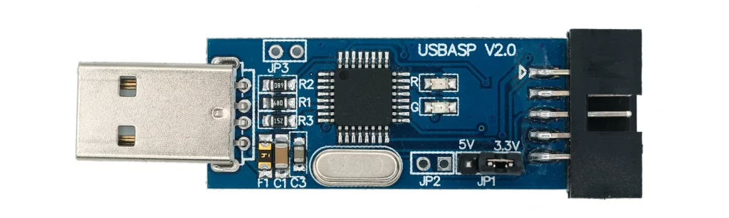
- AVR-ISP
- Installation: see below
- Amazon: from 10 €
- AliExpress: from 2 €
Note on use: the output is 10-pin. An adapter to ISP (6-pin) is usually supplied.
Pololu USB AVR Programmer V2
- AVR-ISP and USB-to-TTL adapter
- Detailed instructions: here
- Online electronics stores: ~ 18 €
This device serves both as an AVR-ISP programmer and a USB-to-TTL adapter. Another handy feature is that you can plug the adapter directly into an Arduino Pro Mini.
Diamex AVR-ISP Programmer
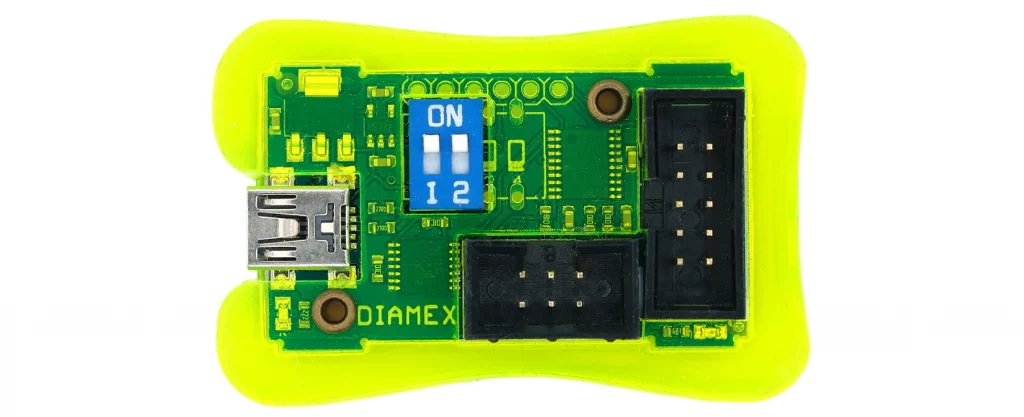
- AVR-ISP
- Detailed instructions: here
- Online electronics stores: from €22
Diamex EXA-PROG
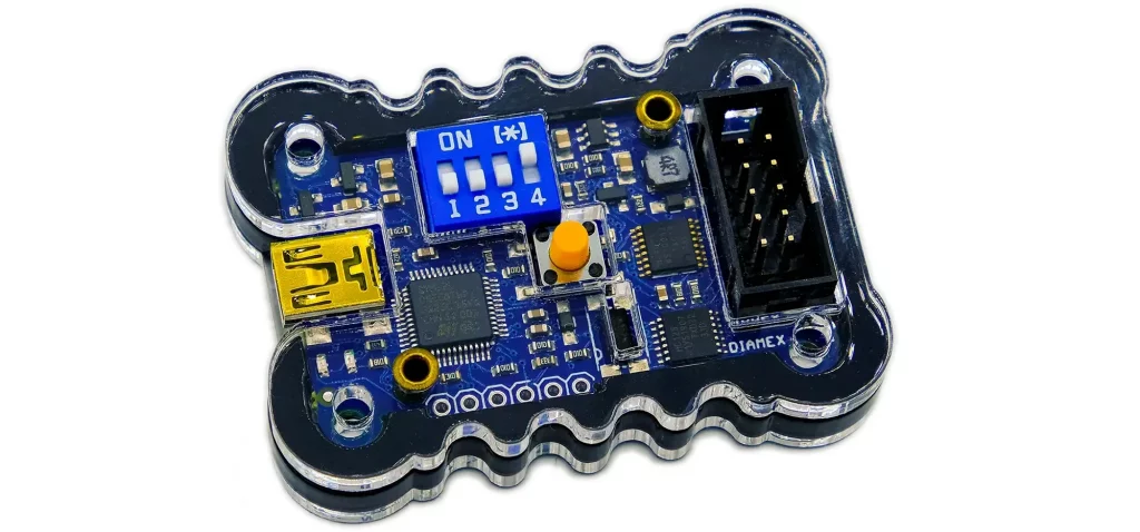
- AVR-ISP, UPDI / UPDI HV, STM32 (Cortex M), NXP (Cortex M), ESP32, ESP8266
- Detailed instructions: here.
- Online electronics stores: from €28
You should also get an adapter for 10-pin → 6-pin for this programmer. Alternatively, you can also use a suitable breadboard adapter.
Diamex has other programmers on offer.
ATMEL-ICE

- ISP, JTAG, SWD, UPDI, TPI, aWire, debugwire
- Detailed instructions: here.
- Online electronics stores: from €100 (basic version)
The ATMEL-ICE is certainly only for people who do a lot of programming. It is extremely fast and also well integrated into Microchip Studio. Apart from its price, however, I find it a disadvantage that it does not provide the operating voltage for the microcontroller to be programmed. Instead, the VCC line is used to check whether the microcontroller has a sufficient voltage level. I also don’t particularly like the small 10-pin 50-mil socket. An adapter cable to the usual 100-mil format is included, but this is very delicate and expensive to replace.
Driver installation using Zadig
Zadig is a small tool that makes it easy to install the drivers for some of the programmers listed above. You can download Zadig here. The program consists solely of an EXE file, which does not require an installation process. Simply save it somewhere you can find it again. And if you want to get rid of Zadig again, simply delete the EXE file in question.
After starting the program you will see the following:
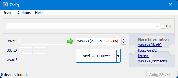
First, go to Options → List all Devices. Then open the drop-down menu and see everything that is connected to USB:
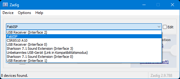
To ensure that you really select the device for which you want to change the driver, it is best to plug it in and out and see what appears or disappears in the list. Click on the entry (here e.g. FabISP):
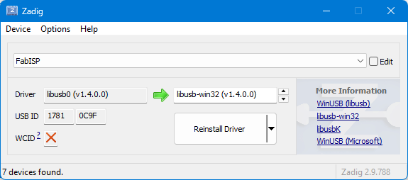
To the left of the green arrow, you can see which driver is currently installed (possibly “NONE”); to the right, you can select the driver that you want to install (instead). Then click on “Install Driver”, “Replace Driver” or “Reinstall Driver”, depending on your preference. But once again, make sure you select the correct device. Once, I was distracted enough to replace my mouse driver with Zadig. It’s not easy to get the right mouse driver back – without a mouse!
Here is the driver selection that worked for me:
- USBTinyISP: libusb-win32
- Tiny ISP / USBTinyISP / FabISP: libusb-win32
- USBAsp: WinUSB
Appendix – Wire timeout
The topic didn’t really fit into the other context, so I’ve added it here in the appendix. The functions setWireTimeout(), getWireTimeoutFlag() and clearWireTimeoutFlag() are deactivated by default in the MiniCore package. To change this, you must uncomment line 3 // #define WIRE_TIMEOUT in the Wire_timeout.h file. Where the file is located depends on your installation. For me it is under:
C:\Users\user\AppData\Local\Arduino15\packages\MiniCore\hardware\avr\version\libraries\Wire\src
How to support me
If you liked the article and would like to support me, then take a look here.