
About the post
In the last post I showed how to configure Bluetooth modules and use them to communicate from Arduino to Arduino. This article is now about the exciting topic of how to control Arduino boards with your smartphone. It is very easy to even implement voice control.
The article is divided into the following sections:
- “Finished solutions” using the example of the Ardroid app
- Communication via Bluetooth Terminal software
- Develop your own (Android) app with MIT App Inventor
Ardroid – a ready-made solution
There are a number of apps with which you can control your Arduino quite conveniently. The corresponding sketches are included and must or can usually be adapted a little. As an example, I present the Ardroid app, which you can download from Google Play. The app can control the Arduino digital and analog pins as well as send or receive text: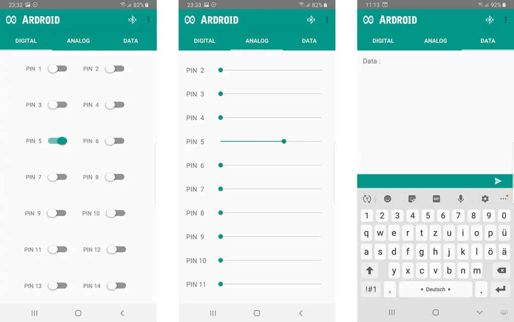
Preparations
On the Arduino side I use an HC-05 Bluetooth module, which must be configured as a slave. The default baud rate on the HC-05 is 38400. Accordingly, the baud rate in the sketch and on the serial monitor must be adjusted. Or you can change the baud rate of the HC-05 as described in my previous post.
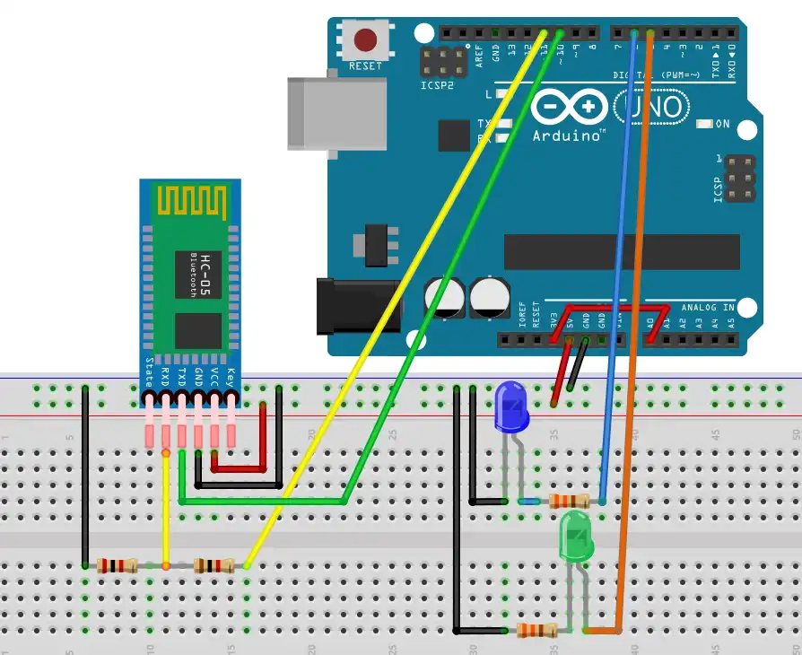
Since I am a comfortable person, I tested the Ardroid app with only two LEDs on pin 5 and 6. The circuit for this looks like this:

The voltage divider (1 k / 2 kΩ) I have added for correctness, because the RX pin on the HC-05 officially only tolerates 3.3 V. So far, however, I have consistently ignored this and have never had any problems with 5 V.
The 3.3 V connected to A0 only serve to read out a defined value at this input.
Pairing the HC-05 with your smartphone works like any other Bluetooth device. The pin must be entered once (default: 1234). Then you can connect to your module in the Ardroid app (Settings – > Paired Devices).
The Ardroid sketch
On Google Play (or here) you can get the corresponding sketch via a link. You only have to adjust the baud rate if necessary. When uploading the sketch, you will probably get an error message if the HC-05 is already connected to the RX Pin of the Arduino. Disconnect when uploading, then it works. Here’s what the included sketch looks like:
/*
 PROJECT: Ardroid
 CODED BY: Anurag Goel
 PUBLIC Licence Free To Modify
*/

#define START_CMD_CHAR '*'
#define END_CMD_CHAR '#'
#define DIV_CMD_CHAR '|'
#define CMD_DIGITALWRITE 10
#define CMD_ANALOGWRITE 11
#define CMD_TEXT 12
#define CMD_READ_ARDROID 13
#define MAX_COMMAND 20
#define MIN_COMMAND 10
#define IN_STRING_LENGHT 40
#define MAX_ANALOGWRITE 255
#define PIN_HIGH 3
#define PIN_LOW 2

String inText;

void setup() {
  Serial.begin(38400);
  Serial.println("Ardroid By : Anurag Goel");
  Serial.flush();
}

void loop()
{
  Serial.flush();
  int ard_command = 0;
  int pin_num = 0;
  int pin_value = 0;

  char get_char = ' ';  //read serial

  // wait for incoming data
  if (Serial.available() < 1) return; // if serial empty, return to loop().

  // parse incoming command start flag
  get_char = Serial.read();
  if (get_char != START_CMD_CHAR) return; // if no command start flag, return to loop().

  // parse incoming command type
  ard_command = Serial.parseInt(); // read the command
  // parse incoming pin# and value
  pin_num = Serial.parseInt(); // read the pin
  pin_value = Serial.parseInt();  // read the value
  // 1) GET TEXT COMMAND FROM ARDROID
  if (ard_command == CMD_TEXT){
    inText =""; //clears variable for new input
    while (Serial.available())  {
   char c = Serial.read();

     //gets one byte from serial buffer
      delay(5);
      if (c == END_CMD_CHAR) { // if we the complete string has been read
        // add your code here
        Serial.println(inText);
        break;
      }
      else {
        if (c !=  DIV_CMD_CHAR) {
          inText += c;
          delay(5);
        }
      }
    }
  }

  // 2) GET digitalWrite DATA FROM ARDROID
  if (ard_command == CMD_DIGITALWRITE){
    if (pin_value == PIN_LOW) pin_value = LOW;
    else if (pin_value == PIN_HIGH) pin_value = HIGH;
    else return; // error in pin value. return.
    set_digitalwrite( pin_num,  pin_value);
    return;  // return from start of loop()
  }

  // 3) GET analogWrite DATA FROM ARDROID
  if (ard_command == CMD_ANALOGWRITE) {
    analogWrite(  pin_num, pin_value );
    // add your code here
    return;  // Done. return to loop();
  }

  // 4) SEND DATA TO ARDROID
  if (ard_command == CMD_READ_ARDROID) {
//    char send_to_android[] = "Place your text here." ;
//    Serial.println(send_to_android);   // Example: Sending text
    Serial.print(" Analog 0 = ");
    Serial.println(analogRead(A0));  // Example: Read and send Analog pin value to Arduino
    return;  // Done. return to loop();
  }
}

// 2a) select the requested pin# for DigitalWrite action
void set_digitalwrite(int pin_num, int pin_value)
{
  switch (pin_num) {
  case 13:
    pinMode(13, OUTPUT);
    digitalWrite(13, pin_value);
    // add your code here
    break;
  case 12:
    pinMode(12, OUTPUT);
    digitalWrite(12, pin_value);
    // add your code here
    break;
  case 11:
    pinMode(11, OUTPUT);
    digitalWrite(11, pin_value);
    // add your code here
    break;
  case 10:
    pinMode(10, OUTPUT);
    digitalWrite(10, pin_value);
    // add your code here
    break;
  case 9:
    pinMode(9, OUTPUT);
    digitalWrite(9, pin_value);
    // add your code here
    break;
  case 8:
    pinMode(8, OUTPUT);
    digitalWrite(8, pin_value);
    // add your code here
    break;
  case 7:
    pinMode(7, OUTPUT);
    digitalWrite(7, pin_value);
    // add your code here
    break;
  case 6:
    pinMode(6, OUTPUT);
    digitalWrite(6, pin_value);
    // add your code here
    break;
  case 5:
    pinMode(5, OUTPUT);
    digitalWrite(5, pin_value);
    // add your code here
    break;
  case 4:
    pinMode(4, OUTPUT);
    digitalWrite(4, pin_value);
    // add your code here
    break;
  case 3:
    pinMode(3, OUTPUT);
    digitalWrite(3, pin_value);
    // add your code here
    break;
  case 2:
    pinMode(2, OUTPUT);
    digitalWrite(2, pin_value);
    // add your code here
    break;

  }
}
parseInt() commands, which is a very convenient method.
There are four commands: one for digitalWrite, one for analogWrite, one for sending text and one “multi-purpose” (CMD_READ_ARDROID), which is used here to read A0 by an analogRead command.
Switching and dimming the LEDs (= > sections “DIGITAL” and “ANALOG” in the Ardroid app) works very well. However, section “DATA” is apparently not quite mature yet. It is necessary to precede the text to be sent with a *any_number*any_number. So e.g.:
*1*1Text returns the output “Text” on the serial monitor
The function for reading A0 is apparently not working. This can be “repaired”, and will come to that soon. In addition, this part of the article serves anyway primarily as an introduction to the development of our own app which enables full control.
Bluetooth terminal
In the next step, I leave the Arduino page with the Ardroid Sketch unchanged, but replace the Ardroid app with the Bluetooth Terminalapp. With this very simple app you can easily understand how the Ardroid app works behind the scenes. Of course, a connection to the HC-05 must first be established in this app (setting – > Connect a device – Secure or – Insecure). In order to get rid of the blank lines when output in the serial monitor, you can deactivate “Append newline (\r\n)” in the app settings.
For example, to switch on the LED connected to pin 5, you send:
*10bla5blabla3 or more simple: *10*5*3 (encoding: see #define definitions in the sketch)
Important is the first character “*” and that three numbers are included. The characters in between are ignored. For example, to make the LED at pin 6 to the faintly low, you send:
*11*6*30
To get text to the serial monitor:
*12*9*9Gruß vom Smartphone#
So you have to enter three numbers here as well because the sketch uses three parseInt() commands. However, in this case the value of the back two numbers doesn’t matter. Again, the final hash is important because this is the cancellation condition for reading the string.
For triggering the analogRead function, a simple
*13
is sufficient.
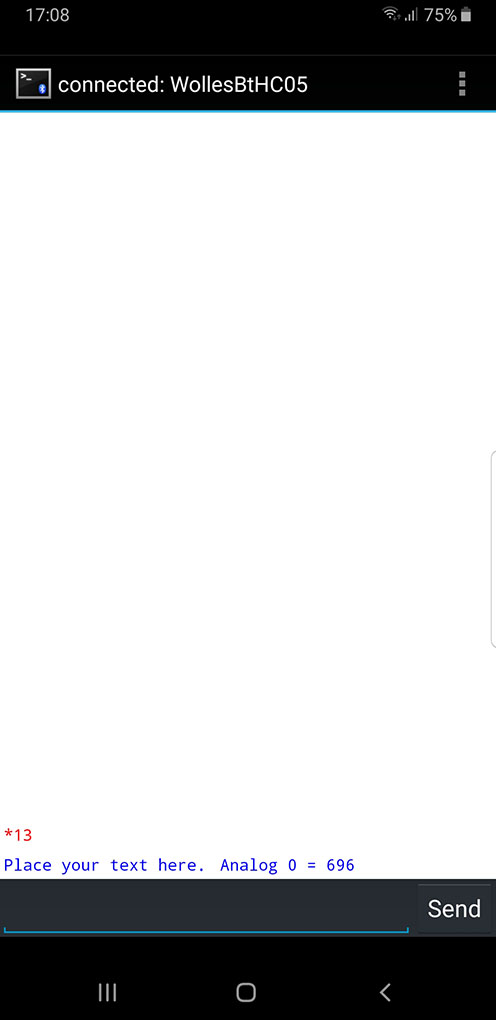
“Repair” of the Ardroid sketch
With this knowledge, the Ardroid sketch can also be modified (see below), so that you can send texts as well as read A0 in the section “DATA” of the Ardroid app. Or you can add other functions. When using this sketch, you set a *1*1 in the DATA app area before the text to be sent or a *2*1 if you want to read A0. I do not want to make the post too long, so I do not discuss this in detail. If you have any questions: ask!
/*
 PROJECT: Ardroid
 CODED BY: Anurag Goel
 PUBLIC Licence Free To Modify

 Modified by Wolfgang Ewald
*/

#define START_CMD_CHAR '*'
#define END_CMD_CHAR '#'
#define DIV_CMD_CHAR '|'
#define CMD_DIGITALWRITE 10
#define CMD_ANALOGWRITE 11
#define CMD_TEXT 12
#define CMD_READ_ARDROID 13
#define MAX_COMMAND 20
#define MIN_COMMAND 10
#define IN_STRING_LENGHT 40
#define MAX_ANALOGWRITE 255
#define PIN_HIGH 3
#define PIN_LOW 2

String inText;

void setup() {
  Serial.begin(38400);
  Serial.println("Ardroid By : Anurag Goel");
  Serial.flush();
}

void loop()
{
  Serial.flush();
  int ard_command = 0;
  int pin_num = 0;
  int pin_value = 0;

  char get_char = ' ';  //read serial

  // wait for incoming data
  if (Serial.available() < 1) return; // if serial empty, return to loop().

  // parse incoming command start flag
  get_char = Serial.read();
  if (get_char != START_CMD_CHAR) return; // if no command start flag, return to loop().

  // parse incoming command type
  ard_command = Serial.parseInt(); // read the command
  // parse incoming pin# and value
  pin_num = Serial.parseInt(); // read the pin
  pin_value = Serial.parseInt();  // read the value
  // 1) GET TEXT COMMAND FROM ARDROID
  if (ard_command == CMD_TEXT){
    if(pin_num == 1){
      inText =""; //clears variable for new input
      while (Serial.available())  {
      char c = Serial.read();

       //gets one byte from serial buffer
        delay(5);
        if (c == END_CMD_CHAR) { // if we the complete string has been read
          // add your code here
          Serial.println(inText);
          break;
        }
        else {
          if (c !=  DIV_CMD_CHAR) {
            inText += c;
            delay(5);
          }
        }
      }
    }
    if(pin_num == 2){
      char send_to_android[] = "Hello" ;
      Serial.println(send_to_android);   // Example: Sending text
      Serial.print(" Analog 0 = ");
      Serial.println(analogRead(A0));  // Example: Read and send Analog pin value to Arduino
      return;
    }
  }

  // 2) GET digitalWrite DATA FROM ARDROID
  if (ard_command == CMD_DIGITALWRITE){
    if (pin_value == PIN_LOW) pin_value = LOW;
    else if (pin_value == PIN_HIGH) pin_value = HIGH;
    else return; // error in pin value. return.
    set_digitalwrite( pin_num,  pin_value);
    return;  // return from start of loop()
  }

  // 3) GET analogWrite DATA FROM ARDROID
  if (ard_command == CMD_ANALOGWRITE) {
    analogWrite(  pin_num, pin_value );
    // add your code here
    return;  // Done. return to loop();
  }
}

// 2a) select the requested pin# for DigitalWrite action
void set_digitalwrite(int pin_num, int pin_value)
{
  switch (pin_num) {
  case 13:
    pinMode(13, OUTPUT);
    digitalWrite(13, pin_value);
    // add your code here
    break;
  case 12:
    pinMode(12, OUTPUT);
    digitalWrite(12, pin_value);
    // add your code here
    break;
  case 11:
    pinMode(11, OUTPUT);
    digitalWrite(11, pin_value);
    // add your code here
    break;
  case 10:
    pinMode(10, OUTPUT);
    digitalWrite(10, pin_value);
    // add your code here
    break;
  case 9:
    pinMode(9, OUTPUT);
    digitalWrite(9, pin_value);
    // add your code here
    break;
  case 8:
    pinMode(8, OUTPUT);
    digitalWrite(8, pin_value);
    // add your code here
    break;
  case 7:
    pinMode(7, OUTPUT);
    digitalWrite(7, pin_value);
    // add your code here
    break;
  case 6:
    pinMode(6, OUTPUT);
    digitalWrite(6, pin_value);
    // add your code here
    break;
  case 5:
    pinMode(5, OUTPUT);
    digitalWrite(5, pin_value);
    // add your code here
    break;
  case 4:
    pinMode(4, OUTPUT);
    digitalWrite(4, pin_value);
    // add your code here
    break;
  case 3:
    pinMode(3, OUTPUT);
    digitalWrite(3, pin_value);
    // add your code here
    break;
  case 2:
    pinMode(2, OUTPUT);
    digitalWrite(2, pin_value);
    // add your code here
    break;

  }
}
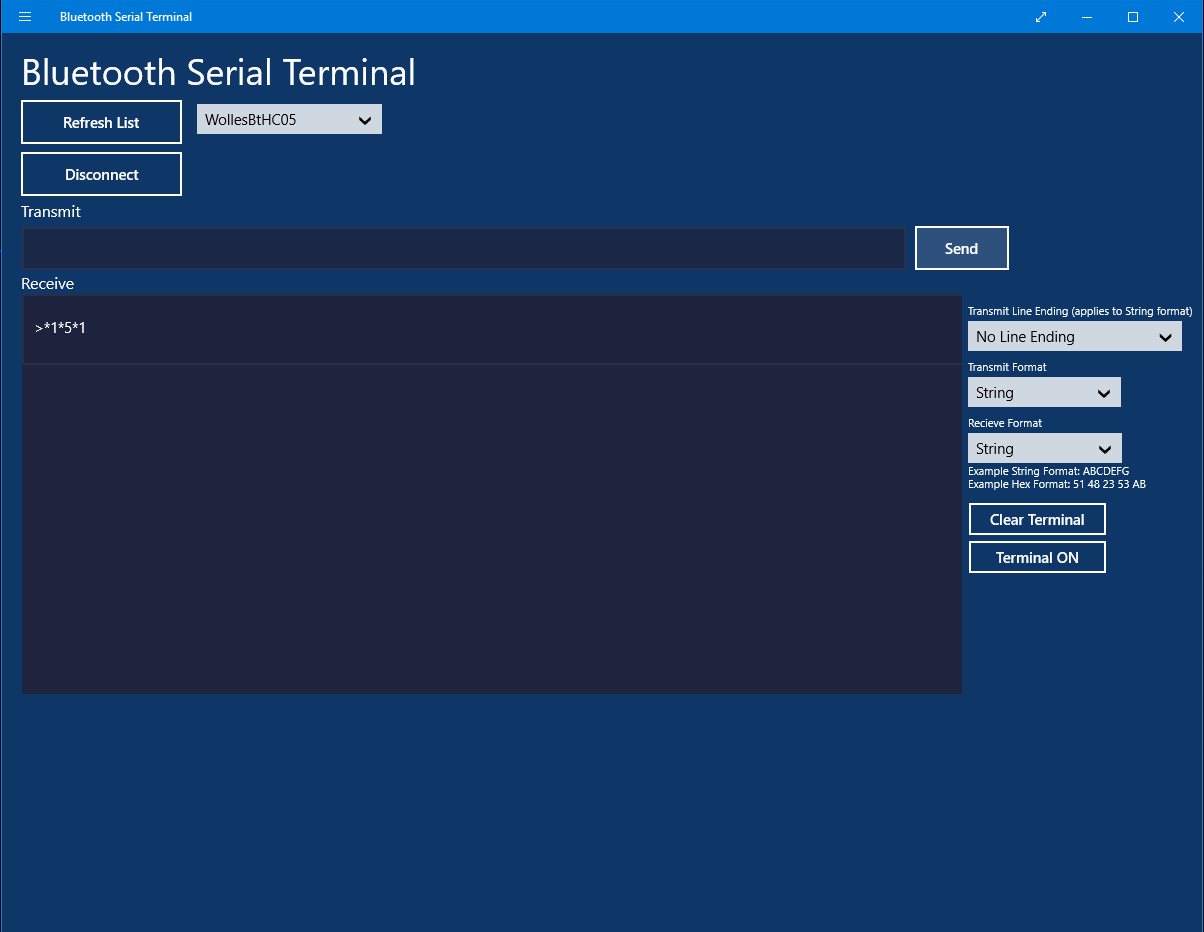
Control via PC
You can also control it via the PC. For this purpose, for example, you can use the freewareBluetooth Serial Terminal, which is very similar to the previously discussed smartphone app. You need a Bluetooth adapter, you have to activate it in the Windows settings, make the pairing and finally connect the PC to the module in the program. The rest works as described above for the smartphone.
Develop an app with MIT App Inventor
Preparation on the Arduino side
I modified the Ardroid sketch for the development of my own app, shortened it and called it “bt_receiver.ino”. Among other things, I have changed:
- SoftwareSerial replaces hardware serial (avoids upload issues described above)
- the commands I have defined as enum
- the reading of a text message is done via a simple
readString() - I have removed the long case construct
- “High” and “Low” statements are transmitted directly and not encoded
Apart from that, the sketch should be self-explanatory. The strings to be transmitted look a little different, here are a few examples:
*1*5*1 –> Pin 5 HIGH
*2*6*100 –> analogWrite PIN 6, value 100
*3Hallo — > outputs “Hallo” on the serial monitor
*4 — > analogRead of PIN 0 and send the result
It should also be noted that the baud rate on the serial monitor must be set to 9600 and that RX and TX of the Arduino are now pin 10 and 11.
#include <SoftwareSerial.h>
#define START_CMD_CHAR '*'

SoftwareSerial mySerial(10, 11);
enum command {DIGITALWRITE=1, ANALOGWRITE, DISPL_TXT_MSG, EXEC_TASK};

void setup() {
  Serial.begin(9600);
  mySerial.begin(38400);
  Serial.println("Bluetooth Empfänger bereit");
}

void loop(){

  if(mySerial.available()){
    analyzeMsg();
  }
}

void analyzeMsg(){
  int cmdType;
  int pinNum, pinValue = 0;
  char getChar = ' ';  //read serial

  getChar = mySerial.read();
  if(getChar != START_CMD_CHAR) return;
  cmdType = mySerial.parseInt(); // read the command

  if(cmdType==DIGITALWRITE){
    pinNum = mySerial.parseInt();
    pinValue = mySerial.parseInt();
    pinMode(pinNum, OUTPUT);
    digitalWrite(pinNum, pinValue);
  }

  if(cmdType==ANALOGWRITE){
    pinNum = mySerial.parseInt();
    pinValue = mySerial.parseInt();
    pinMode(pinNum, OUTPUT);
    analogWrite(pinNum, pinValue);
  }

  if(cmdType==DISPL_TXT_MSG){
    String msg = mySerial.readString();
    Serial.println(msg);
  }

  if(cmdType==EXEC_TASK){
    execTask();
  }
}

void execTask(){
  int value = analogRead(A0);
  mySerial.print("Analog 0 = ");
  mySerial.println(value);
}
Developing smartphone apps
Programming smartphone apps is nothing you can learn by the way. If you really want to deep-dive into this topic, you should learn Java and deal with development environments like Eclipse or Android Studio. The good news is that there is a simple alternative that is completely sufficient for our purposes and that is called MIT App Inventor. If you follow this link, you will get a lot of information about who is behind this project, how it works, which tutorials tare available (highly recommended as an introduction) and much more. A step-by-step guide would go beyond the scope of this post, but I will try to convey the essential points to you.
The goal: your own app for Arduino control
I’ll just start with the result to hopefully arouse your interest. I have developed a small app called “Arduino BT Control” that includes all the functions of the Ardroid app and also includes voice control (!). Since I am – as already mentioned – comfortable, I have limited myself to two pins regarding the pin control. But you can easily expand that. So, this is what the app looks like:
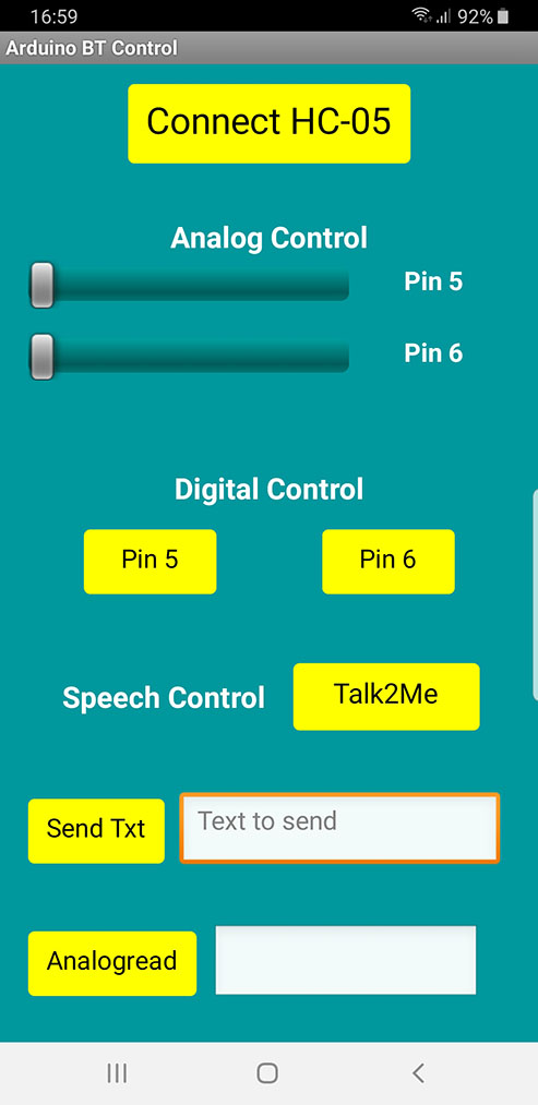
The large button “Connect HC-05” connects to the HC-05. “Analog Control” and “Digital Control” are self-self-explanatory. “Talk2Me” starts the voice control, e.g. you can turn on an LED with a spoken “pin fünf an” (sorry – it speaks German). “SendTxt” sends text to the serial monitor, “Analogread” queries pin A0.
On the Arduino side, as already mentioned, the bt_receiver.ino Sketch is used (see above).
How does MIT App Inventor work?
First of all, MIT App Inventor is an online solution, i.e. no program installation is required on your PC. One does not write a single program line during app development, but constructs program blocks visually from prefabricated individual parts. If you’ve ever worked with Scratch, you’ll find yourself here quickly.
What is particularly cool is that you can follow the creation of your apps in real time on your smartphone. This applies to both design and functionality. It is not necessary to compile code in between and beam apk files to the smartphone. You don’t do that until you’re satisfied with your result and the app is supposed to run independently of the development environment.
To connect the smartphone to MIT App Inventor, you must first install the APP MIT AI2 Companion. MIT App Inventor then provides a number or QR code for the connection. Very convenient! I had some problems using Edge, but Chrome worked well.
Click on this link to get to the programming interface and log in with your Google Account.
The Designer Screen
As mentioned, I can’t provide step-by-step instructions here, and just explain the concept. Essentially, the app development consists of two steps, namely the design and the definition of the functions behind the design. For this purpose there are two screens between which you can switch, namely “Designer” and “Blocks”. The Designer screen looks like this for the Arduino BT Control app:
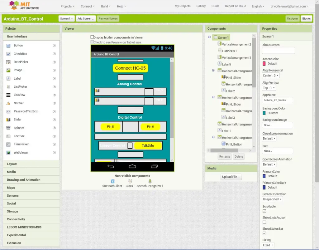
On the left side you see the menu for the different elements that can be inserted. In the submenu “User Interface” you find buttons, checkboxes, sliders, etc. Under “Layout” you find elements such as horizontal and vertical arrangements. Bluetooth can be found under Connectivity. Just take a look.
The Components window reflects the structure of the components. Here you can also rename components, which is absolutely advisable, so as not to lose track. For example, “Pin5_Slider” makes more sense than the pre-set “Slider1”.
In the “Properties” window you can define the properties of the components, e.g. shape, color or which values are displayed for the sliders. For example, for an analogRead slider, you might want to specify a range from 0 to 255.
The Blocks screen
The components assembled in the Designer screen can’t do anything at first. What they trigger and under what conditions or how they should change is specified in the Blocks screen:
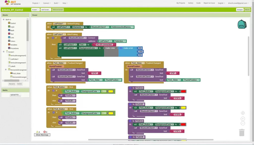
In the “Blocks” window, you can click on one of the components to get a selection of different blocks to choose from. The selected block will be transferred into the viewer window where it can be moved freely. For example, because a slider can only do certain things, only the corresponding blocks are suggested. This allows you to work quite intuitively and quickly. In addition, under “Built-In” there are general blocks e.g. for text, if-then-else constructs and much more.
Another help is that the blocks are shaped like puzzle pieces. As a result, only certain components fit together and everything must be completed. This avoids syntax errors, but you have to pay attention to the logic errors yourself.
Install the developed app
Finally, you can generate an apk file under the menu item “Build”, which can be conveniently transferred to the smartphone via a QR code.
The project is stored online. You can also export it as an “.aia” file, save it to your PC, share it with others, and then import it again. You can download the “.aia” file for the Arduino BT Control app presented here (follow the link and then click on the download icon on the right) and customize it to your liking. Alternatively, you can find the project in the gallery of MIT App Inventor if you click on this Link .
After a short period of getting used to it, you will quickly become familiar with MIT App Inventor. I think it’s a brilliant invention and hope you enjoy it as much as I do.