About the article
With this third part, I conclude my series on EEPROMs. In the two previous parts I had focused on the internal EEPROMs of the AVR boards and the external, I2C-based EEPROMs. This post is now about the external, SPI-based EEPROMs.
Why another separate article about SPI EEPROMs? Can the faster SPI transfer rate be leveraged at all with respect to the slow EEPROM write process? To anticipate: The high SPI speed is not so relevant. When transferring larger amounts of data in bulk (page write), however, it is noticeable that the 32-byte limitation of the I2C transfer is not present here. This allows you to use the entire page size of the EEPROM.
attributes
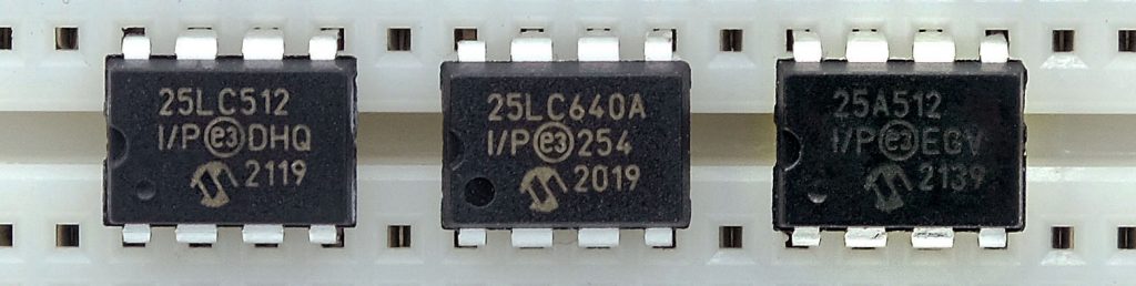
The SPI EEPROMs can be recognized by the fact that they have a 25 in their component name. The number (2n) after the letters indicates the memory size in kilobits. Here are a few examples:
I will not go into the general basics of EEPROMs again. I have already written a lot about this in parts 1 and 2 of this series.
Pinout
Typically, the SPI EEPROMs have the following pins:
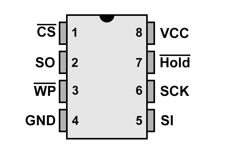
- CS: Chip Select, active-low.
- SO: Slave Out, to connect to MISO.
- WP: Write Protect, active-low.
- Works only in combination with the WPEN bit (unlike the 24 series)
- GND (VSS) / VCC: Power supply.
- “LC/C” variants are usually tolerant up to 5.5 volts, while “A” variants are limited to 3 volts.
- Hold: Hold pin, active-low, pauses the data transfer.
- SCK: SPI Clock, to connect to SCK.
- SI: Slave input, to connect to MOSI.
Connection to the microcontroller
As an example, I show how you connect the SPI-based EEPROM, provided it can tolerate 5 volts, with an Arduino Nano:
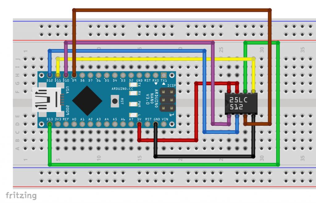
I use the HOLD-pin in only one example. Since probably few of you will use the feature, I connected it to VCC here. If you do not have enough pins available, you can also set the WP pin to HIGH.
Page Writing
The memory of an EEPROM is divided into pages. The pages usually have a size of 16, 32, 64 or 128 bytes. You can find this value in the data sheet.
Writing to EEPROMs is a very slow process. If you write a single byte to the EEPROM, you need the so-called “Write Cycle Time”, which is usually specified as 5 milliseconds. To speed up writing, the EEPROMs have a buffer memory the size of the pages. You can write this “in one go” (burst or bulk write). From this buffer memory, the individual memory addresses can be written to in parallel. This increases the write speed by a factor that is at most equal to the page size (in bytes).
The boundaries of the pages are fixed, and you are not allowed to write beyond them in burst write. I discussed this quite intensively in the last post.
Writing and reading SPI EEPROMs without library
Let’s get started. First, I’ll show you how to write to and read from SPI EEPROMs without a library. If you’re not interested, you can skip this section.
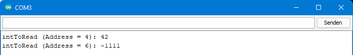
In this simple example, we write two integer values to EEPROM addresses 4 and 6 and then read them out.
I will not go into the basic SPI functions in this post. If necessary, you will find a brief introduction here.
Here is the sketch:
#include <SPI.h>
#define READ 0x03
#define WRITE 0x02
#define WREN 0x06  // write enable

const int csPin = 10;
const int wpPin = 9; // For this sketch you could also leave the wpPin unconnected
const int writeCycle = 5;

void setup(){
  pinMode(csPin, OUTPUT);
  digitalWrite(csPin, HIGH);
  pinMode(wpPin, OUTPUT);
  digitalWrite(wpPin,HIGH);
  SPI.begin();
  Serial.begin(9600);

  int16_t intToWrite = 4242;
  eepromWriteInt(4, intToWrite);
  intToWrite = -1111;
  eepromWriteInt(6, intToWrite);

  int16_t intToRead = 0;
  intToRead = eepromReadInt(4);
  Serial.print("intToRead (Address = 4): ");
  Serial.println(intToRead);
  intToRead = 0;
  intToRead = eepromReadInt(6);
  Serial.print("intToRead (Address = 6): ");
  Serial.println(intToRead);
}

void loop(){}

void eepromWriteEnable(){
  digitalWrite(csPin, LOW);
  SPI.transfer(WREN);
  digitalWrite(csPin, HIGH);
}

void eepromWriteInt(int addr, int16_t value){
  eepromWriteEnable();
  // If you want to change the SPI clock speed, uncomment the following line and adjust
  //SPI.beginTransaction(SPISettings(4000000, MSBFIRST, SPI_MODE0));
  digitalWrite(csPin, LOW);
  SPI.transfer(WRITE);
  SPI.transfer((uint8_t)(addr>>8));
  SPI.transfer((uint8_t)(addr&0xFF));
  SPI.transfer((uint8_t)(value>>8));
  SPI.transfer((uint8_t)(value&0xFF));
  digitalWrite(csPin, HIGH);
  //SPI.endTransaction(); // Uncomment if you have uncommented SPI.beginTransaction()
  delay(writeCycle);
}

int16_t eepromReadInt(int addr){
  byte MSB = 0;
  byte LSB = 0;
  int16_t value = 0;
  //SPI.beginTransaction(SPISettings(4000000, MSBFIRST, SPI_MODE0));
  digitalWrite(csPin, LOW);
  SPI.transfer(READ);
  SPI.transfer((uint8_t)(addr>>8));
  SPI.transfer((uint8_t)(addr&0xFF));
  MSB = SPI.transfer(0x00);
  LSB = SPI.transfer(0x00);
  digitalWrite(csPin, HIGH);
  //SPI.endTransaction();
  value = (int16_t)((MSB<<8)|LSB);
  return value;
}
And here is the expected output:
Just a few explanations:
- Integers of type
inthave different sizes on different boards, e.g. 2 bytes on AVR Arduinos and 4 bytes on ESP32 boards. However, as the size is important here, I useint16_tin this sketch. This sets the size to 2 bytes. - The SPI EEPOMs “understand” up to eleven different instructions. The sketch uses three of them:
- WREN (Write Enable): Sets the write enable bit in the status register of the EEPROM. After a successful write process, the bit is disabled.
- WRITE: Initiates the write operation.
- READ: Initiates the read operation.
- After sending the data to be written, i.e. each time the chip select pin goes HIGH again, you must wait for the write cycle time.
- The sketch only works for EEPROMs smaller than 1024 kB, as the three bytes are required for addressing once this limit is reached.
- The sketch won’t work either if you split an integer value across two pages. Try it out: For example, if the page size of your SPI EEPROM is 128 bytes, then write an integer to the address 127. When reading, you get an incorrect value.
The last two points mentioned are not the only flaw in the sketch. If you use other variable types such as strings, floats or arrays instead of integer values, you will need to adapt it accordingly. In addition, there are several features such as write protection and the hold function that have not yet been considered here. All das kann ergänzt werden, der einfachere Weg geht jedoch über eine Bibliothek.
Library for SPI EEPROMs
My library EEPROM_SPI_WE can be found here on GitHub, or you can install it via the library manager of the Arduino IDE. Using a few example sketches, I introduce its functions. The example sketches are part of the library, so you can also access them directly from the Arduino IDE.
Reading and writing different types of variables
If you have connected your SPI-based EEPROM to the microcontroller of your choice, then take the following sketch and adjust the CS and WP pins if necessary. This sketch does not require the WP pin. You can leave it unconnected if you like.
setPageSize() will tell the library the page size of your SPI EEPROM. You can adjust the SPI clock rate using setSPIClockSpeed(). The default I have implemented is 8 MHz. However, there is a problem if your EEPROM is not compatible with 8 MHz. That is why you can also specify the desired SPI clock rate when creating the EEPROM_SPI_WE object.
The function myEEP.setMemorySize(); “informs” the library of the size of your EEPROM. This is important when performing a global erase on small EEPROMs without a built-in erase function, and when using EEPROMs of 1024 kbit or larger, as the latter require three address bytes. Otherwise, it works fine without this function.
There are several options for creating the EEPROM_SPI_WE objects. If you want to use the two available SPI interfaces on an ESP32, you can pass the SPI objects to the EEPROM_SPI_WE objects.
#include <SPI.h>
#include <EEPROM_SPI_WE.h>
const int csPin = 10; // Chip select pin
const int wpPin = 9;  // Write protect pin (optional)

/* There are different options to create your EEPROM_SPI_WE object:
 * EEPROM_SPI_WE myEEP = EEPROM_SPI_WE(csPin, wpPin, spiClockSpeed); // e.g. uint32t spiClockSpeed = 4000000
 * EEPROM_SPI_WE myEEP = EEPROM_SPI_WE(csPin, wpPin);
 * EEPROM_SPI_WE myEEP = EEPROM_SPI_WE(csPin);
 * EEPROM_SPI_WE myEEP = EEPROM_SPI_WE(&SPI, csPin, wpPin, spiClockSpeed);
 * EEPROM_SPI_WE myEEP = EEPROM_SPI_WE(&SPI, csPin, wpPin);
 * EEPROM_SPI_WE myEEP = EEPROM_SPI_WE(&SPI, csPin);
 * If you don't define the wpPin and you connect it to GND or VCC,
 * then protectStatusRegister() is the only function that won't work.
 * Passing the SPI object allows you, for example, to use both SPI
 * interfaces on the ESP32.
 */
  EEPROM_SPI_WE myEEP = EEPROM_SPI_WE(csPin, wpPin);

void setup(){
  Serial.begin(9600);
  if(myEEP.init()){
    Serial.println("EEPROM connected");
  }
  else{
    Serial.println("EEPROM does not respond");
    while(1);
  }
  /* You can change the SPI clock speed also after you have created your
   * object. The default is 8 MHz. Check the data sheet which clock speed is
   * allowed. The frequency limit migh also depend on the voltage.
   */
  //myEEP.setSPIClockSpeed(4000000); // use AFTER init()!

  /* Select the page size of your EEPROM.
   * Choose EEPROM_PAGE_SIZE_xxx,
   * with xxx = 16, 32, 64, 128 or 256
   */
  myEEP.setPageSize(EEPROM_PAGE_SIZE_16);

  /* Select the memory size of your EEPROM. This is important in case you use
   * EEPROMs > 512 kBit or in case you want to erase a complete small EEPROM
   * (typ. < 8 kBits). You can choose from:
   * EEPROM_KBITS_2 = 256 bytes,
   * EEPROM_KBITS_4 = 512 bytes,
   * EEPROM_KBITS_8 = 1024 bytes,
   * EEPROM_KBITS_16 = 2028 bytes,
   * EEPROM_KBITS_32 = 4096 bytes,
   * EEPROM_KBITS_64 = 8192 bytes,
   * EEPROM_KBITS_128 = 16384 bytes,
   * EEPROM_KBITS_256 = 32768 bytes,
   * EEPROM_KBITS_512 = 65536 bytes,
   * EEPROM_KBITS_1024 = 131072 bytes,
   * EEPROM_KBITS_2048 = 262144 bytes,
   * EEPROM_KBITS_4096 = 524288 bytes,
   */
  //myEEP.setMemorySize(EEPROM_KBITS_1024);

  byte byteToWrite = 42;
  myEEP.write(10, byteToWrite);  // write a byte to EEPROM address 10
  byte byteToRead = myEEP.read(10);
  Serial.print("Byte read: ");
  Serial.println(byteToRead);

  int intToWrite = -4242;
  int intToRead = 0;
  myEEP.put(10, intToWrite); // write an integer to EEPROM address 10
  myEEP.get(10, intToRead);
  Serial.print("Integer read: ");
  Serial.println(intToRead);

  float floatToWrite = 42.42;
  float floatToRead = 0.0;
  myEEP.put(10, floatToWrite);
  myEEP.get(10, floatToRead);
  Serial.print("Float read: ");
  Serial.println(floatToRead);

  char charArrayToWrite[] = "This is no poetry, I am just a simple char array";
  myEEP.put(110, charArrayToWrite);  // write stringToWrite to address 110
  char charArrayToRead[60] = "";  // reserve sufficient space
  myEEP.get(110, charArrayToRead);
  Serial.print("Char array read: ");
  Serial.println(charArrayToRead);

  String stringToWrite = "Hello, I am a test string";
  unsigned int nextAddr = myEEP.putString(200, stringToWrite);   // String objects need a different put function

  String stringToRead = "";
  myEEP.getString(200, stringToRead);
  Serial.print("String read: ");
  Serial.println(stringToRead);
  Serial.print("Next free address: ");
  Serial.println(nextAddr);

  int intArrayToWrite[20];
  int intArrayToRead[20];
  for(unsigned int i=0; i<(sizeof(intArrayToWrite)/sizeof(int)); i++){
    intArrayToWrite[i] = 10*i;
  }
  myEEP.put(250, intArrayToWrite);
  myEEP.get(250, intArrayToRead);
  for(unsigned int i=0; i<(sizeof(intArrayToRead)/sizeof(int)); i++){
    Serial.print("intArrayToRead[");
    Serial.print(i);
    Serial.print("]: ");
    Serial.println(intArrayToRead[i]);
  }
}

void loop(){}
The sketch provides the following output:

Just a few explanations:
write()writes a variable of type “byte”.- With
read()you read a variable of type “byte”. put()writes a variable to a specific (start) address.- The function is quite flexible in terms of variable types.
- You don’t have to worry about the page sizes and limits. The library manages cross-page writing in the background.
- With
get()you can read different variable types from the EEPROM. putString()/getString()are the put/get equivalents for strings.
Using small EEPROMs
Small EEPROMs such as the 25LC0x0 or ST950x0 series (where x = 1, 2, 4) are addressed differently from their larger counterparts. They also have a more limited range of functions. If you use these EEPROMs, you must include setSmallEEPROM() in your sketch. The library contains a sample sketch.
Speed up writing with continuousPut()
After a write() statement, a put() statement, or when the current page is full, you must wait for the write cycle to complete. The library does this in the background by querying the WIP bit (Write in Progress) in the status register of the EEPROM. This is slightly faster than using the delay() maximum write cycle time.
Imagine you want to write the measured values of a sensor in high frequency to the EEPROM, and do this one by one with the put() instruction. The write cycle times will add up to considerable values. A remedy could be found by buffering the values in an array and then transferring the array to the EEPROM. Depending on the size of the array, you will consume a corresponding amount of RAM.
I have therefore implemented a function continuousPut() that does not complete the write process. You have to initiate it with continuousPutEnable() and complete it with continuousPutDisable(). In between, you can execute as many continuousPut() instructions as you want. The write cycle time only comes into play when changing the page or when executing continuousPutDisable().
Now imagine that your sensor is also connected via SPI using the same MISO, MOSI and SCK pins as the EEPROM. To switch between the EEPROM and the sensor, the microcontroller would have to switch the CS line to the EEPROM to HIGH. This would complete an ongoing write process and require a write cycle waiting time. This is where the HOLD-pin comes into play. On LOW, it pauses the write process and does not complete it.
The following sketch explains the use of the functions and shows the time saved by continuousPut():
#include <SPI.h>
#include <EEPROM_SPI_WE.h>
const int csPin = 10; // Chip select pin
const int wpPin = 9;  // Write protect pin (optional)
const int holdPin = 5; // Hold pin, pauses SPI transaction if LOW

/* There are different options to create your EEPROM_SPI_WE object:
 * EEPROM_SPI_WE myEEP = EEPROM_SPI_WE(csPin, wpPin, spiClockSpeed); // e.g. uint32t spiClockSpeed = 4000000
 * EEPROM_SPI_WE myEEP = EEPROM_SPI_WE(csPin, wpPin);
 * EEPROM_SPI_WE myEEP = EEPROM_SPI_WE(csPin);
 * EEPROM_SPI_WE myEEP = EEPROM_SPI_WE(&SPI, csPin, wpPin, spiClockSpeed);
 * EEPROM_SPI_WE myEEP = EEPROM_SPI_WE(&SPI, csPin, wpPin);
 * EEPROM_SPI_WE myEEP = EEPROM_SPI_WE(&SPI, csPin);
 * If you don't define the wpPin and you connect it to GND or VCC,
 * then protectStatusRegister() is the only function that won't work.
 * Passing the SPI object allows you, for example, to use both SPI
 * interfaces on the ESP32.
 */
EEPROM_SPI_WE myEEP = EEPROM_SPI_WE(csPin, wpPin);

void setup(){
  Serial.begin(9600);
  pinMode(holdPin,OUTPUT);
  digitalWrite(holdPin, HIGH);
  if(myEEP.init()){
    Serial.println("EEPROM connected");
  }
  else{
    Serial.println("EEPROM does not respond");
    while(1);
  }
   /* You can change the SPI clock speed also after you have created your
   * object. The default is 8 MHz. Check the data sheet which clock speed is
   * allowed. The frequency limit migh also depend on the voltage.
   */
  //myEEP.setSPIClockSpeed(4000000); // use AFTER init()!

  /* Select the page size of your EEPROM.
   * Choose EEPROM_PAGE_SIZE_xxx,
   * with xxx = 16, 32, 64, 128 or 256
   */
  myEEP.setPageSize(EEPROM_PAGE_SIZE_32);

  /* Select the memory size of your EEPROM. This is important in case you use
   * EEPROMs > 512 kBit or in case you want to erase a complete small EEPROM
   * (typ. < 8 kBits). You can choose from:
   * EEPROM_KBITS_2 = 256 bytes,
   * EEPROM_KBITS_4 = 512 bytes,
   * EEPROM_KBITS_8 = 1024 bytes,
   * EEPROM_KBITS_16 = 2028 bytes,
   * EEPROM_KBITS_32 = 4096 bytes,
   * EEPROM_KBITS_64 = 8192 bytes,
   * EEPROM_KBITS_128 = 16384 bytes,
   * EEPROM_KBITS_256 = 32768 bytes,
   * EEPROM_KBITS_512 = 65536 bytes,
   * EEPROM_KBITS_1024 = 131072 bytes,
   * EEPROM_KBITS_2048 = 262144 bytes,
   * EEPROM_KBITS_4096 = 524288 bytes,
   */
  //myEEP.setMemorySize(EEPROM_KBITS_1024);

  unsigned int address = 0;
  unsigned long writeDuration = 0;
  unsigned long startTime = millis();

  /* Conventional way of writing:
   * For each call of put() you have to wait the write cycle
   * time (~4 ms).
   */
  myEEP.put(125,0);
  myEEP.put(127, 1111);
  myEEP.put(129, 2222);
  myEEP.put(131, 3333);
  myEEP.put(133, 4444);
  myEEP.put(135, 5555);
  myEEP.put(137, 6666);
  myEEP.put(139, 7777);
  myEEP.put(141, 8888);
  myEEP.put(143, 9999);
  writeDuration = millis() - startTime;
  Serial.print("Time needed for discontinuous writing [ms]: ");
  Serial.println(writeDuration);

  /* Continuous writing:
   * You only need to wait the write cycle time when a page is
   * completed and when calling continuousPutDisable().
   * In this example the page is completed after writing to address 127.
   */
  address = 125;
  startTime = millis();
  myEEP.continuousPutEnable(address); // start address
  myEEP.continuousPut(9999);
  myEEP.continuousPut(8888);
  myEEP.continuousPut(7777);
  myEEP.continuousPut(6666);
  myEEP.continuousPut(5555);
  myEEP.continuousPut(4444);
  myEEP.continuousPut(3333);
  myEEP.continuousPut(2222);
  myEEP.continuousPut(1111);
  myEEP.continuousPut(0);
  myEEP.continuousPutDisable();
  writeDuration = millis() - startTime;

  Serial.print("Time needed for continuous writing incl. page change [ms]: ");
  Serial.println(writeDuration);
  /* Just to check that writing worked fine: */
  int intToRead;
  address = 125;
  for(unsigned int i=0; i<10; i++){
    myEEP.get(address, intToRead);
    address += sizeof(int);
    Serial.println(intToRead);
  }


  /* Another continuous writing:
   * Here writing starts at address 0. If your page size is >= 32 you will write
   * everything into one page. So, only one write cycle waiting time is needed at
   * the end.
   */
  address = 0;
  startTime = millis();
  myEEP.continuousPutEnable(address);
  myEEP.continuousPut(0);
  myEEP.continuousPut(1111);
  myEEP.continuousPut(2222);
  myEEP.continuousPut(3333);
  myEEP.continuousPut(4444);
  myEEP.continuousPut(5555);
  myEEP.continuousPut(6666);
  myEEP.continuousPut(7777);
  myEEP.continuousPut(8888);
  myEEP.continuousPut(9999);
  myEEP.continuousPutDisable();
  writeDuration = millis() - startTime;
  Serial.print("Time needed for continuous writing without page change [ms]: ");
  Serial.println(writeDuration);

  /* The next example shows how to use the hold pin */
  address = 0;
  myEEP.continuousPutEnable(address);
  myEEP.continuousPut(999);
  myEEP.continuousPut(888);
  myEEP.continuousPut(777);
  myEEP.continuousPut(666);
  digitalWrite(holdPin,LOW);
  /* With the hold pin low you can now use the SPI lines to control other
     devices. The current SPI transaction with the EEPOM is just paused
     (CS pin is still LOW). After the hold Pin is back to HIGH you can continue
     the former transaction.
   */
  digitalWrite(holdPin,HIGH);
  myEEP.continuousPut(555);
  myEEP.continuousPut(444);
  myEEP.continuousPutDisable();
  /* Just to show that writing worked fine: */
  address = 0;
  for(unsigned int i=0; i<10; i++){
    myEEP.get(address, intToRead);
    address += sizeof(int);
    Serial.println(intToRead);
  }
}

void loop(){}
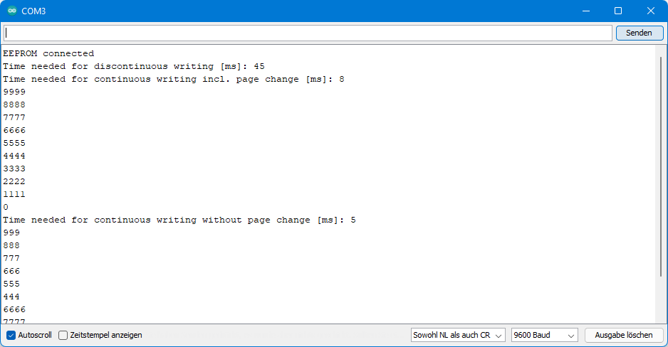
Here is the output:
Interpretation
The sketch contains four writing sequences. Since I choose the start address 125 in the first two writing sequences, there will definitely be a page change. For the third write sequence (start at address 0) there is no page change, unless you use an EEPROM with a page size of 16 bytes. The result:
- 45 milliseconds for: 10 x put() + 2 write cycle times
- 8 milliseconds for: 10 x continuousPut() + 2 write cycle times
- 4 milliseconds for: 10 x continuousPut() + 1 write cycle time
The last write sequence only shows how to use the hold pin.
Sleep mode and write protection
In the following sketch, I’d like to show you how to put the EEPROM to sleep and how to write-protect its memory or status register.
deepPowerDown()initiates the deep sleep of the SPI EEPROM.- The sketch shows that the EEPROM cannot be read in deep sleep.
powerUpAndReadID()wakes up the EEPROM and provides its ID.writeProtect(parameter)enables write protection for the EEPROM.- You can protect it completely, only the upper half of the address space or the upper quarter.
- The parameter
PROTECT_NONEdisables the write protection. - Setting the WP-pin to LOW alone does not enable write protection. In addition, the WPEN bit (Write Protect Enable Bit) must be set in the status register.
protectStatusRegister(true/false);enables read-only protection for the status register, but this only applies to the WPEN bit and the bits for setting the address space to be protected.
It’s a bit confusing to understand what protectStatusRegister() exactly does it. I hope the following sketch makes it a bit clearer.
#include <SPI.h>
#include <EEPROM_SPI_WE.h>
const int csPin = 10; // Chip select pin
const int wpPin = 9;  // Write protect pin (needed for this sketch)

/* There are different options to create your EEPROM_SPI_WE object:
 * EEPROM_SPI_WE myEEP = EEPROM_SPI_WE(csPin, wpPin, spiClockSpeed); // e.g. uint32t spiClockSpeed = 4000000
 * EEPROM_SPI_WE myEEP = EEPROM_SPI_WE(csPin, wpPin);
 * EEPROM_SPI_WE myEEP = EEPROM_SPI_WE(csPin);
 * EEPROM_SPI_WE myEEP = EEPROM_SPI_WE(&SPI, csPin, wpPin, spiClockSpeed);
 * EEPROM_SPI_WE myEEP = EEPROM_SPI_WE(&SPI, csPin, wpPin);
 * EEPROM_SPI_WE myEEP = EEPROM_SPI_WE(&SPI, csPin);
 * If you don't define the wpPin and you connect it to GND or VCC,
 * then protectStatusRegister() is the only function that won't work.
 * Passing the SPI object allows you, for example, to use both SPI
 * interfaces on the ESP32.
 */
  EEPROM_SPI_WE myEEP = EEPROM_SPI_WE(csPin, wpPin);

void setup(){
  Serial.begin(9600);
  if(myEEP.init()){
    Serial.println("EEPROM connected");
  }
  else{
    Serial.println("EEPROM does not respond");
    while(1);
  }
   /* You can change the SPI clock speed also after you have created your
   * object. The default is 8 MHz. Check the data sheet which clock speed is
   * allowed. The frequency limit migh also depend on the voltage.
   */
  //myEEP.setSPIClockSpeed(4000000); // use AFTER init()!

  /* Select the page size of your EEPROM.
   * Choose EEPROM_PAGE_SIZE_xxx,
   * with xxx = 16, 32, 64, 128 or 256
   */
  myEEP.setPageSize(EEPROM_PAGE_SIZE_128);

  /* Select the memory size of your EEPROM. This is important in case you use
   * EEPROMs > 512 kBit or in case you want to erase a complete small EEPROM
   * (typ. < 8 kBits). You can choose from:
   * EEPROM_KBITS_2 = 256 bytes,
   * EEPROM_KBITS_4 = 512 bytes,
   * EEPROM_KBITS_8 = 1024 bytes,
   * EEPROM_KBITS_16 = 2028 bytes,
   * EEPROM_KBITS_32 = 4096 bytes,
   * EEPROM_KBITS_64 = 8192 bytes,
   * EEPROM_KBITS_128 = 16384 bytes,
   * EEPROM_KBITS_256 = 32768 bytes,
   * EEPROM_KBITS_512 = 65536 bytes,
   * EEPROM_KBITS_1024 = 131072 bytes,
   * EEPROM_KBITS_2048 = 262144 bytes,
   * EEPROM_KBITS_4096 = 524288 bytes,
   */
  myEEP.setMemorySize(EEPROM_KBITS_512);

  int testInt = 42;
  myEEP.put(50, testInt);
  Serial.print("testInt: ");
  Serial.println(testInt);
  Serial.println("Going in deep power down mode...");
  myEEP.deepPowerDown();
  Serial.println("Trying to read testInt... ");
  myEEP.get(50, testInt);
  Serial.print("testInt: ");
  Serial.println(testInt);
  Serial.println("Releasing from deep power down  mode...");
  byte id = myEEP.powerUpAndReadID();
  Serial.print("testInt: ");
  myEEP.get(50, testInt);
  Serial.println(testInt);
  Serial.print("Device ID: 0x");
  Serial.println(id, HEX);
  Serial.println("");

/* You can write protect the device. The following options are available:
 * PROTECT_ALL              Complete write protection;
 * PROTECT_UPPER_QUARTER    Protect the upper quarter;
 * PROTECT_UPPER_HALF       Protect the upper half;
 * PROTECT_NONE             No write protection
 */
  myEEP.writeProtect(PROTECT_ALL);
  Serial.println("Protecting Device, trying to overwrite testInt...");
  myEEP.put(50, 4321);
  myEEP.writeProtect(PROTECT_NONE);
  Serial.print("testInt: ");
  myEEP.get(50, testInt);
  Serial.println(testInt);
  Serial.println("Protection removed, trying to overwrite testInt again...");
  myEEP.put(50, 4321);
  myEEP.get(50, testInt);
  Serial.print("testInt: ");
  Serial.println(testInt);
  Serial.println("");

  Serial.println("Protecting status register...");
  myEEP.protectStatusRegister(true);  //protects the non-volatile bits of status register
  Serial.println("Trying to protect device...");
  myEEP.writeProtect(PROTECT_ALL);
  Serial.println("Now overwriting testInt...");
  myEEP.put(50, 1234);
  myEEP.get(50, testInt);
  Serial.print("testInt: ");
  Serial.println(testInt);
  Serial.println("Status register protection prevented changing the device protection!");
  myEEP.protectStatusRegister(false);
}

void loop(){}
Here is a screenshot of the serial monitor:
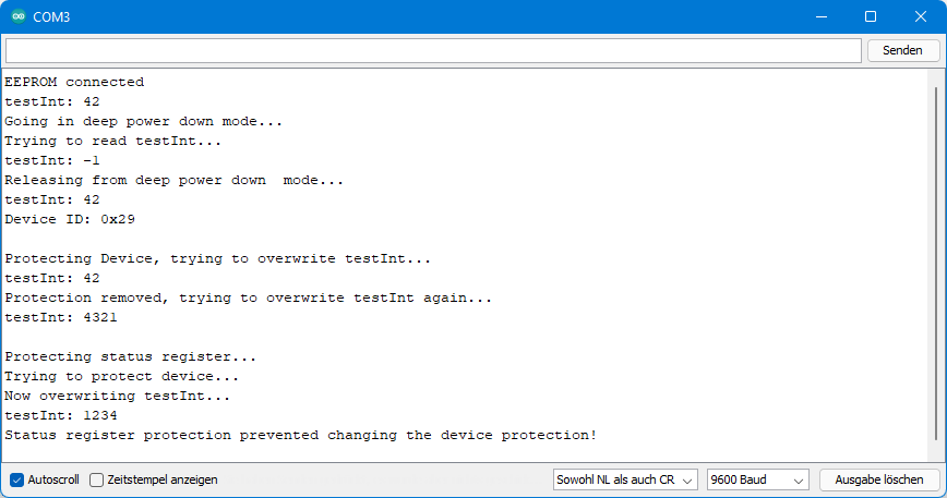
Despite calling myEEP.writeProtect(PROTECT_ALL), testInt can be overwritten at the end of the sketch because the status register was previously write-protected.
Erase functions
The larger SPI EEPROMs have erase functions. If in doubt, check the data sheet to see if this applies to your EEPROM – or try out the next sketch.
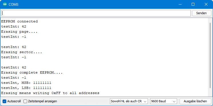
erasePage(address)deletes the page in which “address” is located. Which address you specify within the page does not matter.eraseSector(address)deletes the sector where the address is located. For example, the 25LC512 has 4 sectors.eraseCompleteEEPROM()does what the name suggests: the entire EEPROM is deleted.
What does “delete” actually mean? There is always a certain value at a specific address. That is why the term is somewhat misleading. For the functions described here, 255 (0xFF) is written to each memory address to be erased. If you try to read an integer value from a deleted memory area, it returns 0xFFFF = -1.
#include <SPI.h>
#include <EEPROM_SPI_WE.h>
const int csPin = 10; // Chip select pin
const int wpPin = 9;  // Write protect pin (optional)

/* There are different options to create your EEPROM_SPI_WE object:
 * EEPROM_SPI_WE myEEP = EEPROM_SPI_WE(csPin, wpPin, spiClockSpeed); // e.g. uint32t spiClockSpeed = 4000000
 * EEPROM_SPI_WE myEEP = EEPROM_SPI_WE(csPin, wpPin);
 * EEPROM_SPI_WE myEEP = EEPROM_SPI_WE(csPin);
 * EEPROM_SPI_WE myEEP = EEPROM_SPI_WE(&SPI, csPin, wpPin, spiClockSpeed);
 * EEPROM_SPI_WE myEEP = EEPROM_SPI_WE(&SPI, csPin, wpPin);
 * EEPROM_SPI_WE myEEP = EEPROM_SPI_WE(&SPI, csPin);
 * If you don't define the wpPin and you connect it to GND or VCC,
 * then protectStatusRegister() is the only function that won't work.
 * Passing the SPI object allows you, for example, to use both SPI
 * interfaces on the ESP32.
 */
  EEPROM_SPI_WE myEEP = EEPROM_SPI_WE(csPin, wpPin);

void setup(){
  Serial.begin(9600);
  if(myEEP.init()){
    Serial.println("EEPROM connected");
  }
  else{
    Serial.println("EEPROM does not respond");
    while(1);
  }
   /* You can change the SPI clock speed also after you have created your
   * object. The default is 8 MHz. Check the data sheet which clock speed is
   * allowed. The frequency limit migh also depend on the voltage.
   */
  //myEEP.setSPIClockSpeed(4000000); // use AFTER init()!

  /* Select the page size of your EEPROM.
   * Choose EEPROM_PAGE_SIZE_xxx,
   * with xxx = 16, 32, 64, 128 or 256
   */
  myEEP.setPageSize(EEPROM_PAGE_SIZE_128);

  /* Select the memory size of your EEPROM. This is important in case you use
   * EEPROMs > 512 kBit or in case you want to erase a complete small EEPROM
   * (typ. < 8 kBits). You can choose from:
   * EEPROM_KBITS_2 = 256 bytes,
   * EEPROM_KBITS_4 = 512 bytes,
   * EEPROM_KBITS_8 = 1024 bytes,
   * EEPROM_KBITS_16 = 2028 bytes,
   * EEPROM_KBITS_32 = 4096 bytes,
   * EEPROM_KBITS_64 = 8192 bytes,
   * EEPROM_KBITS_128 = 16384 bytes,
   * EEPROM_KBITS_256 = 32768 bytes,
   * EEPROM_KBITS_512 = 65536 bytes,
   * EEPROM_KBITS_1024 = 131072 bytes,
   * EEPROM_KBITS_2048 = 262144 bytes,
   * EEPROM_KBITS_4096 = 524288 bytes,
   */
  //myEEP.setMemorySize(EEPROM_KBITS_1024);

  int testInt = 42;
  myEEP.put(10, testInt);
  myEEP.get(10, testInt);
  Serial.print("testInt: ");
  Serial.println(testInt);
  Serial.println("Erasing page....");
  myEEP.erasePage(3);  // choose any address within the page you want to erase
  myEEP.get(10, testInt);
  Serial.print("testInt: ");
  Serial.println(testInt);
  Serial.println("");

  testInt = 42;
  myEEP.put(10, testInt);
  myEEP.get(10, testInt);
  Serial.print("testInt: ");
  Serial.println(testInt);
  Serial.println("Erasing sector....");
  myEEP.eraseSector(7); // choose any address within the sector you want to erase
  myEEP.get(10, testInt);
  Serial.print("testInt: ");
  Serial.println(testInt);
  Serial.println("");

  testInt = 42;
  myEEP.put(10, testInt);
  myEEP.get(10, testInt);
  Serial.print("testInt: ");
  Serial.println(testInt);
  Serial.println("Erasing complete EEPROM....");
  myEEP.eraseCompleteEEPROM();
  myEEP.get(10, testInt);
  Serial.print("testInt: ");
  Serial.println(testInt);

  Serial.print("testInt, MSB: ");
  Serial.println(myEEP.read(10), BIN);
  Serial.print("testInt, LSB: ");
  Serial.println(myEEP.read(11), BIN);
  Serial.println("Erasing means writing 0xFF to all addresses");
}

void loop(){}
Here is the output:
Reference – SPI EEPROMs internal
This section is intended for those who are particularly interested but do not feel like reading the data sheet.
Instruction Set
The SPI EEPROMs have a rather limited set of functions (instructions):
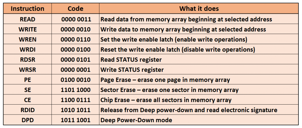
Not every EEPROM has implemented all of these features. This is especially true for the erase functions.
Status register
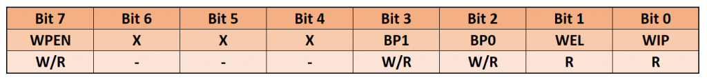
The status register is the only register in the SPI EEPROM. The WPEN bit (Write Protection Enable) and the two BP bits (Block Protection) are non-volatile, meaning that their values are retained even after the power supply is disconnected. However, I have configured my library so that all bits are set to zero on a reboot.
If you want to write to the EEPROM, you have to set the WEL bit (Write Enable Latch). It is deleted following a successful write or delete operation, a restart, or via the WRDI instruction.
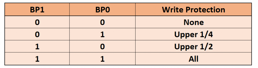
The BP bits have the following effect (in combination with WPEN):
write protection
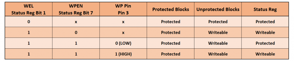
The table above describes the effect of the WEL bit, WPEN bit, and WP pin on read-only protection for the EEPROM and its status register.
Acknowledgement
I copied the variable handling of the put() and get() function from the great Sparkfun library SparkFun_External_EEPROM_Arduino_Library for I2C EEPROMs. I have introduced this library in my last post.
Thanks for the library. I’ve used it with an ESP32 and a W25C128. I came accross an error. When you send the address for EEproms bigger than 64k but smaller than 1024K you also have to send a third address byte.
To change this, change EEPROM_KBITS_512 to EEPROM_KBITS_64.
Further a remark if you put the while(isBusy()){} at the start you can do a lot of work while the EEprom is writing his data. Only when you want to read or write you have to wait until finished with the internal processes.
Hi and thanks for your comment. EEPROMs bigger than 64 kByte need a third bit, but EEPROM_KBITS_512 is in kbits and 512 kbit are 64 kByte which means 64k addresses = 2 Byte. So, I still think this is correct. Or have I overlooked something? It’s quite some that I looked into this library.
But I found another issue: It seems I have nowhere used or explained the function setMemorySize(). This is of course important.
For the other recommendation, I need to take some time to check.
Thank you for your library and examples. Couldn’t find much else anywhere else.
Thank you!!
Great library, it helped me a lot
Thank you!
I using your EEProm library and am having trouble trying to use a char array; You example has int array; How would I use your code for a char array?
Here’s an example:
unsigned int address = 30;
char arrayToWrite1[] = “Arduino”;
Serial.println(sizeof(arrayToWrite1));
myEEP.put(address, arrayToWrite1);
char arrayToRead1[8] = “”;
myEEP.get(30, arrayToRead1);
Serial.print(arrayToRead1);
address += sizeof(arrayToRead1);
char arrayToWrite2[] = ” is great”;
myEEP.put(address, arrayToWrite2);
char arrayToRead2[10] = “”;
myEEP.get(address, arrayToRead2);
Serial.println(arrayToRead2);
Since the char arrays have a varying length, you have to determine the length with sizeof() and calculate the new address. Be aware that char arrays are always terminated with the invisible null character ‘\0’. That’s why sizeof() for “Arduino” returns 8 and not 7. If you read an EEPROM with stored char arrays and you don’t know the lengths of the char arrays then you can read each char array character by character until you read the null character.
The handling of char arrays and strings can be a bit tricky. I discussed this in my post about internal EEPROMS:
https://wolles-elektronikkiste.de/en/eeprom-part-1-avr-internal-eeproms#character-arrays-und-strings-auf-dem-eeprom-speichern