About this Post
In my last post, I discussed the internal EEPROM of AVR microcontrollers and AVR-based Arduino boards. In this post, I will now focus on external, I²C-controlled EEPROMs. With suitable libraries, such as the one from Sparkfun, you can write and read the EEPROMs very conveniently. For a better understanding, however, it is also worthwhile to learn how this works without a library. And that is exactly what this post is about.
The article is structured as follows:
- Introduction
- Pinout and connection to the microcontroller
- Addressing scheme
- Writing to and reading from the EEPROM
- Writing larger data sets
- Page Write
- Sparkfun Library
I will cover external SPI-based EEPROMs in a separate post. They differ from I²C-based EEPROMs in such a way that I couldn’t cover both in a single article.
Introduction
What is an EEPROM?
The abbreviation EEPROM stands for “Electrically Erasable Programmable Read Only Memory”. This somewhat contradictory name has evolved historically. I discussed this in my last post. In short, an EEPROM serves as a memory for data that should not be lost even after the power supply has been switched off.
What are the characteristics of EEPROMs?
One of the advantages of EEPROMs is their compact design. In addition, the data on an EEPROM is stored securely for a comparatively long time. In some cases, manufacturers guarantee data retention of more than 200 years. I will check this in 200 years and complain if necessary ;-).
A disadvantage, however, is the comparatively slow write speed of the EEPROMs. It is in the range of milliseconds for a single byte. Through “Page Writing”, the models discussed here increase their effective write speed considerably compared to the internal EEPROMs. However, they are still much slower than flash memory.
An EEPROM has a limited lifetime in terms of the number of write cycles. However, this disadvantage is of limited relevance, as the specified limit set is usually higher than one million. If the same memory cell were overwritten every second, its lifetime would be reached after ~11.5 days. If you overwrite it every 5 minutes, the lifetime would be exceeded after almost 20 years.
The EEPROMs I will discuss
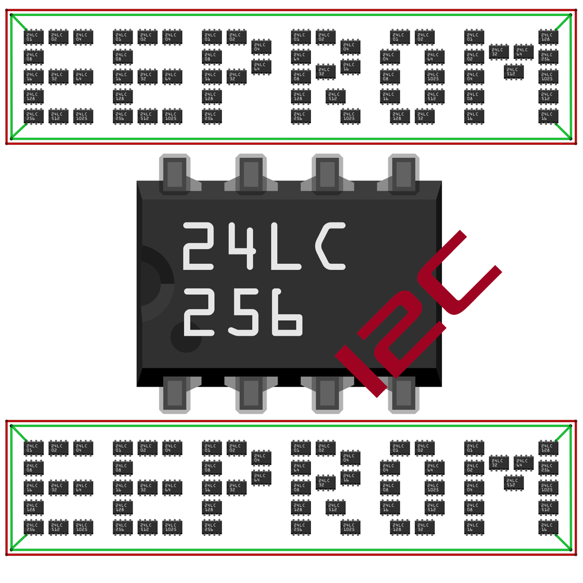
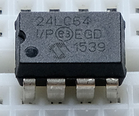
In this article, I will focus on EEPROMs of the 24 series. These EEPROMs are labeled according to the scheme “24xxyy”.
The “xx” part encodes different voltage ranges and transmission speeds. Often you will find “LC”, “C” and “A” types. The “yy” usually indicates the storage capacity in kilobits. For example, at the bottom left you can see a “24LC64,” which has a capacity of 64 kbit = 8 kilobytes (abbreviated as kB or kByte). An exception is the 24LC1025, which has a storage capacity of 1024 kbit.
You control the 24-series via I²C. There are also other series. The 25 series, for example, is controlled by SPI, the 11, 21 and 28 series communicate via one-wire techniques.
Further abbreviations define design types (PDIP, SIOC, etc), temperature ranges and others.
Power
The EEPROMs are quite undemanding as far as their power requirements are concerned. While writing, they usually consume 0.1 -1.0 milliamps. When reading, the value is even lower. In standby, the maximum current is a few microamps.
Pinout and connection to the microcontroller
Pinout of the 24 EEPROM series
The pinout of the EEPROMs of the 24 series usually looks like this:
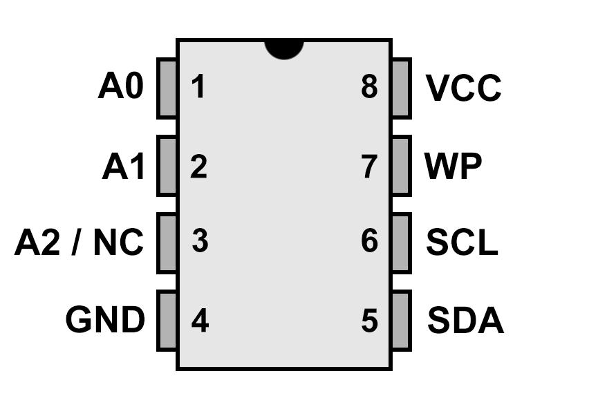
- A0 / A1 / (A2): Address pins, 4 to 8 addresses can usually be set.
- VCC / GND: Power supply, for example 2.5 – 5.5 Volt for the 24LCxx series (check the data sheet!).
- WP: Write Protection;
- Inactive when connected to GND.
- Active when connected to VCC.
- SDA / SCL: I²C connections, max. 400 kHz for the 24LCxx series (check the data sheet!).
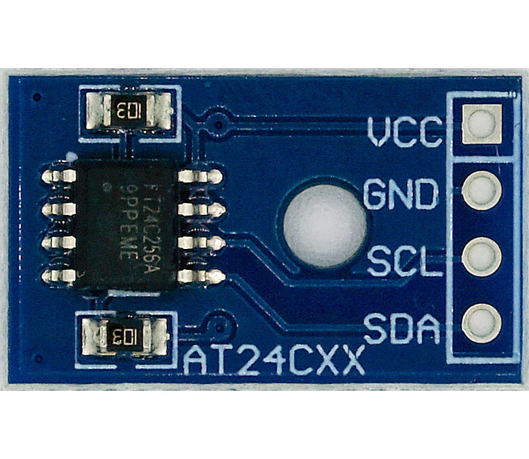
Connection to an Arduino Nano
Example circuit of a 24LC256 on an Arduino Nano:
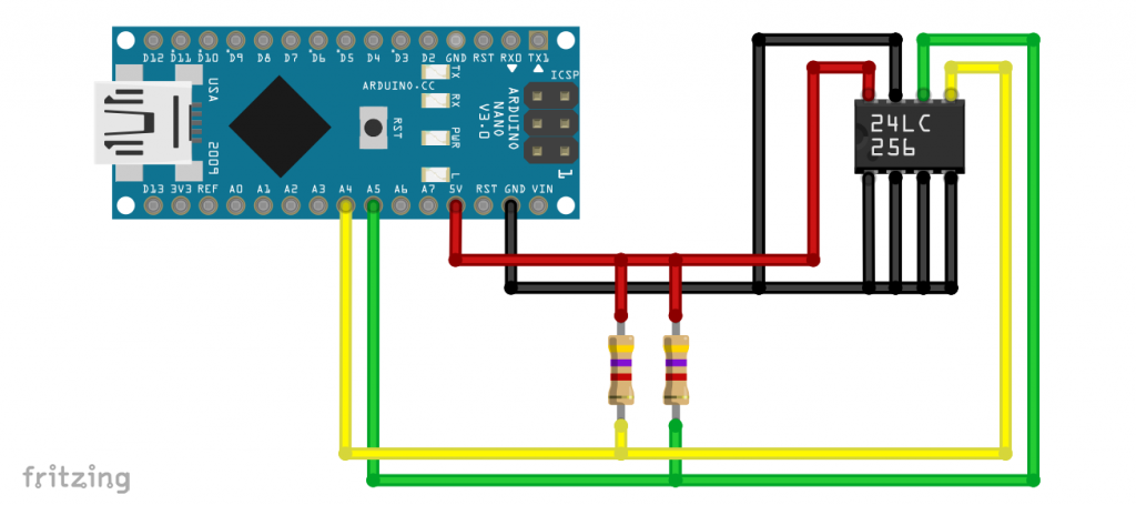
Often you can do without the pull-up resistors. Just try it.
Addressing scheme
The addressing of LC24xx EEPROMs follows different rules depending on their size. However, the base address 0x50 (=0b1010000) is the same for all of them.
For EEPROMs ranging in size from 32 to 512 kbit, a total of eight different I²C addresses can be set using the lower three bits, i.e., 0x50 to 0x57. The memory addresses are coded by 2 bytes.

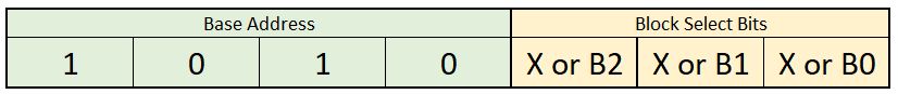
The small EEPROMs ranging in size from 1 to 16 kB are organized in memory blocks. The 24L01 has a block size of 128 bytes. The 24LC02 has a block size of 256 bytes. The lower 3 bits of the I²C address have no significance for these devices, meaning you can only use one of these EEPROMs per I²C interface. The memory addresses “fit” into a single byte.
The 24LC04 has two memory blocks, each with a capacity of 256 bytes. The blocks are addressed using different I²C addresses. This is controlled by bit B0 (see below). As a result, the memory address within the block can still be written to using a single byte.
The 24LC08 works the same way, except that it has 4 blocks addressed via B0 and B1. The 24LC16 has 8 blocks addressed via B0, B1, and B2.
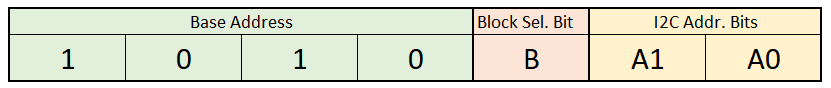
With the 24LC1025, the addresses no longer fit into 2 bytes. This EEPROM therefore has two blocks, each with a capacity of 64 kB. As with smaller EEPROMs, the block is selected via the I²C address. However, this is done here using bit 3. Using the lower two bits, you can address four different I²C addresses.
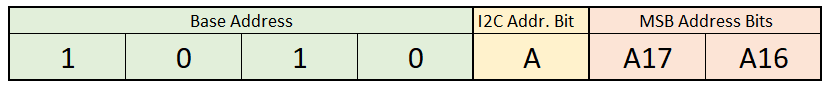
Finally, there are 2-Mbit EEPROMs such as the AT24CM02. Memory addressing requires 18 bits (bits 0–17). The most significant memory address bits are part of the lower two bits of the I²C address. Bit 3 of the I²C address allows you to address two of these EEPROMs. The AT24CM01 essentially follows the same scheme, except that it only uses the MSB address bit A16 and has 2 I²C address bits.
Writing to and reading from the EEPROM
Medium-sized EEPROMs – 24LC32 to 24LC512
In this first, simple example, we write four byte values to the EEPROM and then read them back. You initiate the writing process with Wire.beginTransmission().
In the next step, you use Wire.write() to pass the memory address at which you want to store the value. For memory capacities between 32 and 512 kbit (equivalent to 4 to 64 kbyte), memory addresses are encoded using two bytes. To do this, divide the address into its MSB (Most Significant Byte) and LSB (Least Significant Byte) and transmit them sequentially.
You complete the write operation with Wire.endTransmission(). However, the EEPROM still needs some time to finish the write cycle. You cannot write any more data to the EEPROM until this process is completed. The “write cycle time” is listed in your EEPROM’s datasheet. It is typically 5 milliseconds.
When writing to the EEPROM, you need to keep track of the memory address. There is no function that would warn you that a memory location has already been written to. Strictly speaking, there is no distinction between written and unwritten memory cells. In any case, there is a value stored there. A cleared memory address is written with ones. If you read it as a byte, you get 0b11111111 = 0xFF = 255.
For reading, you use the Wire.requestFrom() function. You don’t have to add any waiting time between the read operations.
#include <Wire.h>
#define I2C_ADDRESS 0x50

void setup(){
  Wire.begin();
  Serial.begin(115200);

  uint16_t address = 0;
  uint8_t byteVal_1 = 42;
  uint8_t byteVal_2 = 123;
  uint8_t byteVal_3 = 99;
  uint8_t byteVal_4 = 222;

  eepromByteWrite(address,byteVal_1);
  address++;
  eepromByteWrite(address,byteVal_2);
  address++;
  eepromByteWrite(address,byteVal_3);
  address++;
  eepromByteWrite(address,byteVal_4);

  for(address=0; address<4; address++){
    Serial.print("Byte at address ");
    Serial.print(address);
    Serial.print(": ");
    Serial.println(eepromByteRead(address));
  }
}

void loop(){}

void eepromByteWrite(uint16_t addr, uint8_t byteToWrite){
  Wire.beginTransmission(I2C_ADDRESS);
  Wire.write((uint8_t)(addr >> 8));
  Wire.write((uint8_t)(addr & 0xFF));
  Wire.write(byteToWrite);
  Wire.endTransmission();
  delay(5); // important!
}

uint8_t eepromByteRead(uint16_t addr){
  uint8_t byteToRead;

  Wire.beginTransmission(I2C_ADDRESS);
  Wire.write((uint8_t)(addr >> 8));
  Wire.write((uint8_t)(addr & 0xFF));
  Wire.endTransmission();
  Wire.requestFrom(I2C_ADDRESS, 1);
  byteToRead = Wire.read();

  return byteToRead;
}
Here’s what the output looks like:

Kleine EEPROMs – 24LC01 bis 24LC16
As explained above, memory addresses in small EEPROMs are represented by a single byte. As this is no longer sufficient from the 24LC04 (512 memory addresses) onwards, the memory is divided into blocks of 256 bytes each, which can be accessed via different I²C addresses. In the following sketch, the functions `eepromByteWrite()` and `eepromByteRead()` handle the splitting into I²C addresses and block addresses.
To demonstrate that block allocation works, the sketch writes the four bytes to memory addresses 254 to 257.
#include <Wire.h>
#define I2C_ADDRESS 0x50

void setup(){
  Wire.begin();
  Serial.begin(115200);

  /* choose smaller start address for 24lc02 or 24lc01 */
  const uint16_t startAddress = 254;
  uint16_t address = startAddress;
  uint8_t byteVal_1 = 42;
  uint8_t byteVal_2 = 123;
  uint8_t byteVal_3 = 99;
  uint8_t byteVal_4 = 222;

  eepromByteWrite(address,byteVal_1);
  address++;
  eepromByteWrite(address,byteVal_2);
  address++;
  eepromByteWrite(address,byteVal_3);
  address++;
  eepromByteWrite(address,byteVal_4);

  for(address=startAddress; address<(startAddress+4); address++){
    Serial.print("Byte at address ");
    Serial.print(address);
    Serial.print(": ");
    Serial.println(eepromByteRead(address));
  }
}

void loop(){}

void eepromByteWrite(uint16_t addr, uint8_t byteToWrite){
  uint8_t i2cAddr = I2C_ADDRESS + addr/256;
  uint8_t blockAddr = addr%256;

  Wire.beginTransmission(i2cAddr);
  Wire.write(blockAddr);
  Wire.write(byteToWrite);
  Wire.endTransmission();
  delay(5); // important!
}

uint8_t eepromByteRead(uint16_t addr){
  uint8_t byteToRead;
  uint8_t i2cAddr = I2C_ADDRESS + addr/256;
  uint8_t blockAddr = addr%256;

  Wire.beginTransmission(i2cAddr);
  Wire.write(blockAddr);
  Wire.endTransmission();
  Wire.requestFrom(I2C_ADDRESS, 1);
  byteToRead = Wire.read();

  return byteToRead;
}
This is the output:
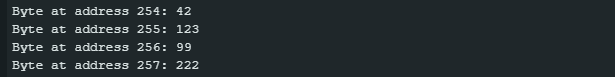
Surprisingly, the sketch also works on a 24LC01 with the same output. The solution to the puzzle: The EEPROM uses only the lower 7 bits of the memory address. Accordingly, byteVal_1 and byteVal_2 are written to addresses 126 and 127, while byteVal_3 and byteVal_4 end up at addresses 0 and 1. And why does this work for byteVal_3 and byteVal_4, even though the I²C address changes to 0x51? Even though the lower 3 bits of the I²C address don’t matter for this EEPROM, you’ll still get eight I²C addresses (0x50 to 0x57) with an I²C scanner. It “listens” to all these addresses but always writes to the same memory block. You can verify this by reading addresses 0 through 127.
Large EEPROMs – 24LC1025 (and AT24CM01/02)
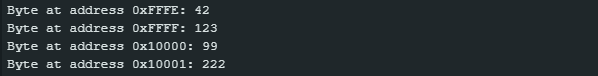
With the 24LC1025, the two bytes of memory addresses are not sufficient. For this reason, it operates with two blocks that have different I²C addresses. Based on the addressing scheme, these are 0x50 and 0x54. The following sketch writes two bytes to addresses 0xFFFE and 0xFFFF (65534 and 65535), which are the last two addresses of the first memory block. The other bytes are written to addresses 0x10000 and 0x10001, which are addresses 0 and 1 of the second block.
#include <Wire.h>
#define I2C_ADDRESS_1 0x50
#define I2C_ADDRESS_2 0x54

void setup(){
  Wire.begin();
  Serial.begin(115200);

  uint32_t address = 0xFFFE;
  uint8_t byteVal_1 = 42;
  uint8_t byteVal_2 = 123;
  uint8_t byteVal_3 = 99;
  uint8_t byteVal_4 = 222;

  eepromByteWrite(address,byteVal_1);
  address++;
  eepromByteWrite(address,byteVal_2);
  address++;
  eepromByteWrite(address,byteVal_3);
  address++;
  eepromByteWrite(address,byteVal_4);

  for(address = 0xFFFE; address < 0x10002; address++){
    Serial.print("Byte at address 0x");
    Serial.print(address, HEX);
    Serial.print(": ");
    Serial.println(eepromByteRead(address));
  }
}

void loop(){}

void eepromByteWrite(uint32_t addr, uint8_t byteToWrite){
  uint8_t i2cAddr = I2C_ADDRESS_1;

  if (addr > 0xFFFF){
    i2cAddr = I2C_ADDRESS_2;
  }

  Wire.beginTransmission(i2cAddr);
  Wire.write((uint8_t)(addr >> 8));
  Wire.write((uint8_t)(addr & 0xFF));
  Wire.write(byteToWrite);
  Wire.endTransmission();
  delay(5); // important!
}

uint8_t eepromByteRead(uint32_t addr){
  uint8_t byteToRead;
  uint8_t i2cAddr = I2C_ADDRESS_1;

  if (addr > 0xFFFF){
    i2cAddr = I2C_ADDRESS_2;
  }

  Wire.beginTransmission(i2cAddr);
  Wire.write((uint8_t)(addr >> 8));
  Wire.write((uint8_t)(addr & 0xFF));
  Wire.endTransmission();
  Wire.requestFrom(i2cAddr, 1);
  byteToRead = Wire.read();

  return byteToRead;
}
The output is:
For the AT24CM01 and AT24CM02, you need to modify the sketch. I didn’t feel like doing it anymore.
Writing larger data sets to the EEPROM
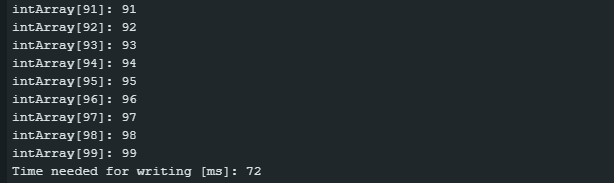
In the next example, we first create an array of one hundred integers. The value of the i-th element of the array is 10 · i (arbitrarily chosen). We write the array to the EEPROM, read it from there, and display it on the serial monitor.
Please note that I am writing this and the following examples exclusively for medium-sized EEPROMs. However, you should have no trouble modifying them if necessary.
Here is the sketch:
#include <Wire.h>
#define I2C_ADDRESS 0x50

void setup(){
  Wire.begin();
  //Wire.setClock(400000);
  Serial.begin(115200);
  uint16_t address = 0;
  uint32_t writeStart = 0;
  uint32_t writeDuration = 0;

  uint16_t arraySize = 100;
  int16_t intArray[arraySize];

  for(uint16_t i=0; i<arraySize; i++){
    intArray[i] = i*10;
  }
  writeStart = millis();
  writeIntArrayToEEPROM(address, intArray, arraySize);
  writeDuration = millis() - writeStart;

  address = 0;
  for(uint16_t i=0; i<arraySize; i++){
    Serial.print("intArray[");
    Serial.print(i);
    Serial.print("]: ");
    Serial.println(readIntFromEEPROM(address + 2*i));
  }
  Serial.print("Time needed for writing [ms]: ");
  Serial.println(writeDuration);
}

void loop(){}

void writeIntArrayToEEPROM(uint16_t addr, int16_t *iArr, uint16_t arrSize){
  for(uint16_t i = 0; i<arrSize; i++){
    Wire.beginTransmission(I2C_ADDRESS);
    Wire.write((uint8_t)((2*i + addr) >> 8));
    Wire.write((uint8_t)((2*i + addr) & 0xFF));
    Wire.write((uint8_t)(iArr[i] >> 8));
    Wire.write((uint8_t)(iArr[i]) & 0xFF);
    Wire.endTransmission();
    delay(5);
//    while(isBusy()){   // alternativ to delay(5).
//      delayMicroseconds(50);
//    }
  }
}

int16_t readIntFromEEPROM(uint16_t addr){
  int16_t intToRead;
  uint8_t msByte;
  uint8_t lsByte;
  Wire.beginTransmission(I2C_ADDRESS);
  Wire.write((uint8_t)(addr >> 8));
  Wire.write((uint8_t)(addr & 0xFF));
  Wire.endTransmission();
  Wire.requestFrom(I2C_ADDRESS, 2);
  msByte = Wire.read();
  lsByte = Wire.read();
  intToRead = msByte << 8 | lsByte;
  return intToRead;
}

bool isBusy(){
  Wire.beginTransmission(I2C_ADDRESS);
  return Wire.endTransmission();
}
Just a few explanations:
- The array is passed to the write function
writeIntArrayToEEPROM()as a pointer. I discussed this in my last post. - An integer is two bytes (at least on an Arduino). Therefore, not only the address, but also the value to be written must be split into MSB and LSB.
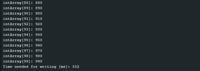
Writing the array took 552 milliseconds. 500 milliseconds of this time is “write cycle time”. If your EEPROM supports fast I²C, you can reduce the remaining 52 milliseconds by uncommenting line 6, Wire.setClock(400000). This will increase the I²C frequency from 100 to 400 kHz. At 400 kHz I was able to reduce the write process to 519 milliseconds.
The data sheet specifies the “write cycle Ttme” to be 5 milliseconds. In reality it’s shorter. As long as the EEPROM is busy writing, it cannot be accessed via I²C. This means that it will acknowledge during a write cycle. This property is used by the function isBusy() to check if the EEPROM is available.
Comment line 43, delay(5), and uncomment the following three lines. With this measure and the switch to 400 kHz, the time required to write the array dropped to 380 milliseconds. The real “write cycle time” is therefore about 3.5 milliseconds.
EEPROM Page Write
As you have just seen, it is possible to write several bytes to the EEPROM “in one go” (Page Write), i.e. without intermediate Wire.endTransmission() and delay(). Otherwise, writing to the integer array would have taken at least 1000 milliseconds.
This works because the EEPROM is segmented into memory sections (Pages) and has a buffer for these sections. The data to be written is quickly transferred to the buffer. And from there the data is written to the memory. The advantage is that writing the entire buffer to the memory takes no longer than the write cycle time. The page size can be found in the data sheet. For the 24LC64 the page size is 32 bytes, for a 24LC256 it is 64 bytes.
The pages start and end at fixed memory addresses. Page writing beyond the end of a page does not work.
Limitation by the Wire.write() buffer
For page writing, there is still a limiting factor related to the Arduino. And that’s the buffer for Wire.write(). You can see how this works with the following sketch (provided you’re using a board with a 32-byte buffer and an EEPROM with a page size of at least 32):
#include <Wire.h>
#define I2C_ADDRESS 0x50

/* choose a greater number if the i2c buffer is bigger, e.g. a number
   greater than 128 for an ESP32 board */
uint8_t numOfValues = 64;

void setup(){
  Wire.begin();
  Serial.begin(115200);
  uint16_t address = 0;

  for(uint16_t i=address; i<numOfValues; i++){
    eepromByteWrite(i,(uint8_t)i);
  }

  uint8_t byteArray[numOfValues];
  for(uint8_t i=0; i<numOfValues; i++){
    byteArray[i] = i*2;
  }
  eepromBytePageWrite(address, byteArray, sizeof(byteArray));

  address = 0;
  for(uint16_t i=address; i<sizeof(byteArray); i++){
    Serial.print("byteArray[");
    Serial.print(i);
    Serial.print("]: ");
    Serial.println(readEEPROM(i));
  }
}
void loop(){}

void eepromByteWrite(uint16_t addr, uint8_t byteToWrite){
  Wire.beginTransmission(I2C_ADDRESS);
  Wire.write((uint8_t)(addr >> 8));
  Wire.write((uint8_t)(addr & 0xFF));
  Wire.write(byteToWrite);
  Wire.endTransmission();
  delay(5);
}

void eepromBytePageWrite(uint16_t addr, uint8_t *byteArrayToWrite, uint8_t sizeOfArray){
  Wire.beginTransmission(I2C_ADDRESS);
  Wire.write((uint8_t)(addr >> 8));
  Wire.write((uint8_t)(addr & 0xFF));
  for(uint16_t i=addr; i<sizeOfArray; i++){
    Wire.write(byteArrayToWrite[i]);
  }
  Wire.endTransmission();
  delay(5);
}

uint8_t readEEPROM(uint16_t addr){
  byte byteToRead;
  Wire.beginTransmission(I2C_ADDRESS);
  Wire.write((uint8_t)(addr >> 8));
  Wire.write((uint8_t)(addr & 0xFF));
  Wire.endTransmission();
  Wire.requestFrom(I2C_ADDRESS, 1);
  byteToRead = Wire.read();
  return byteToRead;
}
The sketch writes values to the first 64 EEPROM memory addresses, namely the address itself. The values are written individually and with a 5 millisecond pause. With this, we have a defined initial state.
Then the sketch writes (or at least tries to write) 64 new values (address multiplied by 2) to the EEPROM. This time it uses the page write method. Here is the unexpected result:
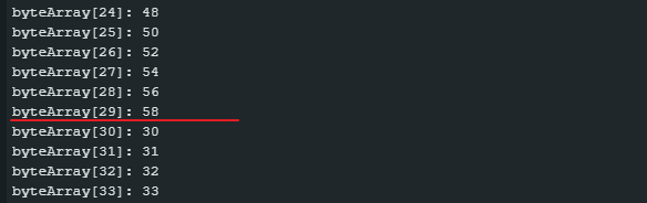
The first 30 values (0–29) have been replaced by the page-write method; after that, we encounter the old values. The reason is as follows: For successive Wire.write() commands (i.e. without intermediate Wire.endTransmission()), the data to be written is written to a buffer that is limited to 32 bytes. This happens on the Arduino side, and it has nothing to do with the EEPROM. The transmission of the address requires 2 bytes, so there are still 30 bytes left for the data. All additional Wire.write() calls end up in Nirvana.
Correct page writing
In summary: when using the page-write method, there are three things to keep in mind:
- The page size,
- the “wire.write()” buffer and
- Data must not be written beyond the current page.
In the next example, we write an array of 100 integer values (= 200 bytes) to an EEPROM with a page size of 64 bytes using the page write method correctly. If we start at the address 0, then we have 64 bytes which we can write to the page. The limiting factor is the Wire.write() buffer. So we write to memory locations 0–29, then 30–59. After that, we need to be aware that the page ends at address 63, so we can only write 4 additional bytes. The same happens in the following two pages. Finally, we write the remaining 8 bytes to the last page. Schematically, it looks like this:

A sketch could look like this:
#include <Wire.h>
#define I2C_ADDRESS 0x50
#define PAGE_SIZE 64
#define WRITE_LIMIT 30

void setup(){
  Wire.begin();
  Serial.begin(115200);
  uint16_t address = 0;
  uint32_t writeStart = 0;
  uint32_t writeDuration = 0;

  uint16_t arraySize = 100;
  int intArray[arraySize];

  for(uint16_t i=0; i<arraySize; i++){
    intArray[i] = i;
  }
  writeStart = millis();
  writeIntArrayToEEPROM(address, intArray, arraySize);
  writeDuration = millis() - writeStart;

  address = 0;
  for(uint16_t i=0; i<arraySize; i++){
    Serial.print("intArray[");
    Serial.print(i);
    Serial.print("]: ");
    Serial.println(readIntFromEEPROM(address + 2*i));
  }
  Serial.print("Time needed for writing [ms]: ");
  Serial.println(writeDuration);
}

void loop(){}

void writeIntArrayToEEPROM(uint16_t addr, int *iArr, uint16_t arrSize){
  uint16_t noOfIntsStillToWrite = arrSize;
  uint16_t arrayIndex = 0;

  while((noOfIntsStillToWrite != 0)){
    uint16_t chunk = (WRITE_LIMIT / sizeof(uint16_t));  // max chunk in number of ints
    uint16_t positionInPage = (addr % PAGE_SIZE);  // current position in page
    uint16_t spaceLeftInPage = (PAGE_SIZE - positionInPage) / sizeof(uint16_t); // available storage space
    if(spaceLeftInPage < chunk){
      chunk = spaceLeftInPage;
    }
    if(noOfIntsStillToWrite < chunk){
      chunk = noOfIntsStillToWrite;
    }
    writeEEPROM(addr, iArr, chunk, arrayIndex);
    noOfIntsStillToWrite -= chunk;
    addr += (chunk * 2);
    arrayIndex += chunk;
  }
}

void writeEEPROM(uint16_t addr, int *iArr, uint16_t chunkSize, uint16_t arrIdx){
  Wire.beginTransmission(I2C_ADDRESS);
  Wire.write((uint8_t)(addr>>8));
  Wire.write((uint8_t)(addr&0xFF));

  for(uint16_t i=0; i<chunkSize; i++){
    Wire.write((uint8_t)(iArr[i+arrIdx]>>8));
    Wire.write((uint8_t)(iArr[i+arrIdx])&0xFF);
  }
  Wire.endTransmission();
  delay(5);
}

int16_t readIntFromEEPROM(uint16_t addr){
  int16_t intToRead;
  uint8_t msByte;
  uint8_t lsByte;
  Wire.beginTransmission(I2C_ADDRESS);
  Wire.write((uint8_t)(addr>>8));
  Wire.write((uint8_t)(addr&0xFF));
  Wire.endTransmission();
  Wire.requestFrom(I2C_ADDRESS, 2);
  msByte = Wire.read();
  lsByte = Wire.read();
  intToRead = (int16_t)(msByte<<8 | lsByte);
  return intToRead;
}
So you have to always calculate how many bytes you can write to the EEPROM in a single step. As expected, the speed gain through the page write method is considerable:
Again, you can further increase the speed by using the isBusy() function and by switching to 400 kHz. The latter, of course, only if the EEPROM masters it.
Sparkfun Library
You can make your life much easier by using a library. I tested the SparkFun_External_EEPROM_Arduino_Library. It is easy to use and quite comfortable. You can install the library via the library manager of the Arduino IDE or you can download it directly from GitHub (link). The functions get() and put() are similar to the corresponding functions from EEPROM.h for the internal EEPROMs of the AVR boards. The usage is practically the same.
If you want to write strings to the EEPROM or read them from it, use functions putString() and getString(), respectively. The rest should actually be self-explanatory. Here is an example sketch:
/*
  Read and write settings and calibration data to an external I2C EEPROM
  By: Nathan Seidle
  SparkFun Electronics
  Date: December 11th, 2019
  License: This code is public domain but you buy me a beer if you use this
  and we meet someday (Beerware license).
  Feel like supporting our work? Buy a board from SparkFun!
  https://www.sparkfun.com/products/18355

  This example demonstrates how to read and write various variables to memory.

  The I2C EEPROM should have all its ADR pins set to GND (0). This is default
  on the Qwiic board.

  Hardware Connections:
  Plug the SparkFun Qwiic EEPROM to an Uno, Artemis, or other Qwiic equipped board
  Load this sketch
  Open output window at 115200bps
*/

#include <Wire.h>

#include "SparkFun_External_EEPROM.h" // Click here to get the library: http://librarymanager/All#SparkFun_External_EEPROM
ExternalEEPROM myMem;

void setup()
{
  Serial.begin(115200);
  //delay(250); //Often needed for ESP based platforms
  Serial.println("Qwiic EEPROM example");

  Wire.begin();

  //We must set the memory specs. Pick your EEPROM From the list:

  // 24xx00 - 128 bit / 16 bytes - 1 address byte, 1 byte page
  // 24xx01 - 1024 bit / 128 bytes - 1 address byte, 8 byte page
  // 24xx02 - 2048 bit / 256 bytes - 1 address byte, 8 byte page
  // 24xx04 - 4096 bit / 512 bytes - 1 address byte, 16 byte page
  // 24xx08 - 8192 bit / 1024 bytes - 1 address byte, 16 byte page
  // 24xx16 - 16384 bit / 2048 bytes - 1 address byte, 16 byte page
  // 24xx32 - 32768 bit / 4096 bytes - 2 address bytes, 32 byte page
  // 24xx64 - 65536 bit / 8192 bytes - 2 address bytes, 32 byte page
  // 24xx128 - 131072 bit / 16384 bytes - 2 address bytes, 64 byte page
  // 24xx256 - 262144 bit / 32768 bytes - 2 address bytes, 64 byte page
  // 24xx512 - 524288 bit / 65536 bytes - 2 address bytes, 128 byte page
  // 24xx1025 - 1024000 bit / 128000 byte - 2 address byte, 128 byte page
  // 24xxM02 - 2097152 bit / 262144 byte - 2 address bytes, 256 byte page

  // Setting the memory type configures the memory size in bytes, the number of address bytes, and the page size in bytes.

  // Default to the Qwiic 24xx512 EEPROM: https://www.sparkfun.com/products/18355
  myMem.setMemoryType(512); // Valid types: 0, 1, 2, 4, 8, 16, 32, 64, 128, 256, 512, 1025, 2048

  if (myMem.begin() == false)
  {
    Serial.println("No memory detected. Freezing.");
    while (true)
      ;
  }
  Serial.println("Memory detected!");

  Serial.print("Mem size in bytes: ");
  Serial.println(myMem.length());

  //Yes you can read and write bytes, but you shouldn't!
  byte myValue1 = 200;
  myMem.write(0, myValue1); //(location, data)

  byte myRead1 = myMem.read(0);
  Serial.print("I read (should be 200): ");
  Serial.println(myRead1);

  //You should use gets and puts. This will automatically and correctly arrange
  //the bytes for larger variable types.
  int myValue2 = -366;
  myMem.put(10, myValue2); //(location, data)
  int myRead2;
  myMem.get(10, myRead2); //location to read, thing to put data into
  Serial.print("I read (should be -366): ");
  Serial.println(myRead2);

  float myValue3 = -7.35;
  myMem.put(20, myValue3); //(location, data)
  float myRead3;
  myMem.get(20, myRead3); //location to read, thing to put data into
  Serial.print("I read (should be -7.35): ");
  Serial.println(myRead3);

  String myString = "Hi, I am just a simple test string";
  unsigned long nextEEPROMLocation = myMem.putString(30, myString);
  String myRead4 = "";
  myMem.getString(30, myRead4);
  Serial.print("I read: ");
  Serial.println(myRead4);
  Serial.print("Next available EEPROM location: ");
  Serial.println(nextEEPROMLocation);
}

void loop()
{
}
Here’s what the output looks like:

You should also try out the other example sketches in the library, especially Example2_Settings.ino.
Great work. Keep it up.
Sehr komplexe HO Modeleisenbahn Ardu Mega Sketches schwirren herum. Ich habe nun alte Ardu Uno R3 (60) und Mega (12).
Maeklin durchschnittliche Zuglaenge ist 90-180 cm. Wollte Unos fuer jeweils 3 Weichen mit je 2 inputs, 2 outpouts fuer Weichen LED Anzeige im Gleissteuerpult verwenden. Habe bisher 555 clock flip flops seit 1985 verbaut, die nach Spannungsabschaltung nichts mehr wissen. Mit neuer 14m x 8m habe ich jede Menge drei Ebenen verdeckte Gleise. Nur mal kucken passee’. Mit 24C256 externem Eeprom moechte ich den STellungszustand der Weichen speichern und nur das Eeprom beschreiben wenn eine Eingangsaenderung vorliegt. Meine Steuerpultkippschalter steuern die Weichenspulen mit 16V AV direkt an. Der zweite Kontaktsatz ist fuer die Anzeigenlogic.
Hatte die Idee die Unos in den 150 cm langen Streckenabschnitte als inputs einzusetzen und per EThernet mit dem Steuerpult Mega als LED output zu verwinden. Signale und Blocksteuerung mit anderen Unos und Pult Megas. Sie brauchen nicht bei Adam und Eva anfangen. Ich habe in 1970 Rdf FernsehTechn gelernt, Meister und spaeter FH. Auf Rente nach USA, CN 20 Jahren MAN Roland Kundendienst. SPS, HMI, HP, Siemens, Fuji, Mitsu, A&B, Besten Dank aus Amiland.
Danke für das Feedback! Klingt nach einem schönen Projekt. Bei Fragen helfe ich gerne.
Great work. Keep it up.
Wie immer tolle Einblicke in die Welt der Mikroelektronik! Danke!
Vielen Dank!