
About the post
A lot has already been written about the HC-SR501 PIR motion detector, but in my series about light, gesture, motion and distance sensors the classic among the motion sensors must not be missing (summary of the series can be found here). In addition, while trying hard for this post, I came across some aspects that I have not yet found described.
I will first explain the operating principle, then describe the adjustment options and finally discuss the different versions of the HC-SR501. On the programming side, this module does not present any challenges. Therefore, I will particularly focus on the principle of operation. If you are not interested, you can skip this section.
Principle
I’ll start with the name because it already reveals a lot about how it works. For the abbreviation “PIR” I found two explanations: mostly Passive Infrared sensor, rarely Pyroelectric Infrared sensor. Passive means that the sensor itself does not emit signals, as the distance sensors HC-SR04 and VL53L0X, which I described in my recent posts, do. Or the microwave radar sensor RCWL-0516, about which I will write in my next post. Infrared means that the HC-SR501 receives and evaluates signals in the infrared wavelength range, i.e. in the area of heat radiation. As a result, it is particularly suitable for the detection of persons or animals.
The pyroelectric effect
The pyroelectric effect is somewhat hard to explain or understand. There are chemical compounds that have a permanent dipole due to their crystal structure, i.e. one side is positively charged, the other negatively. Anyone who remembers chemistry lessons may still know that, for example, water molecules are dipoles because the hydrogen atoms and oxygen “pull” to the binding electrons to different degrees. This is so similar with pyroelectric compounds, except that this is not about molecules, but about whole crystals. Nature dislikes potential differences, as they are energetically unfavorable. This is why opposite charges from the surrounding area are gathering on the poles.
And now comes the relevant point that you take advantage of in the PIR. The pyroelectric effect is temperature-dependent, partly because the crystal expands with increasing temperature and therefore the dipole moment changes. As a result, if the temperature changes, you suddenly have too many or too few charges and the system needs to adjust accordingly. If the two poles are connected, one determines a potential jump or a current flow.

By the way, the crystal can also be deformed by pressure and thus disturb the balance. This is the piezoelectric effect. Every pyroelectric crystal is therefore also piezoelectric. Not the other way around, but going into details would be beyond the scope. If you want to know more about pyroelectricity, you can visit the website of the Center for Pyroelectricity or on Wikipedia.
How the HC-SR501 uses the pyroelectric effect
If the infrared radiation of organisms or objects to be detected hits a pyroelectric crystal, it warms up and the potential change described above occurs. However, this alone would be too error-prone for motion detection. Two measures enhance the effect in the PIR and make detection more reliable:
- The white cap on the PIR is not a protective cap, but consists of a series of collectible lenses. These concentrate the radiation, which increases the sensitivity, and they provide a segmentation of the detection range. A person passing the sensor is thus captured one after the other by different segments.
- Two crystals are used and interconnected in a way that they cause potential jumps in different directions. In addition, the crystals are arranged side by side, so that a passing person stimulates the crystals in a temporally offset manner. This effect is enhanced by the segmentation of the cap. Only in this way do you get signals that stand out clearly from the background or from changes in the background. The evaluation is carried out via comparator circuits, which are housed in the conspicuous BISS0001 chip on the module.
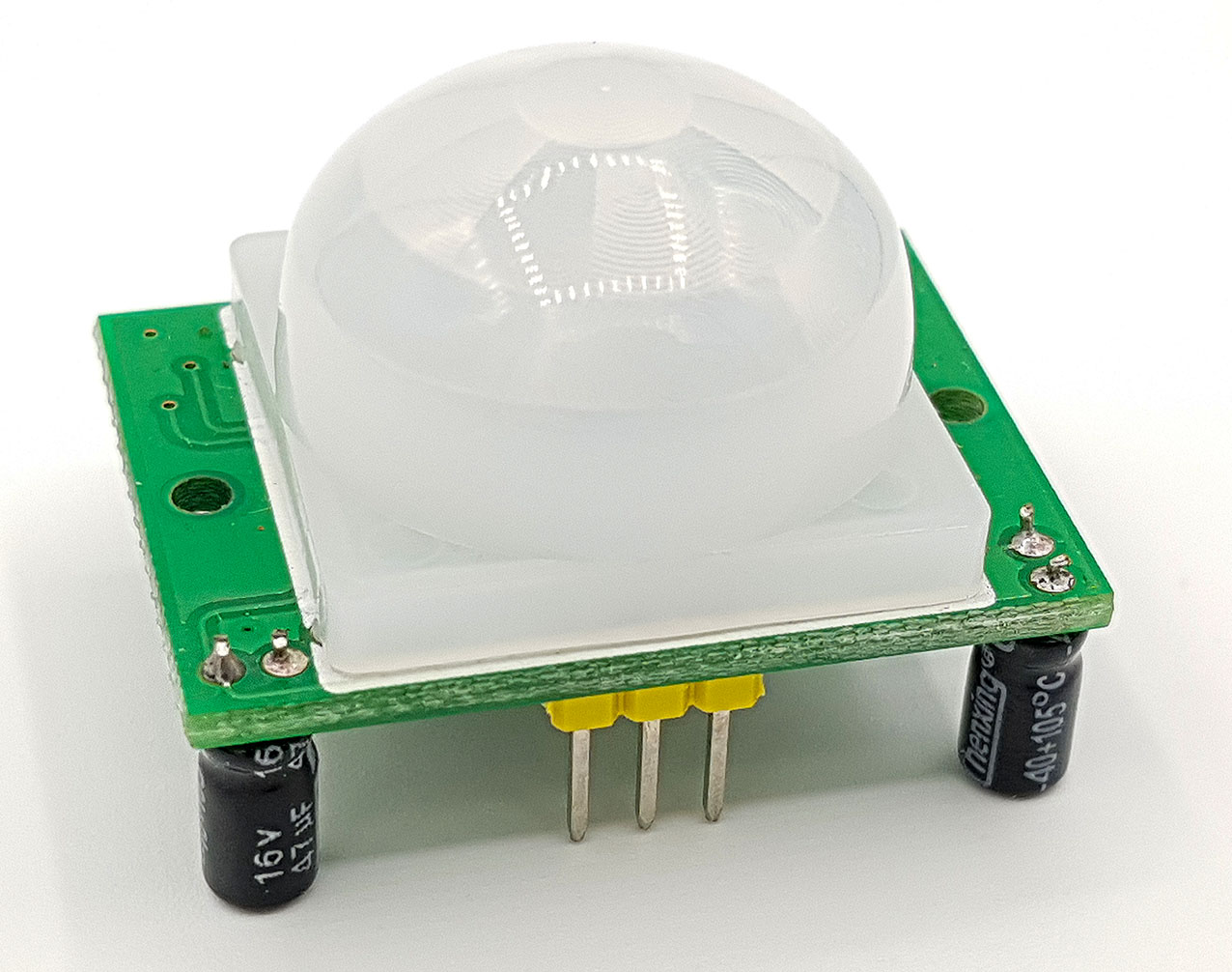
A deeper look into the HC-SR501
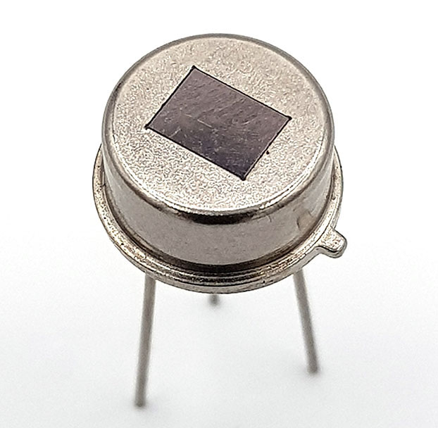
The heart of the module is the actual infrared sensor, which can also be purchased separately.
Since I was curious, I sacrificed a module and opened the sensor with my Dremel miniflex:

The two pyroelectric crystals can be clearly seen. By the way, lithium tantalate (LiTaO3) is mostly used.
Then I took a closer look at the caps. There are two versions here. One is reminiscent of a football, the other is a Fresnel step lens, as known from headlights or projectors, for example.

To check how the lenses work, I put one of the caps through a cardboard with its dome and made a “canvas” of butter bread paper at the back. Illuminated from the front, you can easily see the focal points of the individual lenses:

More about PIR detectors can be found here on Wikipedia.
Module properties
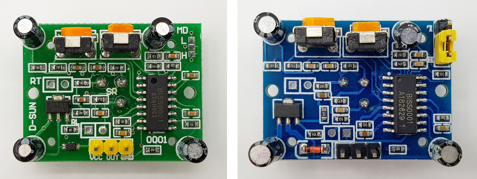
No matter from which source you get an HC-SR501 – they look pretty much the same. Apart from the color and the design of the cap, the biggest visible difference is the design of the jumper at the top right, namely sometimes with pins for switching and sometimes without pins for soldering. I will come to the invisible differences later.
Specification of the HC-SR501
- Power supply: 4.5 – 20 volts at VCC and GND (sometimes you find slightly different data)
- Range: max. approx. 7 meters, can be set down to approx. 4 meters
- Signal level: 3.3 volts (motion) / 0 volts (no motion) at OUT
- Signal length: usually 5 – 300 seconds is specified, in my experience is approx. 2 – 500 seconds
- Power consumption: 60 – 70 µA in waiting state; with motion detection in the short term more, but always < 1 milliampere
- Detection modes: Single trigger or repeatable trigger (explanation below)
- “Warm-up time”: After connecting to the power supply, the module takes 30 – 60 seconds to be ready for use. During this time, OUT goes to HIGH a few times.
- Lockout time: 0.2 or 3 seconds, depending on model
The range depends among other things on the size and heat radiation of the objects to be detected. For example, you cannot control the range down to 4 meters and then be sure that everything is detected below this value and above nothing. You have to play around a little and find the setting that best suits the application.
Since the signal time can be set quite long, the typical application “light is on for x minutes if motion detected” does not require a microcontroller but only a relay or transistor (how boring!).
Settings for the HC-SR501
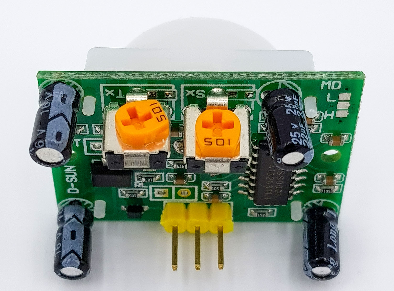
The length of the signal is set on the potentiometer marked “T” (time). A clockwise rotation lengthens the signal duration. The potentiometer marked “S” sets sensitivity. Again, a clockwise rotation increases the value. Some modules do not have any marking, but the potentiometers are always arranged as shown above.
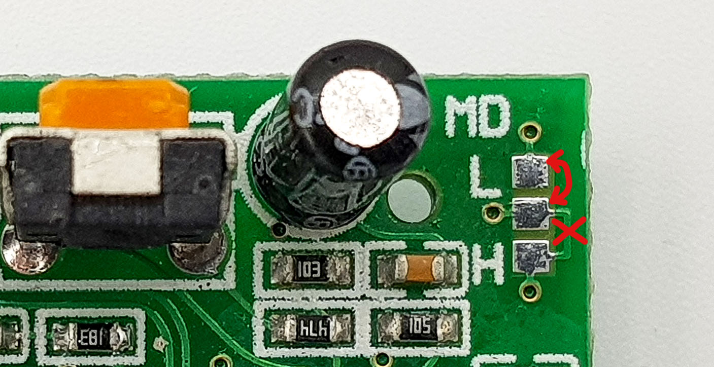
Operating modes single and repeatable trigger
The “Single Trigger” and “Reapeatable Trigger” operating modes can be set by the jumper at the top right. If the middle contact is connected to “H”, the repeatable trigger mode is set. Accordingly, the single trigger mode is set when it is connected to “L”. After a motion detection, the OUT pin goes to HIGH for the set time. If the Repeatable Trigger mode is active, further movements can be detected during this time of signal output. With each detected motion, the output time starts again from zero. If there is continuous motion, the OUT signal remains continuously HIGH. In single trigger mode, on the other hand, no movement can be detected during signal output. Accordingly, with this setting, the OUT signal goes LOW even with continuous motion in the meantime.
For the modules without pins on the jumper, the repeatable trigger mode is preset. To switch, you not only need to connect the middle contact with “L”, but also to cut the line to “H”. This can be done with a razor blade or a cutter knife with a fresh blade (be careful!).
If the OUT signal has gone to LOW, the HC-SR501 is locked for a short time and cannot detect any movements. This behavior is independent of the mode.
The following diagram shall illustrate this. In both modes, motion 1 triggers a signal. During the subsequent locking time (“locked”) the second motion has no effect. Motion 3 triggers a signal. The difference is the motion 4. In single trigger mode it has no effect, in repeatable trigger mode the signal output is extended.

So much for the theory….
As described above, you can read it everywhere. In my experience, however, the situation is still a bit more complex. If a motion occurs in the detection area during the lock out time, OUT sometimes goes to “HIGH” after the lock out period has ended, even though there is no movement at this moment. The phenomenon occurs especially when you are close to the sensor. When I was playing around with the detector settings on my desk, I noticed this and it seems no one has described this phenomenon. So don’t be surprised. I don’t know exactly why this happens, but I would suspect that the crystal, which has been warmed up by the motion, will take some time to return to its equilibrium temperature. A shadow of motion or an afterglow, so to speak.
HC-SR501 modules with different locking times
Some modules I tested have a lock time of about 3 seconds, others have a lock time of only 0.2 seconds. It seems that the models with pins on the jumper belong to the group with a lock time of 3 seconds and the others to the group with 0.2 seconds lock time. This does not mean, however, that the latter can achieve a particularly high detection frequency. The “afterglow” effect described above even leads to the fact that one can cause double triggering when setting minimum signal time. If this happens a motion triggers a HIGH at OUT, the detector goes into lock mode for a short time (i.e. LOW) and then the signal goes HIGH again although there is no motion anymore.
I find the available data sheets quite confusing (e.g. For example, this one), the content of which is literally copied out everywhere in product descriptions and partly also in blogs:

Probably nobody understands that and that’s why it’s just copied. Or can you explain it to me?
Because of these peculiarities, it is safest to react to the LOW to HIGH change to OUT and then ignore everything that happens at OUT for at least 5 seconds. So, something like this:
int triggerPin = 2;

void setup() {
  pinMode(triggerPin, INPUT);
}

void loop() {
  if(digitalRead(triggerPin)==HIGH){
    yourActions();
    delay(5000);
  }
}

void yourActions(){
  // your Action, e.g. switch a light on, alert, etc.
}
or like this:
byte interruptPin=2;
volatile bool motion = false;

void setup() {
  pinMode(interruptPin, INPUT);
  attachInterrupt(digitalPinToInterrupt(interruptPin), motionDetected, RISING);
}

void loop() {
  if(motion){
    yourActions();
    delay(5000);
    motion=false;
  }
}

void yourActions(){
  // insert your code
}

void motionDetected(){
  motion=true;
}
For the sake of completeness, here is the wiring, even if I think I could save it:

Acknowledgement
I have composed my post picture from a series of pictures from Pixabay:
- The alarm siren is from Wolfgang Vogt
- I owe the burglar to Peggy and Marco Lachmann-Anke
- The treasure chest is taken from Clker-Free-Vector-Images