
About the post
In my series of posts about light, gesture, motion and distance sensors, which I will conclude with an overall overview, I would like to report this time on the VL6180X module. Sometimes you also come across the designation VL6180, i.e. without “X”. However, this is always the same component.
First I will focus on the properties of the actual VL6180X, then the modules. Finally, I will introduce a library with which you can easily control this device. I used a Sparkfun library as the basis, which I expanded with interrupt functions.
Basics
The measuring principle
The VL6180X measures distances using the ToF (Time-of-Flight) method. Incidentally, the picture for this post at the top shall also indicate this. The VL6180X uses an infrared laser whose reflected light is evaluated in terms of its flight time to calculate the distance. In principle, similar to the well-known ultrasonic sensor HC-SR04. But since we are dealing here with radiation at the speed of light, the obvious question arises how to measure such short flight times with a low-cost component – it’s amazing, but it works. If you are interested in the details of the method, you can read an article about it here or get smart here on Wikipedia.
In addition, the VL6180X can measure ambient light (ALS) via a photodiode. The measured values can then be converted into lux values.
You get the VL6180X modules e.g. here at Amazon in a quite large price range. The cheapest ones are 6 – 7 euros including shipping.
As always, I also recommend a look at the data sheet. Because often – and this is also the case here – one discovers that components can do much more than is implemented in libraries.
Features of the VL6180X
The VL6180X has a lot of setting options. I will mention only what I consider to be the most important parameters. Many of the parameters are not implemented as public functions in the Sparkfun or my modified library. If you want to change them, you need to modify the default values directly in the library.
Range and measurement modes
According to the data sheet, the VL6180X measures distances up to 10 cm with millimeter accuracy. The modules I tried, had a range of almost 20 cm. This is consistent with information from other sources that I have found. If you need longer ranges up to 200 cm, you can reach for the “big brothers” VL53L0X or VL53L1X. I will deal with these in another post. Communication is carried out via I2C.
Both the measurement of the light (ALS) and the distance (range) can be done as a single shot or in a continuous mode. The manufacturer recommends not to measure light and distance in parallel continuously, but to switch to the so-called interleaved mode. In interleaved mode, ALS and range measurements are performed sequentially at regular intervals. Measurements in continuous and interleaved mode are particularly suitable if you want to monitor light or distance by the interrupt function.
For the distance measurement, the measuring time (max convergence time) can be set. The further the distance and the worse the reflection, the longer it takes an accurate measurement. The data sheet includes tables for this. In my experience, however, you are already doing very well with the presets. Ultimately, of course, the requirements depend on your specific application.
Ambient light measurement
You can also set the measurement time (integration period) for light measurement. This is similar to the TSL2561presented in my last post. The default value is 100 ms, which corresponds to the upper end of the recommended range of 50 – 100 ms according to the data sheet. In addition, you can also set various gain factors if necessary (GAIN_x, see example sketch).
The hstory buffer
A so-called history buffer stores the last eight light readings (16 bits) or the last sixteen distance values (8 bits) if the function is activated. The history buffer can be switched on and off, read and emptied manually. I used the history buffer for the interrupt function. You can use the data from the history buffer also to evaluate very simple gestures (approximation vs. moving away).
Cross talk compensation
If you install the VL6180X behind a glass pane, the measurement results can be falsified (cross talk). However, this effect can be compensated. The procedure for this is described in the data sheet. However, this feature is not implemented in the library.
Interrupts
Interrupts can be set for light and distance measurement. You can define a lower threshold, an upper threshold or a window. In addition, you can trigger an interrupt for each completed measurement.
I2C address
The default I2C address of the VL6180X is 0x29. Interestingly, you can change the address freely via corresponding register entries. Usually for other I2C devices this works via address pins. The corresponding public function changeAddress(alt,neu) is implemented in the library. Actually, the new address should be stored permanently. The change of address worked for me, but my module “forgot” its new address again when I cut off the power supply. What a pity. An I2C address scanner can be found here, if you also want to play around with the function. Maybe it works with your modules.
VL6180X Modules
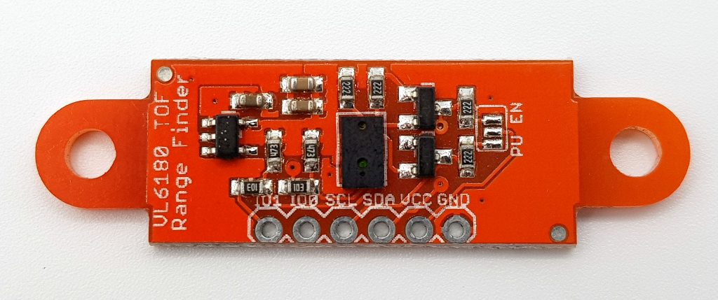
You get VL6180X modules in different shapes and sizes, but most have at least the same pins:
- VCC/GND: in contrast to the bare VL6180X ICs, which should be operated between 2.7 and 2.9 volts, most modules (not all, please check!) tolerate between 2.8 and 5.5 volts.
- SDA/SCL: I2C connection lines, pull-up resistors may be required. Some modules, such as the model shown, have integrated pull-ups. To activate them, you need to connect the contacts in the “PU EN” jumper area.
- GPIO0 (or “IO0” or only “0”):
- can be configured as an “off switch”
- can be configured as an interrupt pin
- Setting the signal polarity (active-low / active-high)
- GPIO1 (or “IO1” or “1”):
- can be configured as an interrupt pin
- Setting the signal polarity
Control with the (modified) Sparkfun library
There are a number of libraries on Github, e.g. Sparkfun, Adafruit, Pololu and stm32duino. The latter seems very complete, but – at least for me – it is quite difficult to “digest” because there are no examples. You find it here, and you can make your own mind.
Unfortunately, I couldn’t find any other that had implemented the interrupt function. Finally, I took the Sparkfun library and expanded it. The original can be found here on Github. You can get my extended version VL6180X_WE with interrupt function here or directly from the library management of the Arduino IDE.
Wiring
The wiring shown here works for both example sketches. It requires that the module works with 5 volts and that the module provides pull-up resistors for the I2C lines.

Example sketch for distance and light measurement
The first sketch shows how to perform simple light and distance measurements in single shot mode (also called polling mode). First the required libraries are integrated, then the VL6180X object “sensor” is created.
You can also omit the part that provides the information about the module. I took it from the original Sparkfun example sketch. The functions VL6180xInit() and VL6180xDefaultSettings() make settings as recommended by the manufacturer STMicroelectronics in the Application Note Document AN4545. The list of settings can be found there from page 24 (for those interested).
The function getAmbientLight(gain) does the light measurement. Only the gain is publicly accessible as a parameter. If you want to change more, you have to do it directly in the library. You query the distance with getDistance().
/******************************************************************************
 * VL6180X_WE_demo.ino
 * Based on SparkFun's example
 * Only Changes:
 *  - Baud rate changed to 9600
 *  - Name of the library
 *
 * Original library and examples:
 * https://github.com/sparkfun/SparkFun_ToF_Range_Finder-VL6180_Arduino_Library
 *
*******************************************************************************/
#include <Wire.h>
#include <VL6180X_WE.h>

#define VL6180X_ADDRESS 0x29

VL6180xIdentification identification;
VL6180x sensor(VL6180X_ADDRESS);

void setup() {

  Serial.begin(9600); //Start Serial at 9600bps
  Wire.begin(); //Start I2C library
  delay(100); // delay .1s

  sensor.getIdentification(&identification); // Retrieve manufacture info from device memory
  printIdentification(&identification); // Helper function to print all the Module information

  if(sensor.VL6180xInit() != 0){
    Serial.println("FAILED TO INITALIZE"); //Initialize device and check for errors
  }

  sensor.VL6180xDefaultSettings(); //Load default settings to get started.
  delay(100); // delay 0.1s
}

void loop() {

  //Get Ambient Light level and report in LUX
  Serial.print("Ambient Light Level (Lux) = ");

  //Input GAIN for light levels,
  // GAIN_20     // Actual ALS Gain of 20
  // GAIN_10     // Actual ALS Gain of 10.32
  // GAIN_5      // Actual ALS Gain of 5.21
  // GAIN_2_5    // Actual ALS Gain of 2.60
  // GAIN_1_67   // Actual ALS Gain of 1.72
  // GAIN_1_25   // Actual ALS Gain of 1.28
  // GAIN_1      // Actual ALS Gain of 1.01
  // GAIN_40     // Actual ALS Gain of 40

  Serial.println( sensor.getAmbientLight(GAIN_1) );

  //Get Distance and report in mm
  Serial.print("Distance measured (mm) = ");
  Serial.println( sensor.getDistance() );

  delay(500);
};

void printIdentification(struct VL6180xIdentification *temp){
  Serial.print("Model ID = ");
  Serial.println(temp->idModel);

  Serial.print("Model Rev = ");
  Serial.print(temp->idModelRevMajor);
  Serial.print(".");
  Serial.println(temp->idModelRevMinor);

  Serial.print("Module Rev = ");
  Serial.print(temp->idModuleRevMajor);
  Serial.print(".");
  Serial.println(temp->idModuleRevMinor);

  Serial.print("Manufacture Date = ");
  Serial.print((temp->idDate >> 3) & 0x001F);
  Serial.print("/");
  Serial.print((temp->idDate >> 8) & 0x000F);
  Serial.print("/1");
  Serial.print((temp->idDate >> 12) & 0x000F);
  Serial.print(" Phase: ");
  Serial.println(temp->idDate & 0x0007);

  Serial.print("Manufacture Time (s)= ");
  Serial.println(temp->idTime * 2);
  Serial.println();
  Serial.println();
}
Example sketch for the interrupt function
To implement interrupts, I have had to add some additional functions to the library. In VL6180X_WE.h. I highlighted the new features in case someone is interested in the details.
Distance interrupt
If you want to use the interrupt function for proximity, you must first define a window outside which an interrupt is triggered. The function for this is called VL6180xSetDistInt(lower limit, upper limit). You set the limits in millimeters. If you only want to set a single threshold, then set 0 or 255 as the other because values beyond cannot occur.
Then you have to start the distance measurement in continuous mode with getDistanceContinously(). With this function, you can also query distance values whenever you want. A query by getDistance(), on the other hand, terminates the continuous mode.
I set the interrupt pin GPIO1 active-low. In case of an interrupt:
- an “Interrupt!” message appears on the serial monitor
- the LED connected to pin 13 lights up for one second
- the sketch queries the last value from the history buffer
You have to delete the interrupt manually.
It should be noted that the VL6180X continues the measurements despite the interrupt. So you must not let too much time pass between the interrupt event and the reading of the history buffer.
The history buffer is activated in the background when setting the continuous mode.
Ambient light interrupts
The interrupts for light measurement work in principle like distance interrupts. First, you comment lines 50, 51, 63 and 64 and uncomment the corresponding lines for the light interrupts. As described above, you should always measure only light or distance in continuous mode.
You now define a window in lux values beyond which an interrupt is triggered. Then you start the continuous mode for light measurement.
When reading history buffer for the light values, you must also pass the gain factor again. You must ensure that you pass the same gain factor with all functions.
Note: if you switch from light interrupts to distance interrupts, i.e. change the sketch and upload it, you may need to take the VL6180X off the current once. I don’t know the exact reason, but it seems resets do not reset all settings.
/******************************************************************************
 * Modified by Wolfgang (Wolle) Ewald
 * https://wolles-elektronikkiste.de/en/vl6180x-tof-proximity-and-ambient-light-sensor
 *
 * ****************************************************************************
 * Based on the Sparkfun library example for the VL6180X:
 * https://github.com/sparkfun/SparkFun_ToF_Range_Finder-VL6180_Arduino_Library
 *
 ******************************************************************************/

#include <Wire.h>

#include <VL6180X_WE.h>
#define VL6180X_ADDRESS 0x29

VL6180xIdentification identification;
VL6180x sensor(VL6180X_ADDRESS);
int interruptPin = 2;
int ledPin = 13;
volatile bool event = false;
int gain;

#if defined(ESP8266) || defined(ESP32)
void IRAM_ATTR blink(){
#else
void blink(){
#endif
  event = true;
}

void setup() {
  pinMode(ledPin, OUTPUT);
  pinMode(interruptPin, INPUT_PULLUP);
  attachInterrupt(digitalPinToInterrupt(interruptPin), blink, FALLING);
  Serial.begin(9600);
  Wire.begin(); //Start I2C library

  if(sensor.VL6180xInit() != 0){
    Serial.println("FAILED TO INITALIZE"); //Initialize device and check for errors
    }

  sensor.VL6180xDefaultSettings(); //Load default settings to get started.

  delay(100); // delay 0.1s

  //Input GAIN for light levels,
  // GAIN_20     // Actual ALS Gain of 20
  // GAIN_10     // Actual ALS Gain of 10.32
  // GAIN_5      // Actual ALS Gain of 5.21
  // GAIN_2_5    // Actual ALS Gain of 2.60
  // GAIN_1_67   // Actual ALS Gain of 1.72
  // GAIN_1_25   // Actual ALS Gain of 1.28
  // GAIN_1      // Actual ALS Gain of 1.01
  // GAIN_40     // ActualALS Gain of 40

  /* Range Threshold Interrupt:
   * The interrupt is set up with VL6180xSetDistInt(low limit / high limit);
   * The interrupt is triggered if the measured distance value is OUTSIDE these
   * limits. Keep in mind that the VL6180x will return a distance of 255 if
   * nothing is in the measuring range.
   * Examples:
   * low limit = 50, high limit = 150 => interrupt is triggered at < 50 and > 150
   * low limit = 50, high limit = 255 => interrupt is triggered at < 50
   * low limit = 0, high limit = 50 => interrupts is triggered at > 50
   */
  sensor.VL6180xSetDistInt(50,150);
  sensor.getDistanceContinously();

  // ALS Threshold Interrupt:
  // sensor.VL6180xSetALSInt(GAIN_1,30,200);
  // sensor.getAmbientLightContinously(GAIN_1);
}

void loop() {
   if(event){
    Serial.println("Interrupt!");
    // Serial.print("Last ALS Value: ");
    // Serial.println(sensor.getLastAmbientLightFromHistory(GAIN_1));
    Serial.print("Last Distance Value: ");
    Serial.println(sensor.getLastDistanceFromHistory());
    digitalWrite(ledPin, HIGH);
    delay(1000);
    digitalWrite(ledPin, LOW);
    event = false;
    sensor.VL6180xClearInterrupt();
  }
}
Acknowledgement
The nice stopwatch on the main post image is from Sadia on Pixabay. Thank you!
Thanks also to Sparkfun for the (basic) library and for the Fritzing VL6180 component.