About this Post
This article about the TinyCore board package from MCUDude is now my third article about board packages for the classic ATtinys. So why another one? In 2019, I wrote about the attiny board package from David A. Mellis. It works wonderfully but only covers part of the classic ATtiny family. In 2022, I dedicated an article to the great ATtinyCore board package from Spence Konde. Unfortunately, there is a problem with the latest version of the package and the Arduino IDE 2.x. In addition, the package does not appear to be maintained, at least at present. Good reasons to discuss an alternative.
TinyCore is based on ATtinyCore and includes several improvements, such as the space-saving Urboot bootloader.
Here’s what you can expect in detail:
- The classic ATtinys
- Pinout / Pinmapping
- Installing TinyCore in the Arduino IDE
- Burning the bootloader
- Uploading sketches
- Micronucleus Bootloader – Let us build a Digispark
- Further features of the TinyCore board package
This article repeats much of what I wrote about the MiniCore package in my last article. Regular readers may find this boring, but each post should be understandable on its own.
The classic ATtinys
TinyCore covers the following classic ATtinys and boards based on them:
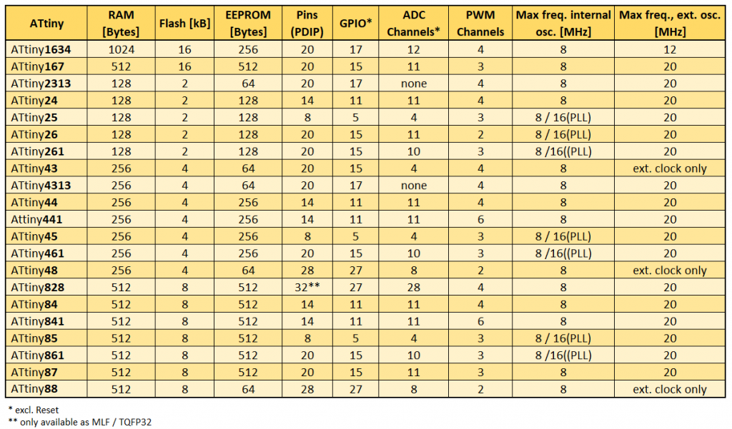
With their sometimes minuscule RAM and flash memory, the ATtinys seem somewhat outdated, yet they remain highly popular. From a technical point of view, the newer models in the tinyAVR® series 0 to 3 are almost always the better choice (see this article). However, the classic ATtinys are favoured by their widespread use and the resulting abundance of articles, tutorials, and forum posts. Added to this is their availability in PDIP version and their comparatively simple and therefore easy-to-understand architecture. In any case, as far as I’m concerned, they’re still worth writing a post about.
Pinout / Pinmapping
In this article, the ATtiny85 is my standard example. Here is the corresponding pinout diagram of the PDIP variant, which is also valid for the ATtiny45 and the ATtiny25:
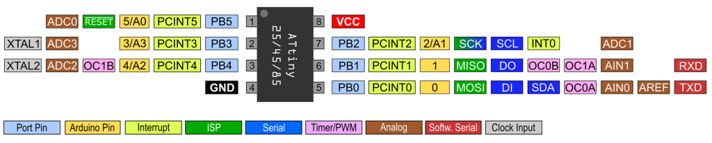
Some of the pin functions are defined on the hardware side, others are assigned via the board package. The pinout diagrams of the other ATtinys can be found here.
Installing TinyCore in the Arduino IDE
Installation is completed in two minutes:
- Go to File → Preferences and click on the green icon next to “Additional boards manager URLs”.
- Then enter the following as a separate line:
- https://mcudude.github.io/TinyCore/package_MCUdude_TinyCore_index.json
- Confirm twice by clicking on “OK”.
- Then go to the boards manager via the board icon on the left-hand side of the program window. Alternatively, you can navigate there via Tools → Board → Boards manager.
- Enter “TinyCore” in the search field and choose “TinyCore by MCUdude” among the hits.
- Click on “Install” – and that’s it.
Problems? Then you will find detailed instructions for installing board packages here.
Burning the bootloader
In my last post about the MiniCore board package, I covered the basics of bootloaders, fuses and programming methods in quite some detail. If you need or are interested, take a look here. In this article, I would just like to briefly summarize again:
- For uploading programs to a “naked” ATtiny you can use an ISP programmer or a USB-to-TTL adapter.
- To use the USB-to-TTL adapter, you must first burn a bootloader. This in turn requires an ISP programmer. In other words, there is no way around the programmer.
- “Burning the bootloader” in the Arduino IDE is more than just uploading the bootloader to the program memory. It also sets the so-called fuses, which determine the clock speed and clock source, among other things.
- Therefore: When changing basic settings, it is also necessary to burn the bootloader if you want to upload programs via ISP.
- If you upload a program via ISP, any existing bootloader will be deleted.
So, no matter which board or microcontroller you want to use with MiniCore, and no matter whether with bootloader or not: First you have to burn the bootloader.
The good news is: you can turn an Arduino board into an ISP programmer. The bad news is that the whole thing is quite fiddly and you can make mistakes in many places. I therefore recommend investing in a programmer. There are some available for just a few euros. Here you can find a list of programmers that I successfully tried out in my last post.
Burning the bootloader with an “Arduino as ISP”
In the following, I will show you how to turn a classic Arduino Nano into an ISP programmer. This also works with an Arduino UNO R3 and many other Arduino boards. There are a few differences in the details of some boards. There’s an article on this topic on the Arduino website that I definitely recommend reading.
Step 1: You select the Arduino Nano (the programmer) as the board in the Arduino IDE and connect it to the PC. Also set the correct port. It’s best to do this without connecting the Arduino to anything else.
Step 2: Go to File → Examples → Built-in examples, open the ArduinoISP sketch, and upload it.
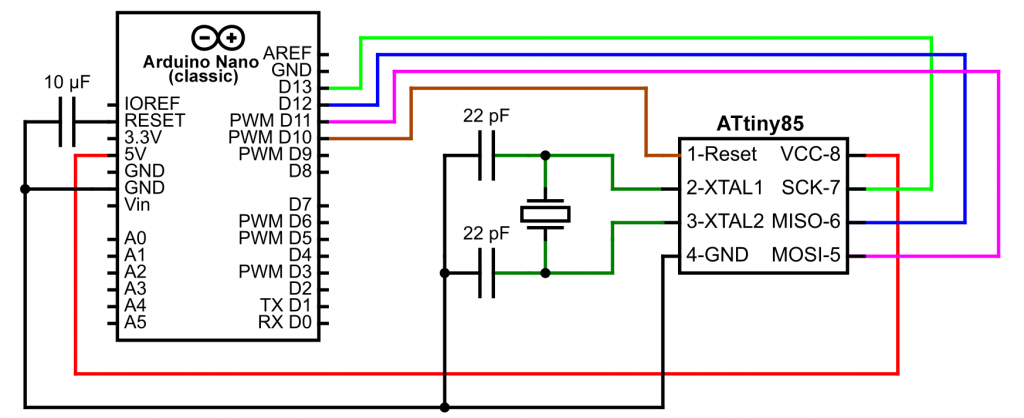
Step 3: Connect the Arduino Nano to the ATtiny85 as follows (you don’t need the LED here yet):
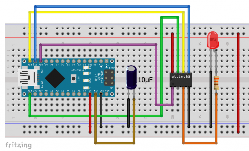
If you are using a different ATtiny, find the MISO, MOSI, SCK, RESET, VCC and GND pins in the respective pinout diagram and wire it accordingly.
Step 4: Now select the TinyCore package and apply the following settings for the ATtiny85 (your target):
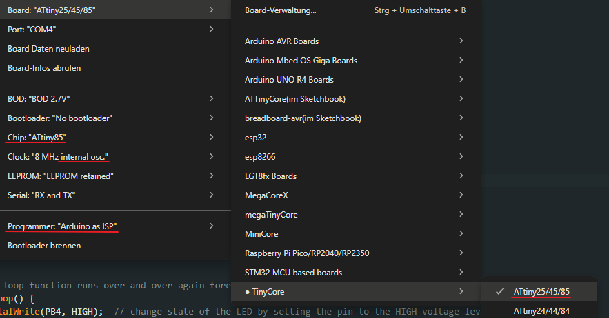
If you want to upload your sketches later via USB-to-TTL adapter, select “Yes” as option for the bootloader.
Step 5: Click on “Burn Bootloader”.
Using external oscillators
If you want to use an external crystal, connect the ATtiny as shown below and select the corresponding option for “Clock” when burning the bootloader. With an additional LED, pin availability on ATtiny85 gets tight. You will have to share a pin with MISO, MOSI, or SCK.
Burning the bootloader with a dedicated programmer
As mentioned before, burning the bootloader and uploading sketches via ISP is much easier with a “real” programmer.
The programmers have a 6-pin and/or 10-pin connector:
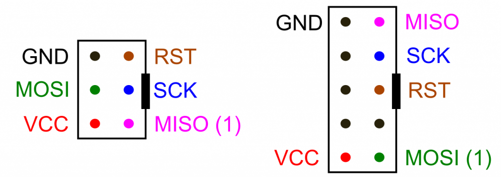
Connect the pins to their counterparts on the ATtiny.
As you can easily get confused with the pins, I recommend using an adapter for breadboard circuits:
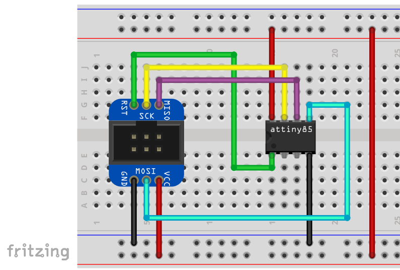
In the above instructions for burning the bootloader, start with step 4 and set the correct programmer. For some programmers you have to select the correct port, other programmers do not appear under “Port” in “Tools”. You will need to install a driver for most programmers. You can read more about this topic in my last post.
Uploading sketches
Uploading sketches via ISP
Uploading via ISP is straightforward. Leave both the ATtiny connection and the settings in the Arduino IDE as they were when you burned the bootloader. Start the upload using the keyboard shortcut CTRL/Shift/U or via Sketch → “Upload with Programmer”. It also worked for me using the “normal” upload method (i.e. the arrow icon or Ctrl+U), but I can’t guarantee that it will work that way with every programmer.
A blink sketch is suitable for testing. This will also show you whether everything is OK with the clock settings.
void setup() {
  // Serial.begin(9600);
  pinMode(PB4, OUTPUT);
}

void loop() {
  digitalWrite(PB4, HIGH); // PB4 or 4 or A2
  delay(1000);
  digitalWrite(PB4, LOW);
  delay(1000);
  // Serial.println("Hello World");
}
The advantage of the ISP method is that it saves the space in the flash memory that the bootloader would occupy.r. The Urboot bootloader used by TinyCore is already relatively slim with its 256 bytes, but that is still one-eighth of the ATtiny2xx’s program memory. The downside, however, is that you usually cannot connect to the serial monitor via the ISP port (a workaround for “Arduino as ISP” is explained below). If you uncomment lines 2 and 11, you won’t see any output.
And don’t forget: Uploading a sketch via ISP overwrites any existing bootloader.
Uploading sketches with a USB-to-TTL adapter
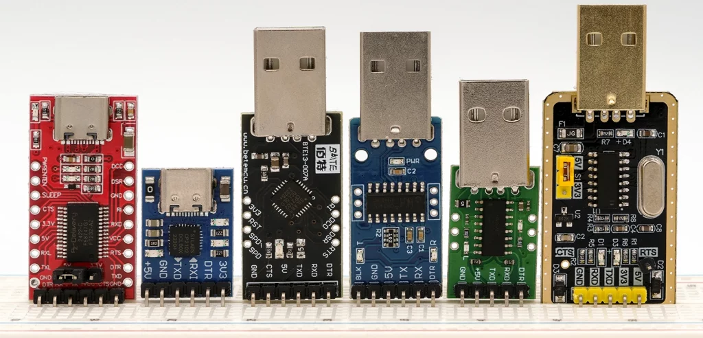
First, you’ll need a USB-to-TTL adapter to upload your sketches; these are available for just a few euros. I recommend models that have a DTR pin. In theory, you can manage without one, but it’s inconvenient. In my last post, I wrote a bit more about the adapters.
A prerequisite for uploading via USB-to-TTL adapter is the presence of the bootloader on your ATtiny. You cannot burn the bootloader with the USB-to-TTL adapter, but only with a programmer and the procedure described above. Select the option “Bootloader: Yes”. Once this is done, connect the USB-to-TTL adapter to the ATtiny as follows:
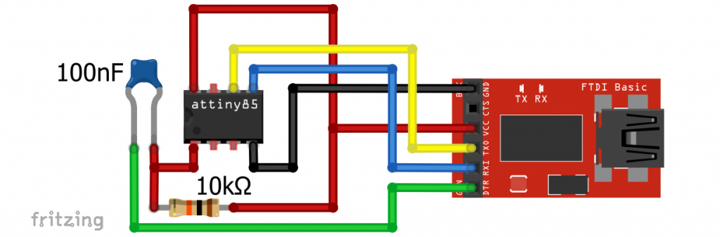
100 nF is generally recommended for the capacitor on the reset pin. If you don’t have one, you can try a larger one. For me it also worked with 10 µF.
If you don’t have a DTR pin, leave out the capacitor and the pull-up resistor on Reset. When uploading, wait until the message “Warning: Attempt x of 10: not in sync” appears and then briefly pull the reset pin to GND.
The USB-to-TTL adapter allows you to output to the serial monitor. To test this, uncomment lines 2 and 11 in blink_serial_test.ino.
Uploading via ISP and using the serial monitor
Of course, you can also upload your sketches via ISP and use the serial monitor with an additional USB-to-TTL adapter. You only need to connect the GND, RX and TX pins of the USB-to-TTL adapter. You connect VCC if the ATtiny is not already supplied with power via the programmer. I was able to connect the programmer and adapter at the same time without any problems. When switching between uploading and serial output, you must select the correct ports.
Saving SRAM
If you only want to output to the serial monitor but not send anything from it, you can select the “TX only” option under Serial in the settings. This saves 36 bytes of SRAM, which would otherwise be reserved for the RX buffer. And if you have enough flash, use the F macro: Serial.print(F("......"));.
Changing the TX pin
You can assign TX to another pin using Serial.setTxBit(PBn);. Call this function before Serial.begin(). However, this is irrelevant for the program upload. For this step, TX is on the preset pin. After the upload, you can reconnect TX.
Using the serial monitor via “Arduino as ISP”
I am not a fan of “Arduino as ISP”, but I would still like to show you a variant of this method that also allows you to use the serial monitor. The programmer uses SoftwareSerial.
I found this variant here in the German Arduino forum. First you have to download the modified version of the ArduinoISP sketch from there (alternatively, here from GitHub). The SoftwareSerial communication requires an additional data line. The RX of the programmer (i.e. the Arduino board) is preset to pin D4. You can change this in the first lines of the modified ArduinoISP sketch. TX of the programmer is preset to the virtual pin 99. If you want to send messages from the serial monitor to the target (the ATtiny), you must change this to a real pin and set up a data line.
Please note that the serial baud rate of the programmer is preset to 19200 baud. You must set this baud rate in the serial monitor, or you can change the default setting in the ArduinoISP sketch to setup().
And this is what a test sketch for your ATtiny could look like:
#include<SoftwareSerial.h>
SoftwareSerial softSerial(99, 4); // RX, TX - we don't need RX

void setup() {
  softSerial.begin(9600); // set Baud 19200 in Serial Monitor!!!
  pinMode(PB3, OUTPUT);
}

void loop() {
  digitalWrite(PB3, HIGH);
  delay(1000);
  digitalWrite(PB3, LOW);
  delay(1000);
  softSerial.println("Hello World");
}
Note that RX is preset to the virtual pin 99 here.
The disadvantage of this method is a slightly higher consumption of SRAM for the RX and TX buffers. There is also a small additional consumption of flash memory.
Micronucleus Bootloader – Let us build a Digispark
The Micronucleus is a bootloader used on the Digispark (ATtiny85) and MH-Tiny (ATtiny88) boards. Thereby the ATtiny is programmed directly via USB without adapter. To make this possible, the Micronucleus uses a technique called VUSB. This means that components that do not have a hardware USB interface can also be addressed via USB.
The Digispark could once be integrated into the Arduino IDE using its own board package. Extensive documentation was available on the Digistump website. After that documentation was no longer available, users could continue working with Spence Konde’s ATtinyCore. However, that approach no longer works either. So it’s great news that TinyCore has integrated the Micronucleus bootloader.
The downside of the Micronucleus — just like with the Urboot bootloader — is that it reduces the amount of available flash memory. Unfortunately, the Micronucleus requires even more memory, specifically about 1,400 bytes.
Preparations
Burning the Micronucleus Bootloader
Of course, you can use commercially available Digispark or MH-Tiny boards. But I’d also like to show you how to build a Digispark yourself.
If you are not using a pre-assembled board, you must first burn the Micronucleus bootloader via ISP using a programmer. To do this, select “Micronucleus (16 MHz PLL)” as the bootloader. Alternative clock speeds are not supported.
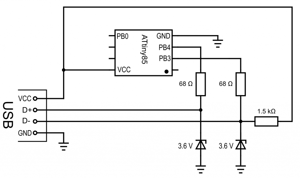
Circuit for the DIY Digispark
In addition to the ATtiny85, you will need two 68 Ω resistors, one 1.5 kΩ resistor, and two 3.6-volt Zener diodes for the circuit. The Zener diodes are used to protect the USB interface of your computer because the data lines use 3.3 volts. So be careful what you do!
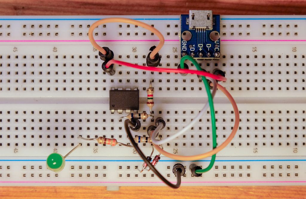
For the USB connection, I recommend using a USB breakout module. Here’s what the circuit looked like on the breadboard (with an additional LED on PB4):
Upgrading the Micronucleus bootloader
There is an improved version of the Micronucleus bootloader, but you cannot burn it directly via ISP. Instead, first burn the standard version as described above, and then follow these steps:
- Set the bootloader to: “Upgrade to the latest Micronucleus (16 MHz PLL)”.
- If your Digispark or DIY project is still connected to the PC, disconnect it.
- Select Tools → “Burn Bootloader”.
- You see the error message “Error: no device found, waiting 60 seconds for the device to be plugged in …”.
- Connect the (DIY) Digispark to the PC via USB within 60 seconds (not via ISP!).
Then the bootloader should be updated.
Driver issues?
If the bootloader upgrade or later the upload of sketches doesn’t work, it might be due to the driver. I had problems with this at first, anyway. If you’re using Windows, connect your Digispark to the PC and go to Device Manager. There, the Digispark should appear under “libusb-win32 Devices” as “Digispark Bootloader.” Double-click the entry, go to Driver → Driver Details. If something other than libusb0 (Version >= 1.4.0.0) is listed there, you can use Zadig to set this driver. I’ve described how to use Zadig here.
Uploading sketches
Disconnect the Digispark from the PC. Then click the upload arrow or use the keyboard shortcut “Ctrl+U.” You’ll see the error message again stating that no device was found. When you connect the Digispark to the PC via USB, the upload will start automatically.
Further features of the TinyCore board package
Actually, this was only the beginning, because up to now the article was only about basic settings and the program upload. I have already gone into a little detail about Serial, but not about I2C and SPI. Other important topics are Timer/PWM, the ADC, the EEPROM and Servo or Tone. The members of the classic ATtiny family differ quite significantly in terms of these functions. However, it would go beyond the scope of this article to go into this in detail.
The good news: TinyCore abstracts many of the functions. For example, in most cases you will not even notice whether an ATtiny has a “real” UART or I2C interface or not. TinyCore is also excellently documented. On GitHub you will not only find general information on the functions mentioned, but also detailed descriptions of the individual members of the ATtiny family. The numerous example sketches provided are also particularly helpful.
Other special features of the TinyCore package that I would like to point out are:
- Support of
printf(). - Implementation of pin macros, e.g.
digitalWrite(PIN_PB0, HIGH). - Settings for Brown-Out Detection (BOD).
- Non-erase option of the EEPROM when uploading sketches via ISP or when burning the bootloader.
- Calibration of the oscillator (OSCCAL).
- Debugging
- PlatformIO-Unterstützung
How you can support me
If you liked the article and would like to support me, please click here to find out how you can do so. This way you can help keep this site free of advertising.