About the post
In my last post I gave a quick introduction to Atmel Studio 7. The ability to debug is a big advantage over the Arduino IDE when working with Atmel Studio. Programming in C, on the other hand, can be a little daunting for die-hard Arduino followers. Some people would probably like to continue using the Arduino UNO and the “Arduino language” but still want to be able to use debugging for the Arduino. The good news:
- it’s possible, you can program the Arduino UNO with Atmel Studio
- you can import existing Arduino sketches
- you can track variables, run the sketch step by step and set breakpoints
And what’s the bad news?
- you need a programmer which supports debugging, and these are not quite cheap
- a small hardware intervention on the Arduino is necessary, which you have to undo if you want to program again using the Arduino IDE
- if the Arduino sketch contains libraries, there are a few things to keep in mind depending on the type of library
How to install Atmel Studio, I described in my last post. I had introduced various programmers for Atmel Studio in my penultimate post. Both topics are therefore omitted here.
Preparation of debugging for the Arduino Uno
Note: it’s best to read the whole post first and then decide whether you want to perform the following procedure. There is a potential risk that you will not be able to undo it. In this case, you will no longer be able to use the Arduino with the Arduino IDE.
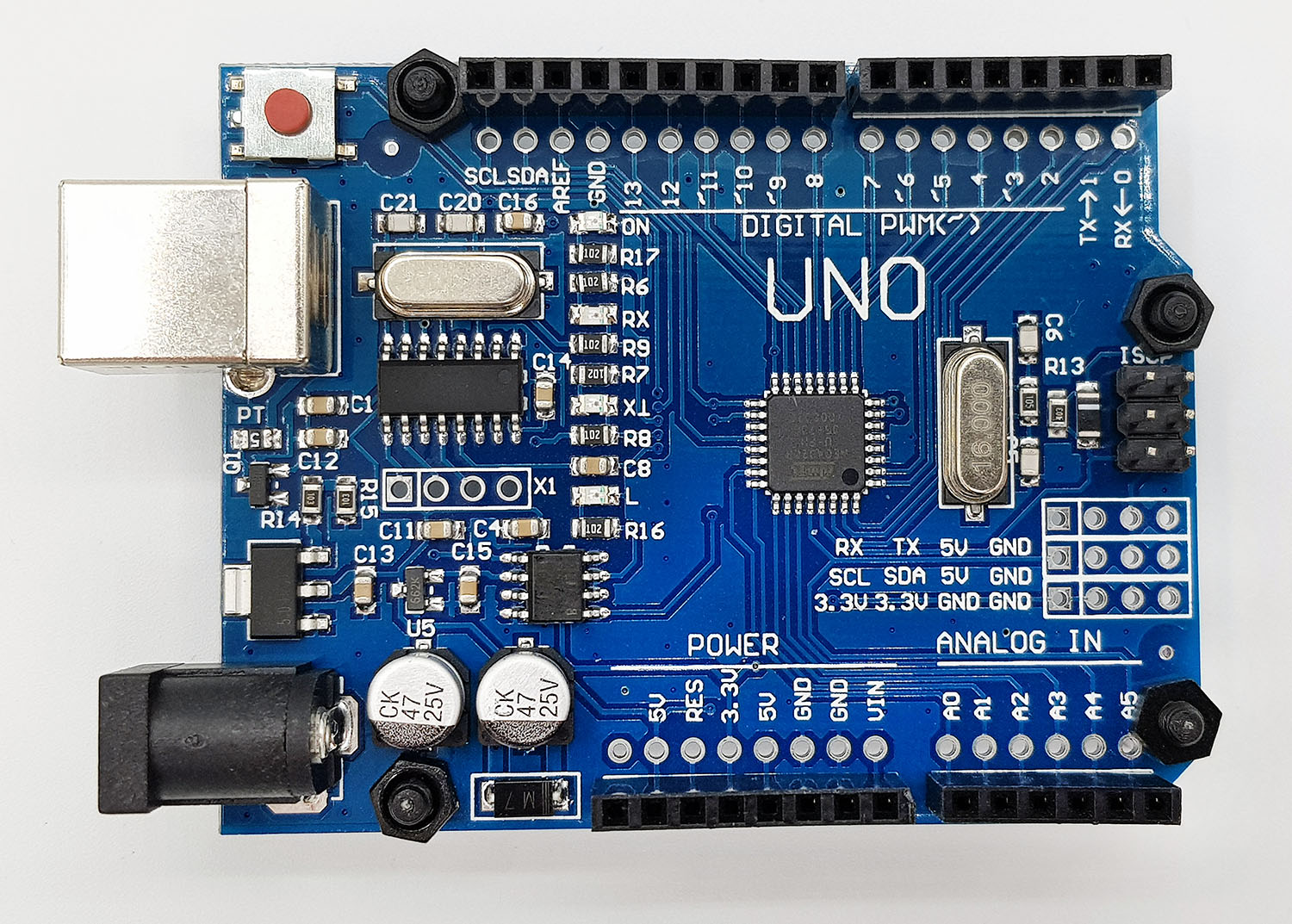
The way the Arduino UNO or the Arduino IDE handles the reset on the ATMega328P is unfortunately incompatible with Atmel Studio, which is related to the special bootloader of the Arduino. This would not be a problem in itself, as you can overwrite bootloaders, but this special feature has consequences for the wiring on the Arduino UNO board. However, it is quite easy to overcome this hurdle.
If you look at your Arduino UNO, you will find two soldering points in a white bordered area with the label “RESET EN” to the right of the 16 MHz oscillator. If you take a closer look, you will see that the two soldering points are connected with a small connection line. You have to cut this connection with a razor, scalpel or similar (caution!). Because I was impatient and had nothing else on hand, I took a not entirely new cutter knife. It worked, but is actually too rough.

How do I undo that?
There are three possibilities:
- Of course, you can simply solder the soldering points. However, this is not very convenient if you do this multiple times.
- I’ve seen in some posts that very skillful people have soldered two pins, which they connected with a jumper cap as needed.
- Not at all. You invest in a second Arduino UNO, which is only used for Atmel Studio. I chose this variant. After all, you get this device for less than ten euros. In addition, you have to replace the bootloader for each change (see below) and this is too tedious for me.
Not all UNO versions or clones work
Debugging for the Arduino using Atmel Studio only works on the hardware side with the UNOs, which have the dip variant of the ATmega328P. With the following variant it is not possible or at least I do not know how it works:
An application example
In a practical example, I want to show step-by-step how to import a sketch including libraries into Atmel Studio.
Different types of libraries
A simple Arduino Sketch without libraries can be uploaded to the Arduino UNO quite easily with Atmel Studio 7. For example, there is a Youtube video by Microchip (to which Atmel belongs). Including libraries is actually easy – if you know what to look out for. The first point to consider is that there are different libraries. On the one hand, these are those in line with the Arduino specification for libraries. They can be identified, for example, in the fact that in addition to the “.h” and “.cpp” files, there is also a file called “library.properties”. Other libraries, which consist only of “.h” and “.cpp” files, can also be included, but in a different way. Such libraries are mostly older, not specifically designed for Arduino or the author was too lazy.
An example sketch
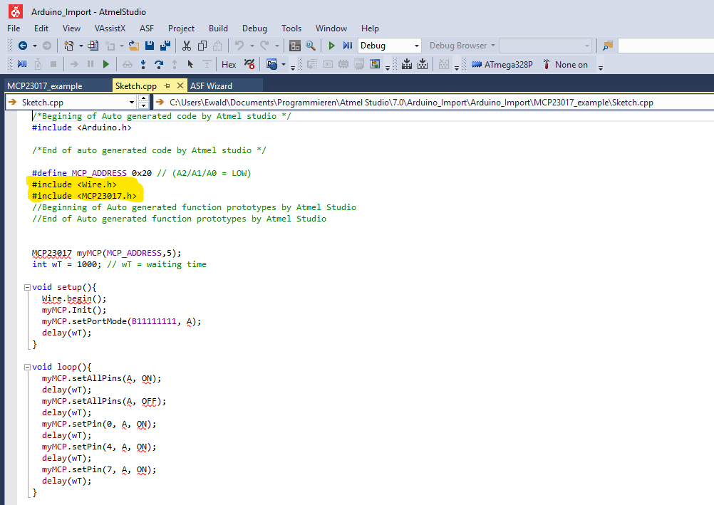
In my sample sketch, LEDs are switched at port A of an MCP23017 port expander. The sketch uses the Wire library because the MCP23017 is addressed by I2C. In addition, the sketch uses a self-written library (MCP23017) that does not meet the Arduino specification (update: that has change meanwhile! – But it still shows the principle and I did not find the time yet to take a different example). The library still works smoothly within the Arduino IDE.
#define MCP_ADDRESS 0x20 // (A2/A1/A0 = LOW)
#include <Wire.h>
#include <MCP23017.h>
MCP23017 myMCP(MCP_ADDRESS,5);
int wT = 1000; // wT = waiting time

void setup(){
  Wire.begin();
  myMCP.Init();
  myMCP.setPortMode(B11111111, A);
  delay(wT);
}

void loop(){
  myMCP.setAllPins(A, ON);
  delay(wT);
  myMCP.setAllPins(A, OFF);
  delay(wT);
  myMCP.setPin(0, A, ON);
  delay(wT);
  myMCP.setPin(4, A, ON);
  delay(wT);
  myMCP.setPin(7, A, ON);
  delay(wT);
}
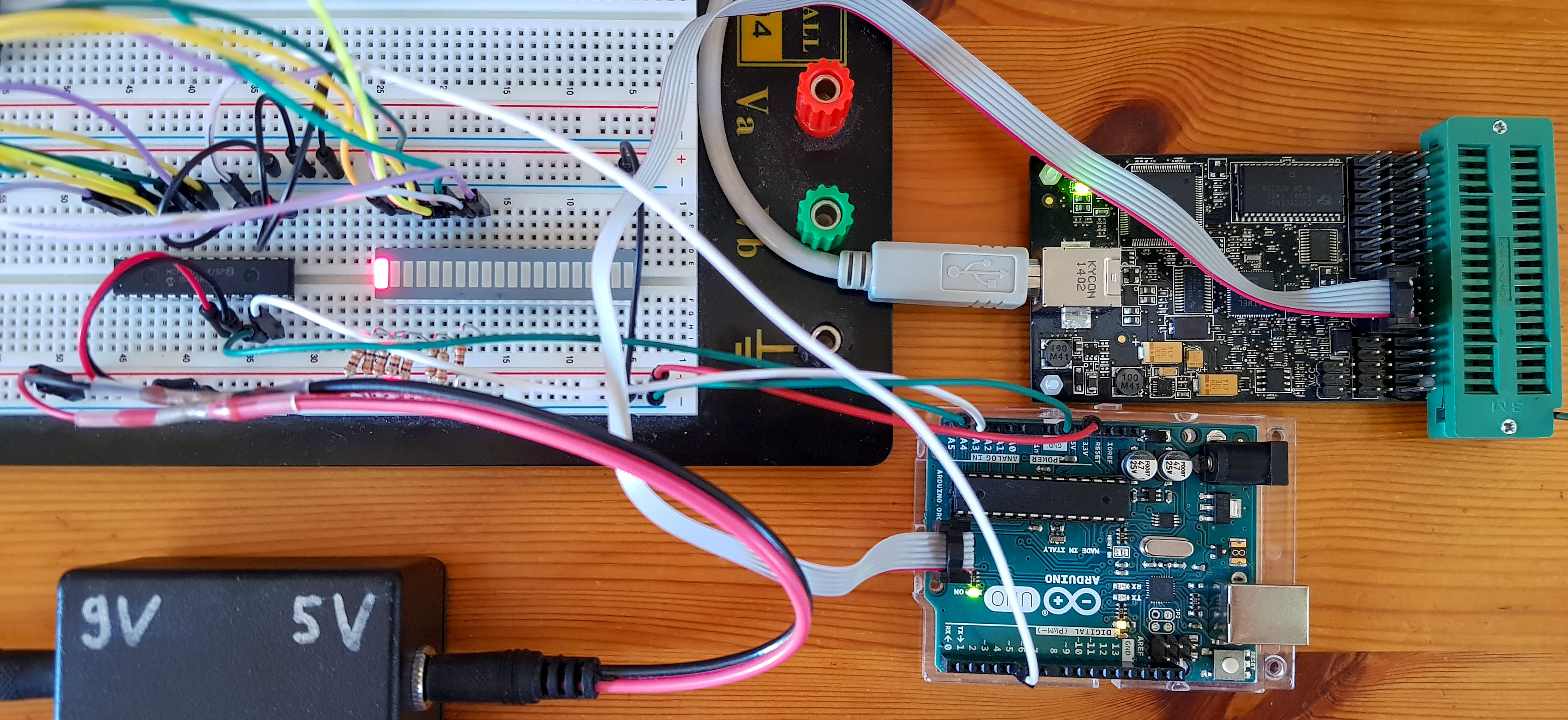
The wiring for the example sketch
It is only important to explain the principle of the import, but for the sake of completeness here is the wiring for the example:

If you want to replicate exactly this example, then here is the link to my post in which I deal with the MCP23017 and the library. You can also download the library directly from Github here. Alternatively, of course, you can choose any other sketch that contains libraries.
I will be revising the MCP23017 library soon to meet the specification (update: done). If you still want to follow this example, simply rename the file “library.properties” in the meantime so that Atmel Studio no longer identifies it as an Arduino library.
Importing the sketch and libraries into Atmel Studio
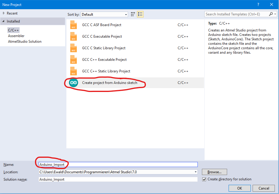
Enough of the preparations, now it’s time to use Atmel Studio 7. First, you start a new project.
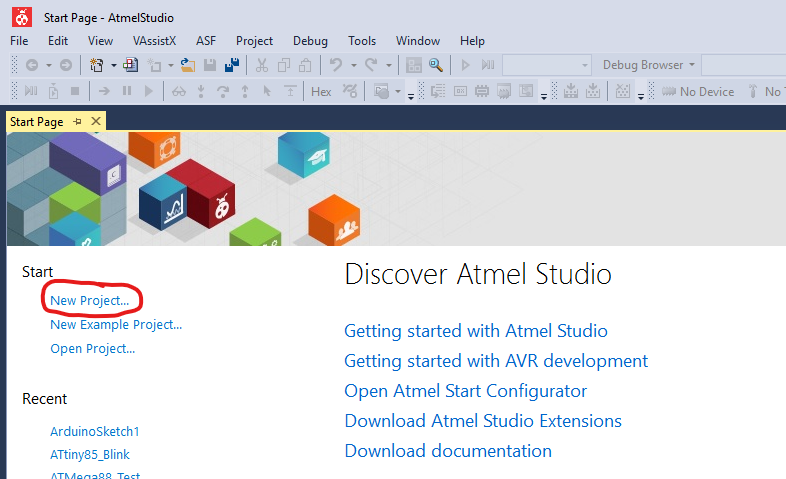
In the next step, choose “Create Project from Arduino Sketch” and give the project a name (later renaming is more complex than you might think).
Select the sketch, i.e. the “.ino” file and the board.

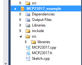
It takes a little, then the sketch is imported and appears with a few comments generated by Atmel Studio.
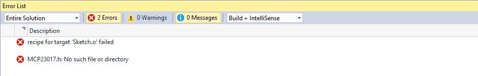
If you didn’t have to include the two libraries, you’d be ready now! Try “Build Solution”:
You will receive the following error message:

Including libraries
Include specification-compliant libraries
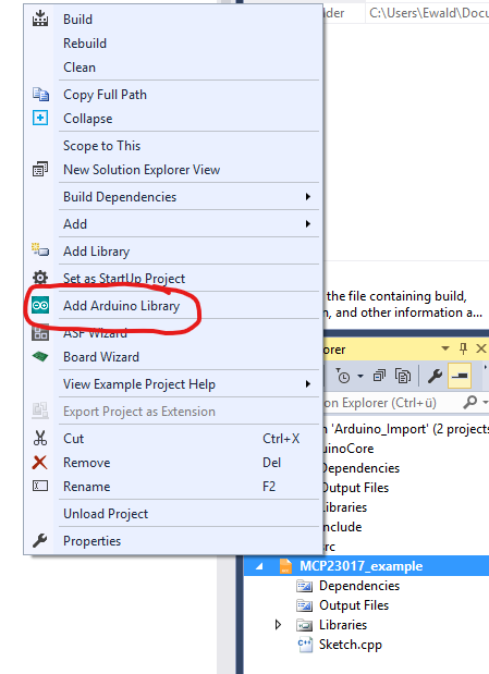
In the first step, the Wire library is integrated. To do this, you go into the Solution Explorer window and right-click on the entry that with the name of the included Arduino Sketch.

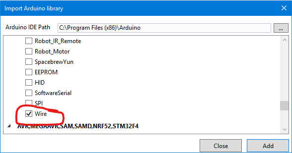
Then choose “Add Arduino Library”…
… and in the next step, tick “Wire” in the shortlist. Only the compliant libraries appear in this list.
If you go to Build Solution again, the MCP23017 library will be missed as expected.
Include non-conforming libraries
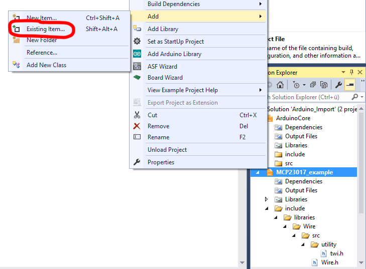
In this case, you go back to the Solution Explorer window and right-click on the entry with the Arduino sketch name. Then select “Add” and then “Existing Item…”.
Now you navigate to the directory where your library is located. Select the “.cpp” and “.h” files. If you click on the “Add” button at the bottom right, you can choose between “Add” and “Add As Link”. Both have their advantages and disadvantages. “Add As Link” is more space-saving, and you will always include the latest version of the library. But sometimes there are reasons why you might not want to do that.
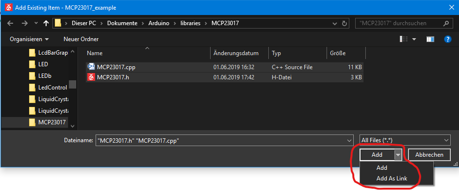
If you select “Add” then you can see the imported files in Solution Explorer, if you select “Add As Link”, then you will see the links:

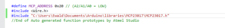
The next important measure is to replace the “< > ” brackets behind the #include command for this library with quotation marks in the program code.
If the header (“.h”) file is physically in the “src” folder, it is found by its name. If only the link has been imported, then you have to specify the path to the directory where it is actually located.

Now go again to “Build Solution” and – behold – there is no more error message.
Using debugging for the Arduino
Now you can reap the fruits of your work and use debugging for the Arduino, e.g. run the program step by step, set breakpoints, track variable and register contents, etc. Here I just want to show you how to switch to debugWire mode and set breakpoints. For the other options, look at my previous post.
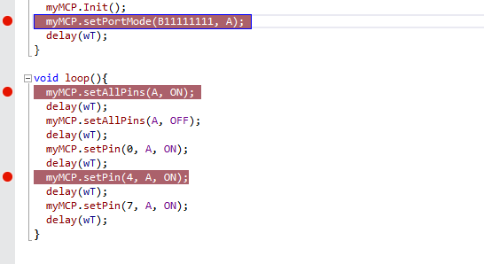
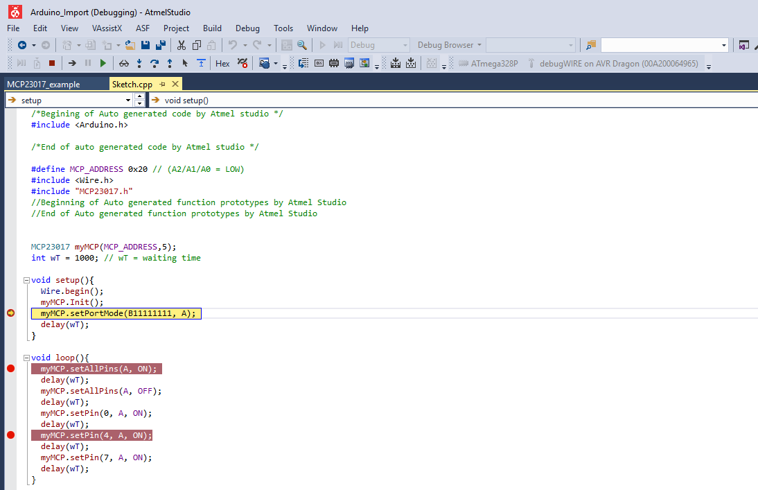
Breakpoints, i.e. points where the program stops, are simply set by clicking on the gray bar next to the program code. They appear as a red dot. Clicking on a breakpoint again deletes it. By the way, the program stops before the selected line is executed.
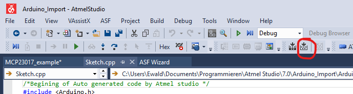
Go to Tools (the hammer icon) in the toolbar. Then choose your programmer and “debugWIRE” as interface.
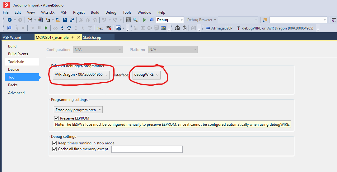
Click on “Start Debugging and Break” (the play-pause icon):

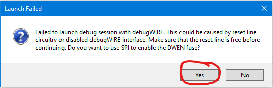
Close the following error message with “Yes”.
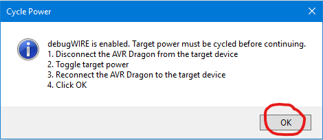
Follow the next instruction and disconnect the programmer from the Arduino, briefly interrupt the power supply from the Arduino and reconnect the programmer. I always save myself steps 1 and 3 and have never had any problems – up to you. Then click OK.
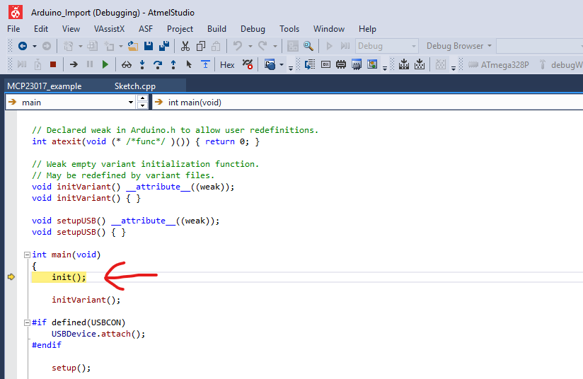
The program starts and will then stop immediately.
Now go to “Continue”…

… the program continues until the first breakpoint. With each additional “Continue” you go to the next breakpoint. In combination with tracking variable values, you have a very efficient tool for finding errors. Especially with larger sketches, the error detection can take longer than the programming work itself.
Undo debugging for the Arduino
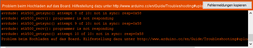
In order to be able to upload sketches to the Arduino UNO again with the Arduino IDE, further settings in the ATmega328P have to be undone before restoring the “RESET EN” contact on the Arduino board. If you do not do this, you get error messages like this when you try to upload sketches:
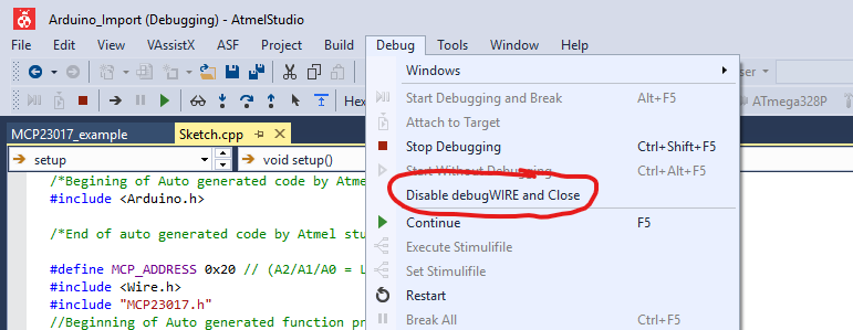
Here’s the procedure. First, stop debugWIRE mode via
Debug –> Disable debugWIRE and Close
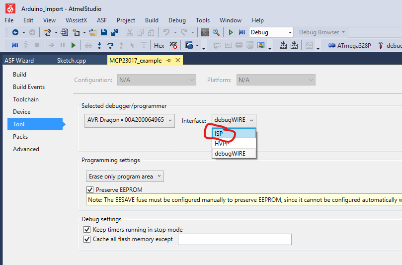
Then switch to ISP mode in the tool area:
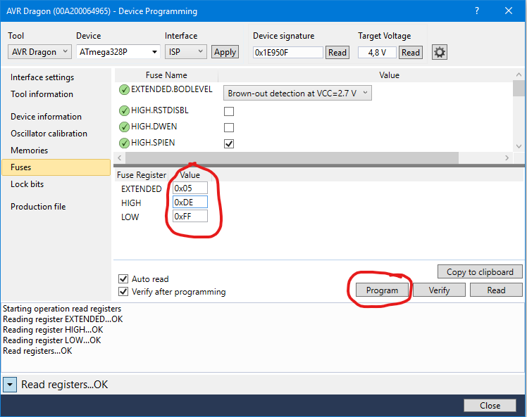
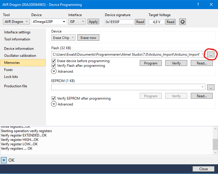
The next step is “Device Programming” (the icon with the IC and lightning). Click on “Apply”. By clicking the “Read” buttons you can query the signature of the MCU and determine the voltage at the Arduino.

Then select “Fuses” and enter the fuse register values for EXTENDED, HIGH and LOW, which are marked below. Now click on “Program”. If all goes well, you get a message “Verify Registers… OK”.
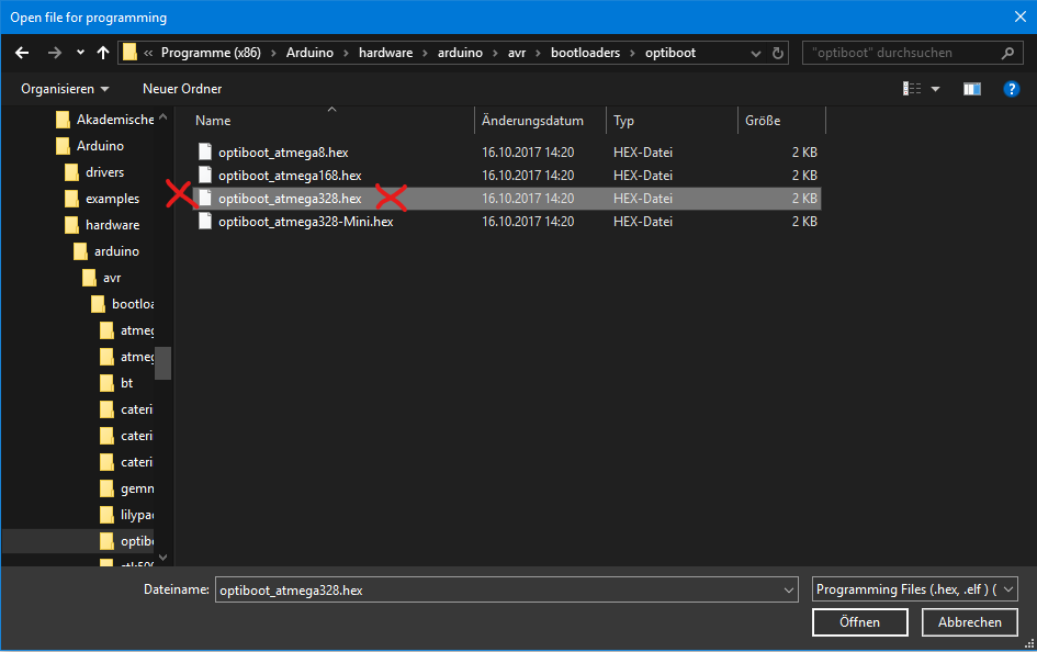
Now the Arduino bootloader has to be burned to the ATmega328P. Go to “…” (marked in red).
The correct boot loader is “optiboot_atmega328.hex”. You can find it, starting from the Arduino installation path, in hardware\Arduino\avr\bootloaders\optiboot
Now click on “Program”. Then restore the “RESET _EN” connection on the Arduino board. But let’s face it, all too often you don’t want to change back and forth. Personally, I would rather spend a few euros on a second Arduino.