
About this Post
In this article I deal with CO2 sensors for monitoring indoor air quality. Most sensors of this type work either based on metal oxides (MOx) or on infrared technology (NDIR). I will limit myself here to the latter, namely the CO2 sensors of the MH-Z series from Zhengzhou Winsen Electronics Technology.
Specifically, I will cover the following:
- The measuring principle (NDIR)
- Technical characteristics of the sensors
- Calibration
- Measured value output (analog, serial, PWM)
- Control with and without library
Finally, I check the accuracy of the sensors. For this purpose, I use a home-made CO2 measuring chamber and the Technoline WL 1030 CO2 measuring device.

At this point, I would also like to point out a good alternative to the MH-Z14 / MH-Z19 modules, namely the SCD4x modules, which I discuss here.
NDIR measuring principle of the CO2 sensors
Non-dispersive infrared sensors (NDIR) measure the CO2 content of the air via the absorption of infrared light. The fact that CO2 absorbs infrared light is something you know from the greenhouse effect. Sunlight passes relatively unhindered through the atmosphere and the CO2 it contains. The heated surface of the earth radiates the energy partly in the form of infrared light, i.e. thermal radiation. Unfortunately, this radiation is absorbed by CO2, which then leads to the warming of the atmosphere.
In the NDIR sensor there is an IR lamp and a detector. In between is the air to be measured. The more CO2 it contains, the more IR radiation is absorbed and correspondingly less arrives at the detector. “Non-dispersive” means that, unlike infrared spectroscopy, you don’t bother to split the infrared light into small wavelength ranges. A good explanation of the measuring principle can be found here.
I “dissected” an MH-Z19 (a fake model that unfortunately did not work). You can see the photos below. The white felt-like covers ensure that the air containing CO2 can enter, but the dust stays outside. So don’t remove them. Under the upper cap you find the measuring chamber. You can see the IR lamp and the sensor. The IR lamp is framed in such a way that it radiates only in one direction. The radiation is reflected by the opposite housing wall and then directed onto the detector via a mirror. Through this detour, the IR light travels a longer distance. As a result, more IR light is absorbed, leading to higher sensitivity The electronics are located under the measuring chamber.

Technical characteristics of the MH-Z CO2 sensors
The MH-Z14 sensors are much larger than the representatives of the MH-Z19 series. Otherwise, they are quite similar in terms of their technical specifications. You have to pay 20 to 30 euros for an MH-Z19, and about 10 euros more for the MH-Z14. If you are patient and can wait a bit, I recommend buying from AliExpress because it is much cheaper.
I have taken the following information from the data sheets:

At least there are data sheets, which is not always the case with Chinese modules. Oddly enough, however, they omit some relevant information. Among other things, it is not clear which measuring ranges can really be set. For example, I could only use the default range of 0 – 5000 ppm for the MH-Z14, although the data sheet tells something different. On the other hand, the adjustment of the measuring range of the MH-Z19C was no problem. And In both data sheets the serial command for setting the measuring range is not documented.
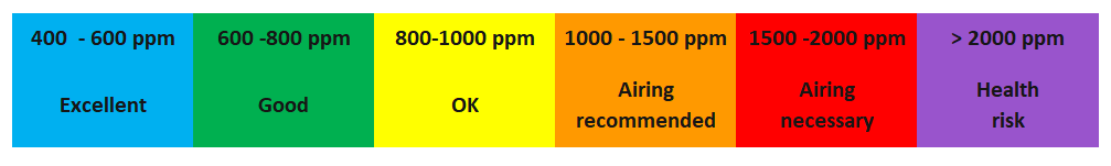
For room air monitoring, you only need the range up to 2000 ppm, as you should have ventilated the room long before. Commonly used assessments of the room air regarding the CO2 concentration are:
I found an excellent article about the MH-Z19B here. You will find more information about the selection of measured ranges, calibration methods, fake models (beware if the board is black and not green!) and other things.
Pinout
MH-Z14 – Series

The MH-Z14 sensors are not stingy with connections, but most of them are double or triple. The connection bar of the MH-Z14B looks a little different, but the labels and functions are the same. (see table).
MH-Z19 – Series

The connections within the MH-Z19 series are the same. Sometimes the analog output is not labeled.

Calibration of the MH-Zxx CO2 sensors
There are three calibration methods for the MH-Zxx sensors:
- Zero point calibration: For this, the sensor must be in a well-ventilated environment for 20 minutes. The sensor assumes that the CO2 concentration under these conditions is 400 ppm, which is roughly the current global average. There are two methods to initiate this type of calibration:
- the HD pin is connected to GND for more than 7 seconds
- via a serial instruction (we’ll get to that)
- Span Point Calibration: Calibration at a defined CO2 concentration – probably very few will be able to realize this. That’s why I don’t go into it and advise you: better not play around with it.
- Background calibration (self-calibration): The modules can calibrate themselves in 24-hour intervals (in this regard I am not sure about the MH-Z14 without suffix!). To put it simply, they consider the lowest value over the day to be 400 ppm. Of course, this only works if the device is in a room that is effectively ventilated daily. If this is not the case, then your zero point will shift. This calibration method is active by default. You can switch it off via a serial command. But then you should do a manual calibration from time to time.
An error in calibration methods 1 and 3 leads to an offset of the measured values. I will come back to that later.
Measured value output
Internally, the MH-Z sensors record a measured value every second. You can recognize this by the regular flashing. The measured values of the MH-Zxx CO2 sensors can be read in three different ways:
- Calculation from the analog voltage signal
- Via the PWM (pulse width modulation) signal
- Via serial (we come to this in serial communication)
Analog signal
The analog signal is a voltage V between 0.4 and 2.0 volts. This means that the selected measuring range is mapped in this voltage range of 1.6 volts:
![\[ \text{CO2}\;[\text{ppm}] = \frac{(V -0.4)\cdot range}{1.6} \]](https://wolles-elektronikkiste.de/wp-content/ql-cache/quicklatex.com-fcc248fc116c50d22c07270968b848cd_l3.png "Rendered by QuickLaTeX.com")
I can not recommend this method. In my experiments it showed significant deviations. With a good A/D converter like the ADS1115 it might be better.
PWM Signal
The signal on the PWM pin has a total length of 1004 milliseconds (+/- 5% according to data sheet). The higher the CO2 concentration, the longer the HIGH signal TH compared to the LOW signal TL. As a further parameter, the measuring range must be considered:
![\[ \text{CO2}\;[\text{ppm}] =\frac{T_H-2\text{ms}}{T_H+T_L-4\text{ms}}\cdot range \]](https://wolles-elektronikkiste.de/wp-content/ql-cache/quicklatex.com-f4102442c25623a483280f3ff0ae643d_l3.png "Rendered by QuickLaTeX.com")
Some examples for the measuring range 0-2000 ppm:
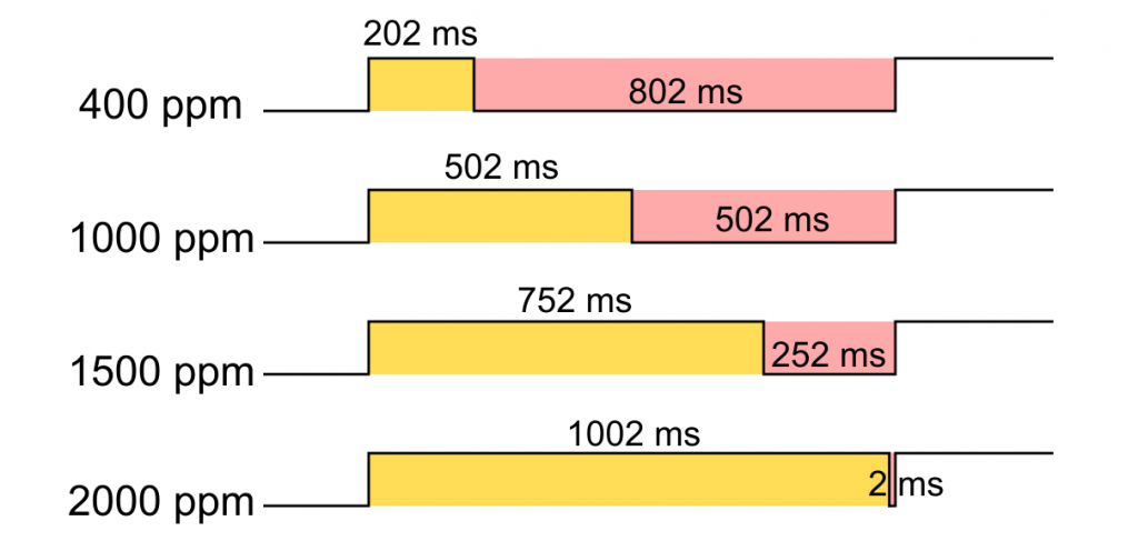
You can read the PWM signal with the pulseIn() function.
Serial communication
Serial commands and responses of the MH-Z CO2 sensors consist of nine bytes. Unfortunately, not every MH-Zxx model “understands” every command. Even more annoying is that the data sheets are not reliable in this respect. Elsewhere, I read that this depends not only on the model, but also on the firmware version.
Byte 0 is always 0xFF. Byte 8 is always the checksum calculated according to the following formula:
![\[ checksum = \text{0xFF}-\left( \sum_{i=1}^{7}{byte_i}\right) +1 \]](https://wolles-elektronikkiste.de/wp-content/ql-cache/quicklatex.com-23e625fde308b1a7f934a1a9d40a8c1a_l3.png "Rendered by QuickLaTeX.com")
Bytes 1 to 7 are added, this value is subtracted from 255 and finally 1 is added up. If the sum of the bytes is greater than 255, then the overflow is simply truncated.
For commands, byte 1 is commands 0x01. Byte 2 is actually the control byte. The value of the remaining bytes depends on the type of command and the parameters that may be passed.

For byte 6 and byte 7, the following applies to the measuring range setting:
![\[ LSB = range\; \& \; \text{0xFF} \;\;\;\; \text{und} \;\;\;\; MSB = range >> 8 \]](https://wolles-elektronikkiste.de/wp-content/ql-cache/quicklatex.com-7aeee37eaf247e11d977a7a4f5052afc_l3.png "Rendered by QuickLaTeX.com")
The byte 1 in an answer to a measured value query is the control byte 0x86. The most significant byte (MSB) of the measured value is byte 2, the least significant byte (LSB) is byte 3:
![\[ \text{CO2 [ppm]} = MSB\cdot 256 + LSB =(MSB << 8) + LSB \]](https://wolles-elektronikkiste.de/wp-content/ql-cache/quicklatex.com-985a9ba17a834c572ef94d558b80e624_l3.png "Rendered by QuickLaTeX.com")
Other serial settings
There are other undocumented commands and queries. For these, too, the applicability depends on the model and the firmware. You can find a good overview here.
How to control the CO2 sensors with a microcontroller
Wiring
The wiring is basically the same for all MH-Zxx CO2 sensors:
- VIN/GND: Connection to a stable power supply.
- RX /TX: RX to TX and TX to RX, preferably via SoftwareSerial.
- HD: if you want or need to calibrate manually, I would connect this pin to GND via a push-button or connect it to an I/O pin. OUTPUT/LOW for > 7 seconds starts the calibration.
- PWM: is hooked to any I/O pin.
- Analog Out: is connected to an analog input or A/D converter.
How to control the sensors with libraries
For the MH-Zxx CO2 sensors, a number of libraries are available. However, the selection for MH-Z14 models is smaller. I tried two libraries.
The MH-Z19 library by Jonathan Dempsey is, as the name suggests, written specifically for the MH-Z19 sensors. It works with both the B and C variants. My attempt to use it for the MH-Z14 failed. The MH-Z19 library is characterized by the fact that it uses many of the undocumented commands, such as the query of the range or the firmware version. Thanks to the many example sketches, it is easy to use. You can find the library here on GitHub or you install it directly via the library manager of the Arduino IDE.
Then I tried the library MH-Z CO2 Sensors by Tobias Schürg. It can also be found on GitHub (here)as well as in the Arduino library management. The library worked with both the MH-Z14 and the MH-Z19. However, I needed to make a small adjustment in MHZ.cpp. If this is (still) the case for you, search for the line if (!isReady()) return STATUS_NOT_READY; and comment it out. It’s line 110 in the current release. I hope the author resolves the problem. At least it is reported as an issue. For the MH-Z14 I adjusted the example sketch:
//#include <ESP8266WiFi.h>
#include <SoftwareSerial.h>
#include <MHZ.h>

// pin for pwm reading
#define CO2_IN 9

// pin for uart reading
#define MH_Z19_RX 10
#define MH_Z19_TX 11

MHZ co2(MH_Z19_RX, MH_Z19_TX, CO2_IN, MHZ14A);

void setup() {
  Serial.begin(9600);
  pinMode(CO2_IN, INPUT);
  delay(100);
  Serial.println("MHZ 14A");

  // enable debug to get addition information
  // co2.setDebug(true);

//  if (co2.isPreHeating()) {
//    Serial.print("Preheating");
//    while (co2.isPreHeating()) {
//      Serial.print(".");
//      delay(5000);
//    }
//    Serial.println();
//  }
}

void loop() {
  Serial.print("\n----- Time from start: ");
  Serial.print(millis() / 1000);
  Serial.println(" s");

  int ppm_uart = co2.readCO2UART();
  Serial.print("PPMuart: ");

  if (ppm_uart > 0) {
    Serial.print(ppm_uart);
  } else {
    Serial.print("n/a");
  }

  int ppm_pwm = co2.readCO2PWM();
  Serial.print(", PPMpwm: ");
  Serial.print(ppm_pwm);

  int temperature = co2.getLastTemperature();
  Serial.print(", Temperature: ");

  if (temperature > 0) {
    Serial.println(temperature);
  } else {
    Serial.println("n/a");
  }

  Serial.println("\n------------------------------");
  delay(5000);
}
Control without library
For the control without library I wrote a sketch myself. I successfully tested it with an MH-Z14 and an MH-Z19C. However, you must make sure that the measuring range you have selected can actually be set. You will see that a measuring range has not been set if the values you receive via PWM and the serial query are significantly different. And – as already mentioned – not all commands work with every model.
For the PWM query, I decided against the convenient pulseIn() method because it only determines the HIGH phase. HIGH and LOW phase together should be 1004 milliseconds. According to the data sheet, however, this value can vary by up to 5%. A determination of HIGH and LOW phase should compensate for this error.
I selected pins 10 and 11 for SoftwareSerial. I hooked the PWM pin to pin 9 and the HD pin for calibration to pin 8. The analog signal is read via A0.
getCO2AndTemp() gets its parameters as references and does not return a value. This is a solution to the problem that C++ cannot return two values.
The 9-byte commands are “assembled” piece wise and stored in the byte array “cmd”. The responses of the MH-Zxx sensors are stored in the byte array “message”.
Otherwise, I hope the code is reasonably understandable.
#define RANGE_2000  0x07D0
#define RANGE_5000  0x1388
#define RANGE_10000 0x2710
#define TEMP_CORR 38  // seems to differ from module to module!

#include <SoftwareSerial.h>
const int pwmPin = 9;
const int hdPin = 7;
unsigned int rangeFactor = 5000; //not every range works for every MH-Zxx!

SoftwareSerial myMHZ(10, 11); // RX, TX

void setup(){
  pinMode(hdPin, OUTPUT);
  digitalWrite(hdPin, HIGH);
  pinMode(pwmPin, INPUT);
  Serial.begin(9600);
  myMHZ.begin(9600);
  while(!Serial){}
  while(!myMHZ){}

  setRange(RANGE_2000);
  Serial.print("Range: ");
  Serial.println(getRange()); // does not work with all MH-Zxx sensors
  Serial.print("Firmware: ");
  Serial.println(getFirmwareVersion()); // does not work with all MH-Zxx sensors

  // for calibration your MH-Zxx needs to run in a 400 ppm CO2 environment for 20 min!!!
  // if the MH-Z module supports it, you can calibrate via serial commands
  // if not, choose the HD - method)
  // calibrateMHZ(); // calibration via serial command
  // calibrateMHZByHD(); // calibration via HD pin
  // activate/deacvtivate the permanent calibration which is happening in the background (if supported):
  // activateCalibrationMode(true);

  Serial.print("Self Calibration Mode: ");
  if(getSelfCalModeStatus()){ // does not work with all MH-Zxx sensors
    Serial.println("ON");
  }
  else Serial.println("OFF");
}

void loop(){
  unsigned int ppmCO2PWM = 0;
  unsigned int ppmCO2Serial = 0;
  float ppmCO2Analog = 0.0;
  int temperature = 0;

  ppmCO2PWM = getCO2PWM();
  getCO2AndTemp(ppmCO2Serial, temperature);
  ppmCO2Analog = (((analogRead(A0))/1023.0 * 5.0) - 0.4)/1.6 * rangeFactor;

  Serial.print("CO2 in ppm (PWM): ");
  Serial.println(ppmCO2PWM);
  Serial.print("CO2 in ppm (Serial): ");
  Serial.println(ppmCO2Serial);
  Serial.print("CO2 in ppm (Analog): ");
  Serial.println(ppmCO2Analog);
  Serial.print("Temperature [°C]: ");
  Serial.println(temperature);

  Serial.println("**********************");
  delay(1000);
}

void setRange(unsigned int range){
  rangeFactor = range;
  sendCommand(0x99, range);
  delay(100);
}

void calibrateMHZ(){
  sendCommand(0x87, 0x00);
}

void calibrateMHZByHD(){
  Serial.println("Calibration - please wait for initialization");
  digitalWrite(hdPin, LOW);
  delay(10000);
  digitalWrite(hdPin, HIGH);
  Serial.println("Done");
}

void activateCalibrationMode(bool activate){
  if(activate){
    sendCommand(0x7A, 0x00); // my own command for activation
  }
  else{
    sendCommand(0x79, 0x00);
  }
  delay(100);
}

unsigned int getRange(){
  byte message[9];
  getResponse(message, 0x9B);
  unsigned int range = (unsigned int)(message[4]<<8) + message[5];
  return range;
}

void getCO2AndTemp(unsigned int &ppmCO2, int &temp){
  byte message[9];
  getResponse(message, 0x86);
  ppmCO2 = (unsigned int)(message[2]<<8) + message[3];
  temp = (int)(message[4] - TEMP_CORR);
}

String getFirmwareVersion(){
  byte message[9];
  String firmware = "";
  getResponse(message,0xA0);
  for(int i=2; i<6; i++){
    firmware += (char)message[i];
  }
  return firmware;
}

byte getSelfCalModeStatus(){
  byte message[9];
  getResponse(message, 0x7D);
  return message[7];
}

void sendCommand(byte cmdByte, unsigned int range){
  byte cmd[9] = {0xFF, 0x01, 0x00, 0x00, 0x00, 0x00, 0x00, 0x00, 0x00};
  cmd[2] = cmdByte;
  if(cmdByte==0x99){
    cmd[6] = range>>8;
    cmd[7] = range & 0xFF;
  }

  if(cmdByte==0x7A){ // my own command for activation of self calibration
    cmd[2] = 0x79;
    cmd[3] = 0xA0;
  }
  cmd[8] = getCheckSum(cmd);
  myMHZ.write(cmd,9);
}

unsigned int getCO2PWM(){
  unsigned long highPeriod = 0;
  unsigned long lowPeriod = 0;
  unsigned long startTime = 0;
  unsigned int ppmCO2 = 0;

  while(digitalRead(pwmPin)){}
  while(!digitalRead(pwmPin)){}
  startTime = millis();
  while(digitalRead(pwmPin)){}
  highPeriod = millis() - startTime;
  startTime = millis();
  while(!digitalRead(pwmPin)){}
  lowPeriod = millis() - startTime;

  ppmCO2 = rangeFactor*(highPeriod - 2)/(highPeriod + lowPeriod - 4);

  return ppmCO2;
}

void getResponse(byte msg[], byte cmdByte){
  unsigned long maxWaitTime = 1000;
  while(myMHZ.available()){
    myMHZ.read();    // removes "rubbish"
  }
  sendCommand(cmdByte, 0x00);
  unsigned long startTime = millis();

  while(!myMHZ.available()){
    if((startTime-millis())>maxWaitTime){ // if the MH-Zxx does not respond
      break;
    }
  }

  myMHZ.readBytes(msg,9);
}

byte getCheckSum(byte *seq){
  byte checkSum = 0;
  for(int i=1; i<8; i++){
    checkSum += seq[i];
  }
  checkSum = 255 - checkSum + 1;
  return checkSum;
}
Accuracy of the MH-Zxx CO2 sensors

I checked the accuracy of the MH-Zxx CO2 sensors with the Technoline WL 1030, a commercially available CO2 measuring device. This model was the 2021 winner of the German test institute “Stiftung Warentest” in the category of CO2 measuring instruments. Nevertheless, the question naturally arises as to how accurately it measures itself, especially as it appears to be based on an MH-Zxx sensor or similar, if you look at how it works and the technical data.
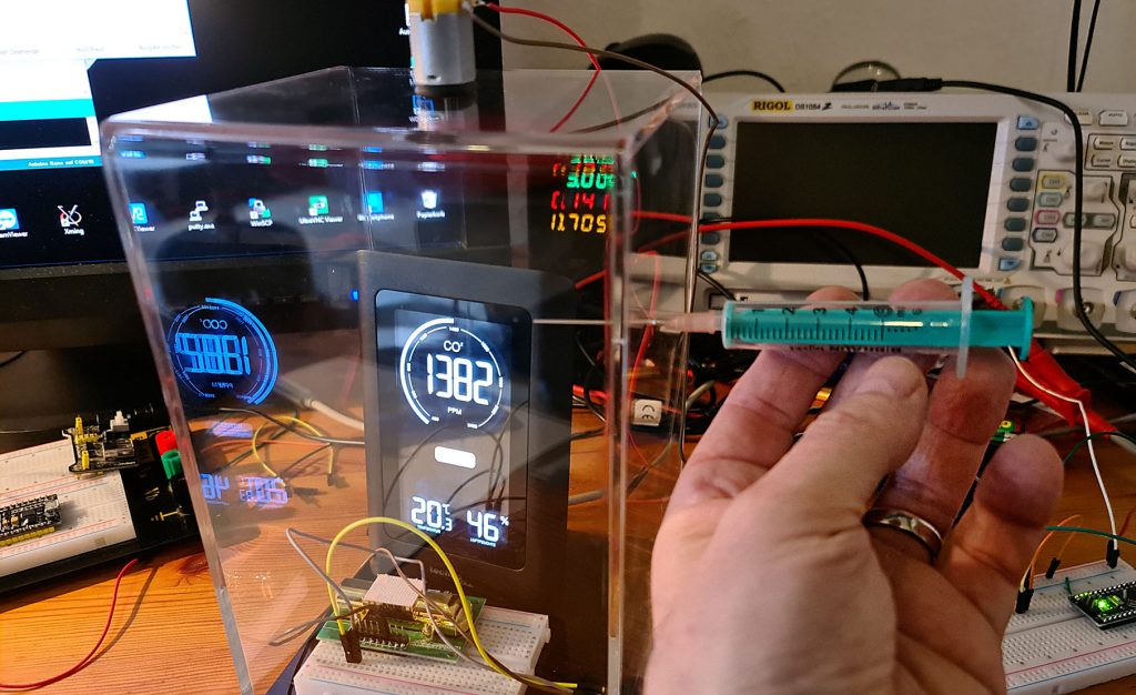
For this purpose, I have built a CO2 measuring chamber. The basis was a box made of acrylic plastic, which is usually used to exhibit things like action figures or model cars. I fed the CO2 through a small, sealable hole with a syringe. An electric motor with propeller ensured the even spread of the gas. Then I glued in a breadboard and installed access for electrical connections. I placed the Technoline WL 1030 in the chamber and drilled a hole for the power supply cable into the box. The CO2 was provided by my water carbonator.

Test of the Technoline WL 1030
The experiment
I ran the Technoline WL 1030 for several days and calibrated it according to the operating instructions. This works in principle as with the MH-Zxx CO2 sensors. Before the measurements, I aired the room well to achieve a starting value of 400 ppm.
The internal dimensions of the box are 13 cm x 13 cm x 20 cm = 3380 cm3. For the Technoline WL 1030 I estimated a volume of 260 cm3. However, it consists for the most part of “air”. In the end, I took 130 cm3 for the measuring device and the breadboard. Thus, the remaining volume in the measuring chamber is about 3250 cm3. If I am wrong by 50 cm3, that is an error of 1.5%. An addition of one milliliter of CO2 should increase the CO2 concentration by 1/3250 = approx. 308 ppm.
I fed 0.5 or 1 milliliter of CO2 at a time and waited for a reasonably stable value. This took about 5 minutes each. Since my measuring chamber is not absolutely gas-tight, the measured value slowly decreased again after reaching a maximum. In total, I fed 4 ml of CO2 into the chamber. These are the measured values:

Evaluation of results
The final value after feeding 4 ml of CO2 should have been 1632 ppm. I measured a maximum of about 1500 ppm. However, the chamber is not really gas-tight. To estimate the error, I repeated the experiment, but this time I fed 4 ml of CO2 in one step. The final value was about 1550 ppm (green rhombus). After another 5 minutes, the concentration dropped to slightly below 1500 ppm (yellow circle) due to leakage, i.e. a loss of about 50 ppm. I had waited for the first measured value for 5 minutes. Assuming a constant leak rate, I would have to add 50 ppm to the first reading. This is very close to the theoretical 1632 ppm. Admittedly, this was the best measurement. Repeat measurements showed some variation, but the results were not off by more than 5% (after correction for leakage). Outliers are of course also caused by other errors, e.g. that I may have added a little air when drawing up the syringe.
My conclusion is that you can rely on the measured values of the Technoline 1030 – careful calibration provided.
Measurements using the MH-Zxx CO2 sensors
I then took the Technoline WL 1030 to test the MH-Zxx sensors. First, a small video about it:
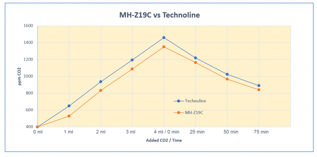
In my experiments with the MH-Zxx CO2 sensors, I found that they responded more slowly than the Technoline WL 1030. Perhaps this is simply design related, and it takes longer for the CO2 to penetrate the MH-Zxx sensors. There may also be a damping algorithm running in the background. In any case, the effect is that the measured values of the MH-Zxx sensors were still increasing, while the measured values of the Technoline WL 1030 were already decreasing. As a result, the measured values of the Technoline were somewhat higher in the addition phase. After the addition phase, the CO2 concentration slowly decreased due to the leakage of the measuring chamber. Here, too, the MH-Zxx sensors reacted more slowly and delivered correspondingly higher values. Here is an example of a result for the MH-Z14 sensor:

The results for the MH-Z19C looked very similar. Overall, I was as surprised as I was pleased with the good measurement results. However, it is also important here that the zero point calibration (more precisely the 400 ppm calibration) is carried out carefully.
And this happens with poor calibration
If you perform the calibration in a not thoroughly aired environment, you shift the 400 ppm starting point accordingly. This happened to me in the measurement shown below with an MH-Z19C. At first, I just wanted to discard the data, but then I found it quite interesting. You can see that the measured values are shifted in parallel. The incorrect calibration does not have an influence on the slope.
Conclusion
The MH-Zxx CO2 sensors provide reliable values, but you have to calibrate them correctly. Either you perform a manual calibration from time to time or you use the automatic calibration. For the latter, however, you have to make sure that the sensor is in a room that is regularly ventilated. Under no circumstances are the MH-Zxx sensors suitable for quickly switching them on to carry out ad hoc CO2 measurements.
Acknowledgement
I found the post picture on Pixabay. It comes from Malte Reimold. I just cropped it square.
Thanks Wolfgang, super helpful !
I just have one question – you refer to the following article https://unsinnsbasis.de/co2-sensor-mhz19b/ which unfortunately is not accessible anymore. Would you be able to point to an alternative address ?
Thanks
What a shame! This article was good. Unfortunately, it seems the website has not moved, but it just disappeared 😔. If I knew before, I would have asked if I could just copy the content. This is the disadvantage of the nice digital world.
There is often a way back 🙂
http://web.archive.org/web/20230324092606/https://unsinnsbasis.de/co2-sensor-mhz19b/
https://web.archive.org/
Best reradgs Peter
Hi Peter, cool – thank you!!!
The best explanation I found to correctly use the MH-Z19 sensor. Very good job, thank you very much for sharing it
This is very kind and motivating for me – thank you.
Hello, sorry for bothering. I would like to ask about the zero point calibration, I just want to make sure some stuff.
1. Do I need to put all the pin normally first and put the sensor on open environment for at least 20 minutes before calibrating (Wait until its around 400 ppm)?
2. Do I still connect the V+ to 5V/VCC and the PWM Pin to Arduino if I want to start the calibration?
3. Does it mean that I connect the HD Pin (From MH-Z14 Board) to
GND (From MH-Z14 Board)
or
GND (From Arduino Board)?
Thank you very much!
Hi,
no problem. I also learn from questions. E.g. where to be maybe more precise in future.
To your questions:
1) The MH-Z14 needs to be connected to the power supply and the HD pin should be connected to HIGH level. The electronic inside needs that time to stabilize.
2) To start the calibration you only need to keep it power-supplied and the HD Pin must be set to GND for some seconds. The other connections are not important.
3) It is sufficient to connect the HD Pin to the GND of the MH-Z14 if no Arduino is connected. And if you connect an Arduino then you also have to connect the GND of the Arduino with GND of the MH-Z14. If they don’t have the same GND, the communication between the devices won’t work.
Good luck!
Thanks, man this is an excellent explanation.
Thank you!!
Thanks, you did a great job. Does the MH-Z14A hold its calibration after a power cycle?
Unfotunately it seems to forget its calbration. The data sheet (if you can call this a data sheet) is not very clear. If you dis- and reconnect to power then I would start in 400 ppm CO2 environment and do a zero point calibration.
I just made my own CO2 meter with an MH-Z14A and an ESP32 TTGO with small OLED display. After power on it starts with 410 ppm and then after a minute it goes back to the real value (same as before the power reset). I’m very pleased with the result.
Great, happy to that your project works fine!
Seht beeindrückt
grosse Arbeit
Danke