
About the post
A lot has been written already about Bluetooth, Arduino and the HC-05 and HC-06 Bluetooth modules. Nevertheless, it took me quite a lot of time to fully cope with these devices, since the information I needed was spread on many websites and posts. Here is an attempt to unite everything in one place. I will cover the following topics in this post:
- Bluetooth vs. 433 MHz radio
- common Bluetooth modules
- Circuit diagrams for controlling the modules
- Setting up the Bluetooth modules using AT commands via:
- Arduino IDE
- Putty
- DSD Tech Tool
- pairing Bluetooth modules with each other
- power consumption and range
I will explain in a separate post how to connect the Bluetooth modules to a smartphone because of the size of this topic.
Bluetooth vs. 433 MHz radio
There are a number of different techniques for wireless transmission. In addition to Bluetooth, Wi-Fi, infrared and (433 MHz) radio technology are the most suitable. For the communication from Arduino to Arduino, one will most likely use the 433 MHz technology or Bluetooth. The 433 MHz technology has the advantage of a higher range and the modules are slightly cheaper. There is also Bluetooth technology with a higher range available, but the standard modules are designed for distances of 10 or maximum 20 meters. In my view, the advantages of Bluetooth technology are the exclusive connections (i.e. you can limit the pairing to a specific module) and, above all, the possibility to communicate with smartphones. If you want to get more into the details of Bluetooth technology, you can do so e.g. on Wikipedia.
Common Bluetooth Modules
The HC-05 and HC-06 Bluetooth modules are most established ones in the world of microcontrollers. They are available for about 8 euros from Amazon or online electronics shops. In addition to HC-05 and HC-06, you might come across hc-08 and HM-10 modules. The latter are also suitable for IOS operating systems. The HC-08 modules, which I once bought, I could program via AT commands, but I could not pair them neither with my Android smartphone nor with each other. In this respect, in my experience, I cannot recommend these parts.
The HC-05 and HC-06 Bluetooth modules discussed here (see picture below) are basically modules of modules. The respective “daughter module” is the green part attached to the blue “mother module”. If you search for data sheets for HC-05 and HC-06 Bluetooth modules, they usually refer to the “daughter modules”. The “mother modules” save a lot of cabling work, but also reduce flexibility.

Programming HC-05 and HC-06 Bluetooth modules
The circuit
Before you can use HC-05 and HC-06 Bluetooth modules for communication, you may need to adjust some settings using the so-called “AT commands”. There are different methods for this. First, I would like to show how to do this by means of Arduino.3.3 Volt limitation of the RX pin
The HC-05 and HC-06 Bluetooth modules communicate via their serial RX and TX pins. The power supply of the modules is 3.6 to 6 volts. The RX-Pin, on the other hand, is actually only designed for 3.3 volts. In my circuit below, I solved this issue with a voltage divider. Alternatively, you can also take a level converter (available for < 1 Euro). Or you use an Arduino Due or work with the “naked” microcontrollers and run everything with 3.3 volts (but you still need > 3.6V at VCC). But honestly, normally I just ignore the demand and work with 5 volts. And I haven’t broken a module yet.The circuit is identical for the HC-05 and HC-06 Bluetooth modules. The “State” and “Enable” pins on the HC -05 remain unconnected. As an example, I used an Arduino Nano. Pin 10 and pin 11 of the Arduino are set as RX and TX respectively by software serial.

Setting the HC-06 module using AT commands
Preparation
I start with the HC-06, as it is slightly easier to handle than the HC-05 module. First, the following sketch is uploaded to the Arduino.
#include <SoftwareSerial.h>
SoftwareSerial mySerial(10, 11);

void setup() {
  Serial.begin(9600);
  Serial.println("Los geht's");
  mySerial.begin(9600); //38400 für hc-05
}

void loop() { // run over and over
  if (mySerial.available()) {
    Serial.write(mySerial.read());
  }
  if (Serial.available()) {
    mySerial.write(Serial.read());
  }
}
Now at the latest the HC-06 module is connected to the Arduino according to the circuit shown above. When the module is powered, a red LED should flash quite frantically (multiple times per second). There are also versions that also have a blue LED (e.g. hc01.comV2.0) and those without (e.g. linvorV1.8).
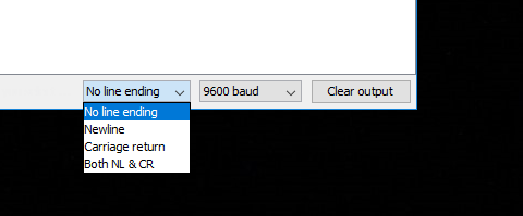
Then you can use the serial monitor to adjust the settings of the modules using AT commands. It is important that the baud rate is 9600 and “No line end” is set on the serial monitor. It should also be noted that the HC-06 module is not responsive to AT commands when paired, i.e. if there is a Bluetooth connection.
AT commands for the HC-06
As a first test you can send a simple “AT” toi the module. In response, you get a friendly “OK”. If you send more “AT” commands, you can see that all responses appear without spaces or line feeds.
Then you might want to change the name of the module. If, for example, it is called Karl-Heinz, you send a
AT+NAMEKarl-Heinz — > answer: OKsetname
For the change of the pin, you send
AT+PIN<your 4-digit PIN> — > answer: OKsetPIN
The default is a baud rate (data transfer rate) of 9600. If you want to change this, you can do so using the following key:

To set a baud rate of, for example, 9600, the command is:
AT+BAUD4 — > answer: OK9600
But be CAREFUL- it could happen that you can’t change back if you choose a baud rate being too high. For example, a PC can only deliver a baud rate of up to 115200. If you set a higher baud rate to HC-06, you can no longer tell the module that you want a lower rate. There is also no hardware reset. The HC-05 module can do this better.
An important setting is the role of the module, namely either master (“M”) or slave (“S”). Here is the setting as a slave:
AT+ROLE=S — > answer: OK+ROLE:S
If you want to activate or deactivate the blue LED, you can do so via the following command:
AT+LED1 –> answer: LED ON / AT+LED0 –> answer: LED OFF
The version of your HC-06 module can be queried with the command:
AT+VERSION — > response: hc01.comV2.0 (example)
Finally, even if most people won’t need it, you can set the parity bit. This is either “N” for no check, “O” for ODD or “E” for EVEN, for example:
AT+PN — > answer: OK None
Setting the HC-05 module using AT commands
Preparation
The HC-05 module is connected to the Arduino according to the circuit shown above. The sketch for communication by means of AT commands has to be slightly adjusted, because the HC-05 in AT mode always uses a baud rate of 38400. Accordingly, in line 7 “9600” has to be replaced by “38400”. The advantage of the HC-06 is that you can’t exclude yourself by an unfortunate baud rate choice. Another difference is that the HC-05 must first be brought from pairing mode to AT mode by disconnecting the power supply and pressing the small button right above the pins while restoring the power supply. Then you can release the button. The successful change to AT mode can be recognized by the fact that the frantic flashing of the red LED turns into a slow flashing (every 2 seconds).
Second AT mode
Unfortunately, however, things are a little more complicated, as there are two AT modes. There are AT commands that can only be executed in the second mode. This includes, for example, the command for querying the name. The second mode is achieved by holding the button permanently down – which is of course somehow unwieldy. Alternatively, you apply a HIGH level to the PIN 34 of the daughter module. For this you can solder a cable (see below) or you can use a mini clamp.
I also have HC-05 modules where you go into the second AT mode if you set the pin “EN” to HIGH. For other HC-05 modules, however, this is of no use. There, in turn, the pin “EN” can be used to turn off the module by setting it to “LOW”. Pretty mess – I can’t do anything about it! Try it out with your modules. The good news is that you don’t usually miss the commands from the second AT mode. For example, you can change the name of the module in the first mode, you just can’t query it.

Implementation
If you have wired everything, uploaded the sketch and put the HC-05 into AT mode, you can program it with AT commands via the serial monitor. The baud rate is set to 9600 (not 38400!) and “Both NL & CR”. For testing purposes, you can send “AT” again and get a friendly “OK” in response. Unlike the HC-06, each response is printed in a new line. In addition, the command set is larger, the spelling is slightly different, and the HC-05 is more “talkative”. You can also query all settings. A certain convenience is also the error codes, which are reported in case of incorrect entries. A list of error codes can be found below.
AT commands for the HC-05 module
Let’s get to the most important AT commands. The pin is called Password here and is set as follows:
AT+PSWD=<deine 4stellige PIN> — > answer: OK
Since the answer is always OK except for queries, I will omit this information from now on. The pin is queried as follows:
AT+PSWD? — > answer: +PSWD: < your 4 digit pin>
The role (master=1 or slave=0 or slave loop=2) of the module is set this way:
AT+ROLE=<0, 1 oder 2> –> query: AT+ROLE?
In slave loop mode, all data received via Bluetooth is sent back again.
The baud rate is set together with the parity bit and the stop bit, which I both recommend to keep as “0”. The command for a baud rate of 38400 looks like this:
AT+UART=38400,0,0 –> query: AT+UART?
The HC-05 has different connection Modes (CMODEs). In CMODE 0 (default), the module only pairs with the Bluetooth device which has the BIND Bluetooth address (explanation follows). In CMODE 1, on the other hand, the HC-05 pairs with any available device, provided (among other things) the HC-05 is set as the master and the partner device as a slave.
AT+CMODE=<0 oder 1> –> query: AT+CMODE?
For example, if the BIND address is 12:23:34:45:56:67 or 1223:34:4556 in the NAP:UAP:LAP spelling (non-significant, upper, lower address part), you will receive:
AT+BIND? –> answer: +BIND:1223:34:455667
The BIND address can be set as follows:
AT+BIND=1223,34,455667
Your own address is queried with:
AT+ADDR?
Finally, a very useful command, namely for resetting the module to factory settings:
AT+ORGL
More AT commands and error codes can be found here:
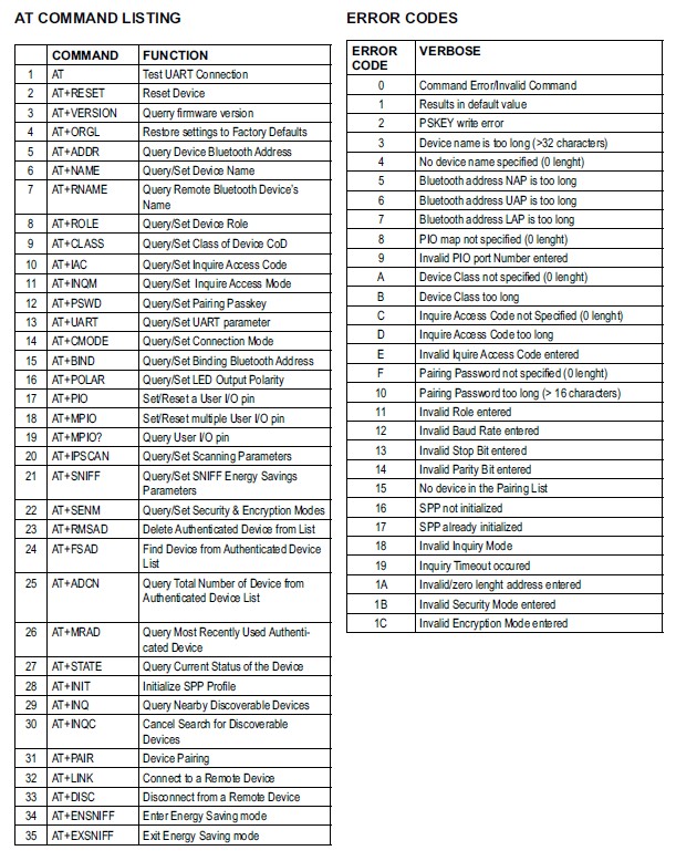
And a good description of the commands can be found here.
Alternative methods for setting the HC-05 and HC-06 Bluetooth modules
Using Arduino and without SoftwareSerial sketch
To do this, upload the BareMinimum Sketch from the examples and connect RX of the module to RX (pin 0) of the Arduino, TX of the module to TX (pin 1) of the Arduino. In the serial monitor for the HC-06 the set baud rate is to be selected, in the case of the HC-05 it’s always the baud rate 38400. The HC-05 is of course also to be brought into AT mode here. I will stop pointing this out all the time.
Without Arduino, with Arduino IDE and USB-to-TTL adapter
USB-to-TTL adapters are available for a few euros. If you take a model which adjust the voltage to 3.3 volts, you no longer need a voltage divider or similar at the RX input.

Here the cabling is again crosswise, i.e. RX on TX and TX on RX. Then connect the adapter to the PC and select the appropriate port in the Arduino IDE. Set the right baud rate and the right line settings and that’s it. You don’t need a sketch.
Using a USB-to-TTL adapter and Putty
If you use the popular Putty terminal software you must first apply the correct settings.


When using the HC-05, the response is sent permanently, which can be stopped with an “Enter”.
There are, of course, many other similar programs like Putty. For example, I tried USR-TCP232 and it also worked fine.
Using an USB-to-TTL adapter and the DSD TECH tool
With the DSD-TECH tool only a few settings can be made, but you don’t have to deal with AT commands.

Pairing HC-05 and HC-06 Bluetooth modules with each other
In the last big section I want to show how to pair the Bluetooth modules with each other to let two Arduinos communicate with each other, for example. In the following experiments I controlled one module with an Arduino UNO and the other with an Arduino Nano. The circuit is basically the same as the one shown above.
Even more interesting is that you can also use Bluetooth to communicate between Arduinos and smartphones. But since this would be to long for this post (which is already quite big), I keep this for a separate post.
Pairing HC-06 modules with HC-06 modules.
Pairing HC-06 modules is very easy. You only have to set one module as a master and the other as a slave and both modules must have the same PIN. And both modules must of course have set the same baud rate. After you have made the settings, you may have to disconnect the modules from power and reconnect. But then they should pair within a few seconds, which can be seen by the fact that the red and blue LED (if the latter is present) on the modules light up continuously.
“Ping-Pong” test sketch
With the following sketch you can test the connection and play “Ping-Pong”. In the setup, a greeting is sent. Depending on which Arduino was first started, one greeting goes into Nirvana, the other one is received from the other side. This is the version for the UNO. On the Nano you then upload a version containing a greeting to the UNO. And then it goes back and forth. When a message is received, it is output to the serial monitor and the receiving board send its own greeting message.#include <SoftwareSerial.h>
SoftwareSerial hc_06(10, 11);
String sendMsg = "Hallo HC-06 am Nano";
String receiveMsg = "";
void setup() {
Serial.begin(9600);
Serial.println("Los geht's");
hc_06.begin(9600);
hc_06.print(sendMsg);
}
void loop() {
if (hc_06.available()) {
receiveMsg = hc_06.readString();
Serial.println(receiveMsg);
delay(1000);
hc_06.print(sendMsg);
}
}

Pairing HC-05 modules with HC-05 modules
Pairing two HC-05 modules is a bit more complicated as there are different options. Both modules must of course have the same baud rate. In addition, both modules should have the same PIN (here: PSWD). Occasionally the pairing worked without the same PIN, but I can’t say with certainty which rules this followed. The settings are made in AT mode, the pairing takes place in the pairing mode. When you power the module, you are automatically in pairing mode.
Pairing in connection mode 1
HC-05 module No. 1:
- CMODE: does not matter, ROLE=0 (Slave), PSWD same as for module No. 2
HC-05 module No. 2:
- CMODE: 1, ROLE=1 (Master), PSWD as for module No. 1
Once you have selected these settings and put both modules into pairing mode, the LEDs of both modules should flash in the same way after a few seconds. It’s a short double flash about every two seconds. Then you can test the connection with the above sketch.
Pairing in connection mode 0
HC-05 module No. 1:
- CMODE: does not matter, ROLE=0 (Slave), PSWD same as for module No. 2
HC-05 module No. 2:
- CMODE: 0, ROLE=1 (Master), PSWD same as module No. 1
In connection mode 0, the master module must have the same BIND address as the slave module. There are two ways to do this.
- You read the address of the slave module and enter it in the master module (as described above).
- The modules are initially paired in connection mode 1. This automatically registers the correct BIND address, because this is automatically the last connected address. Then you switch to connection mode 0 in the master module and “freeze” the BIND address, so to speak.
The connection mode 0 ensures that the master module only connects to a specific module.
Pairing HC-05 modules with HC-06 modules
Thank God, this is easy again. You just have to be very careful that you don’t get confused with the different AT commands, baud rates (they have to be harmonized, of course), etc.
HC-06 module:
- ROLE=S (slave), PIN like PSWD of the HC-05 module
- CMODE: 1, ROLE=1 (Master), PSWD as module No. 1
Hello, I hope you are doing well. I am trying to make a remote control car or drone using esp8266 or 32 & nrf24L01. and transmitting it to Arduino Uni with nrf24L01. I am having difficulty in making one. Please make a blog for using the required library for esp . That would be helpful. Thank you
Hello, I am always happy for recommendations for new posts – so thank you for that. But I won’t promise anything regarding timelines. And since I assume you do not want to wait for months I recommend this article:
https://howtomechatronics.com/tutorials/arduino/arduino-wireless-communication-nrf24l01-tutorial/
Regards, Wolfgang