About this post
In this sequel of my last post, I will cover pin change interrupts. AVR microcontrollers and Arduino boards based on them are relatively sparsely equipped with those external interrupts that you can set up via attachInterrupt(). The good news, however, is that pin change interrupts are available to you on all I/O pins instead. They are not quite as convenient and also a bit more difficult to configure, since you have to deal with the registers of the underlying microcontrollers. But don’t worry, it’s not rocket science, either.
I will explain the use of pin change interrupts in detail on the ATmega328P (Arduino UNO, Nano, Pro Mini) and then show on the example of the ATtiny85 that the systematics behind it is very similar on all AVR microcontrollers.
These are the topics I will discuss:
- A look inside the ATmega328P
- Practical examples for the ATmega328P
- Pin change interrupts on other AVR microcontrollers
- Pin Change Interrupts on MiniEVB Boards
A look inside the ATmega328P
Ports, Pins and PCINT
The I/O pins of the ATmega328P are arranged in the three ports PORTB, PORTC and PORTD, each comprising up to 8 pins. The pins are named accordingly: PB[7:0], PC[6:0], PD[7:0]. Here the notation “PB[7:0]” means: PB7, PB6, PB5 … PB1, PB0. Each pin has a unique pin change interrupt number, namely PCINT[23:0].

Pin Change Interrupts using the ATmega328P – the relevant registers
Only one pin change interrupt is available for each port, but it can be triggered on any individual pin of the port, provided the pin has been set up for this purpose. To enable a pin for change interrupts, set the associated bit in the relevant pin change mask register PCMSK[2:0]. Here is an overview:
![Pin Change Interrupt Mask Register PCMSK[0:2]](https://wolles-elektronikkiste.de/wp-content/uploads/2023/09/pcmsk_registers-1-1024x244.png)
Furthermore, you have to activate the interrupt itself. This is done by setting the associated Pin Change Enable Bit PCIE[2:0] in the Pin Change Interrupt Control Register PCICR.

PCIE0 is responsible for PORTB, PCIE1 for PORTC and PCIE2 for PORTD.
In case of an interrupt, the corresponding flag PCIF[2:0] is set in the Pin Change Interrupt Flag Register PCIFR:

Practical examples for the ATmega328P
A single pin change interrupt pin
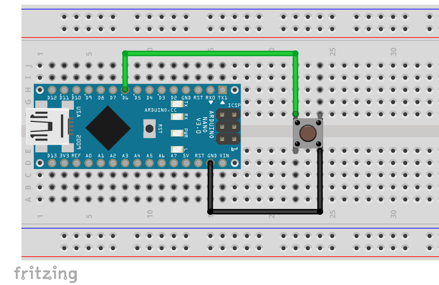
In the first example, we set up only a single interrupt pin. We choose Arduino pin 6 (PD6 / PCINT22), whose level is to change from HIGH to LOW when the button is pressed. For this purpose, we use the internal pull-up resistor. As a result of pressing the button, the board LED should light up for half a second.
Here is the example sketch for it:
const int ledPin = 13;  // = LED_BUILTIN
const int interruptPin = 6;
volatile bool event = false;

ISR (PCINT2_vect){ // PCINT2_vect: interrupt vector for PORTD
  event = true;
}

void setup() {
    pinMode(interruptPin, INPUT_PULLUP);
    PCICR = (1<<PCIE2);    // enable PCINT[23:16] interrupts
    PCMSK2 = (1<<PCINT22); // D6 = PCINT22
}

void loop() {
    if(event){
        digitalWrite(ledPin, HIGH);
        delay(500);
        digitalWrite(ledPin, LOW);
        event = false;
    }
}
Explanation to the sketch:
- With
PCICR = (1<<PCIE2)pin change interrupts at PORTD are allowed. PCMSK2 = (1<<PCINT22)enables the pin change interrupt at PD6 (= Arduino pin 6).- We pass the associated interrupt vector
PCINT2_vectto the ISR. As most people probably already guessed correctly,PCINT1_vectwould be the relevant vector for PORTC andPCINT0_vectthe vector for PORTB.
In this first, minimalistic example, no distinction is made between level changes from HIGH to LOW and from LOW to HIGH. If you press the button down for longer than 500 milliseconds, the LED will light up again when you release it.
Bouncing is not perceptible with this setting. Since I already went into detail about bouncing and debouncing in my last post, I won’t repeat that here.
And if you still need to catch up on the topic of binary operations (e.g. 1<<PCIE2) you could take a look at this article.
Multiple pin change interrupt pins on different ports
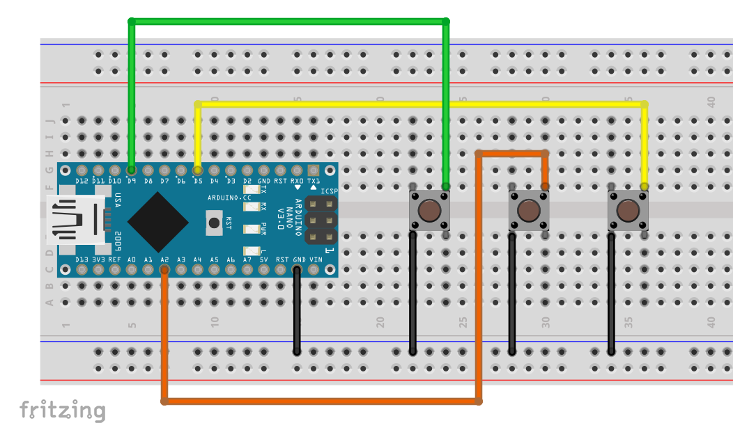
In the next step, we will monitor the level of three pushbuttons. This time we output on the serial monitor when an interrupt was triggered and at which pin it happened. For this, we use three pins from different ports:
- PB1 = Arduino Pin 9 = PCINT1
- PC2 = Arduino Pin A2 = PCINT10
- PD5 = Arduino Pin 5 = PCINT21
This is the circuit:
And here is the corresponding sketch:
const int interruptPin_1 = 9; //PB1
const int interruptPin_2 = A2; //PC2
const int interruptPin_3 = 5; //PD5
volatile bool event_1 = false;
volatile bool event_2 = false;
volatile bool event_3 = false;

ISR (PCINT0_vect){
    event_1 = true;
}

ISR (PCINT1_vect){
    event_2 = true;
}

ISR (PCINT2_vect){
    event_3 = true;
}


void setup() {
    Serial.begin(115200);
    pinMode(interruptPin_1, INPUT_PULLUP);
    pinMode(interruptPin_2, INPUT_PULLUP);
    pinMode(interruptPin_3, INPUT_PULLUP);
    PCICR = (1<<PCIE2) | (1<<PCIE1) | (1<<PCIE0);
    PCMSK0 = (1<<PCINT1);
    PCMSK1 = (1<<PCINT10);
    PCMSK2 = (1<<PCINT21);
}

void loop() {
    if(event_1){
        Serial.println("Interrupt at pin 9");
        delay(300);
        event_1 = false;
    }
    if(event_2){
        Serial.println("Interrupt at pin A2");
        delay(300);
        event_2 = false;
    }
    if(event_3){
        Serial.println("Interrupt at pin 5");
        delay(300);
        event_3 = false;
    }
}
Explanations to three_pcint_interrupts_at_three_ports.ino
- With
PCICR = (1<<PCIE2) | (1<<PCIE1) | (1<<PCIE0);interrupts are allowed at PORTB, PORTC and PORTD. - The three pins are set up as interrupt pins in their associated PCMSK[2:0] register.
- For each pin change interrupt pin, we have a separate ISR.
- The 300-millisecond delays conceal the bouncing and the additional interrupt when the button is released.
Multiple pin change interrupt pins on one port
In the next example we use pin change interrupts for three pushbuttons connected to pins 5, 6 and 7, i.e. PCINT21, PCINT22 and PCINT23. Now we have to consider that all three pins belong to PORTD and therefore only one interrupt is available. But since we know the levels of the pins in the ground state, we simply check in the ISR which pin is deviating using digitalRead() and thus is “the culprit”.
To add a little variety, we pull pin 5 and pin 7 to LOW with pull-down resistors. Pin 6 uses the internal pull-up resistor.
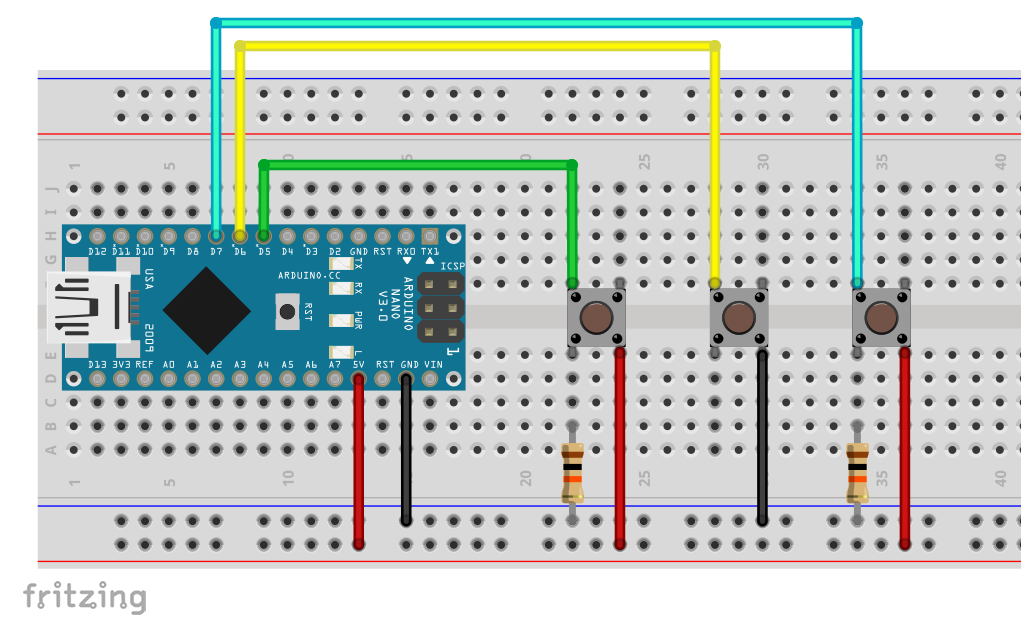
Please note, that the connections located on the top left and bottom left or top right and bottom right of the pushbuttons are connected permanently.
This is the sketch:
const int interruptPin_1 = 5;
const int interruptPin_2 = 6;
const int interruptPin_3 = 7;
volatile bool event_1 = false;
volatile bool event_2 = false;
volatile bool event_3 = false;

ISR (PCINT2_vect){
    if(digitalRead(interruptPin_1)){
        event_1 = true;
    }
    else if(!digitalRead(interruptPin_2)){
        event_2 = true;
    }
    else if(digitalRead(interruptPin_3)){
        event_3 = true;
    }
}

void setup() {
    Serial.begin(115200);
    pinMode(interruptPin_1, INPUT);
    pinMode(interruptPin_2, INPUT_PULLUP);
    pinMode(interruptPin_3, INPUT);
    PCICR = (1<<PCIE2);
    PCMSK2 = (1<<PCINT23)|(1<<PCINT22)|(1<<PCINT21);
}

void loop() {
    if(event_1){
        Serial.println("Interrupt at pin 5");
        delay(300);
        event_1 = false;
    }
    if(event_2){
        Serial.println("Interrupt at pin 6");
        delay(300);
        event_2 = false;
    }
    if(event_3){
        Serial.println("Interrupt at pin 7");
        delay(300);
        event_3 = false;
    }
}
By checking the pin level using digitalRead(), the interrupts triggered by releasing the pushbuttons are ignored (unless the pushbutton jumps when released). This may be desirable – or not. In the next but one example, I will come back to how you can detect pin changes in both directions when using one port.
Using an entire port
Now we will use (almost) the entire PORTD. This includes Arduino pins 0 to 7. Pins 0 and 1 are not suitable for pin change interrupts because they are RX and TX. We therefore restrict the interrupts to pins 2 to 7 or PD[7:2].
The following circuit is used for this purpose:
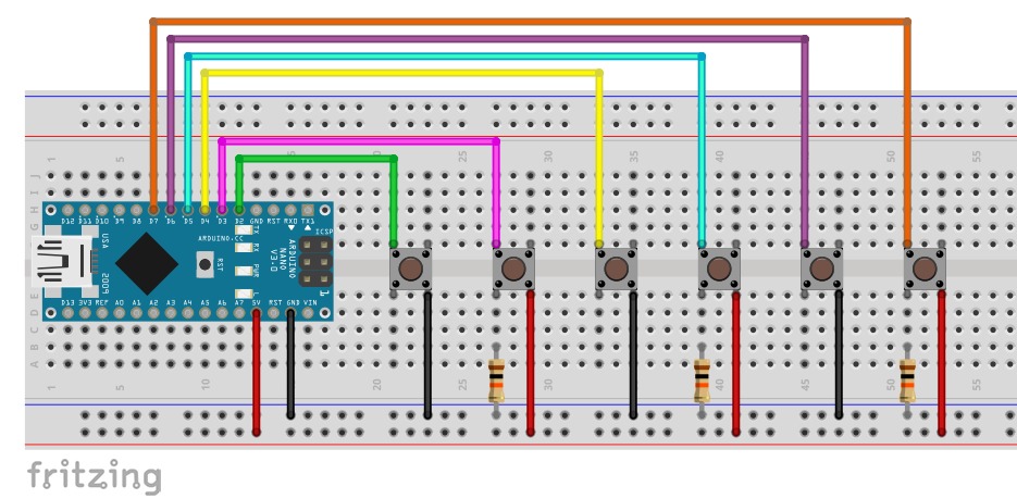
I have added pull-down resistors to pins 3, 5, and 7, and pins 2, 4, and 6 are pulled HIGH with their internal pull-up resistors. If you just want to evaluate buttons, then it would be much easier to pull all pins to the same level. However, the buttons used here are only meant to be representative of any interrupt triggers, and this could be a mixture of LOW-active and HIGH-active ones.
With six pins, it would be a bit unwieldy to query all pin states in case of an interrupt with digitalRead() and to use individual flags event_[1:6]. This can be solved in a smarter way – like this, for example:
int interruptPin[6] = {2,3,4,5,6,7};
volatile bool event = false;
volatile byte changedPin = 0;
volatile unsigned long lastInterrupt = 0;
const byte interruptPinMask = 0b11111100;
const byte intPinPolarityMask = 0b01010100;

ISR (PCINT2_vect){
    if(millis()-lastInterrupt > 300){
        byte interruptPinsStatus = PIND & interruptPinMask;
        interruptPinsStatus ^= intPinPolarityMask;
        if(interruptPinsStatus){
            changedPin = log(interruptPinsStatus)/log(2); // short, but slow! Alternative below:
//            changedPin = 0;
//            while(!(interruptPinsStatus & 1)){
//                changedPin++;
//                interruptPinsStatus = (interruptPinsStatus >> 1);
//            }
            event = true;
        }
        lastInterrupt = millis();
    }
}

void setup() {
    Serial.begin(115200);

    pinMode(interruptPin[0], INPUT_PULLUP);
    pinMode(interruptPin[1], INPUT);
    pinMode(interruptPin[2], INPUT_PULLUP);
    pinMode(interruptPin[3], INPUT);
    pinMode(interruptPin[4], INPUT_PULLUP);
    pinMode(interruptPin[5], INPUT);

    PCICR = (1<<PCIE2);
    PCMSK2 = interruptPinMask;
}

void loop() {
    if(event){
        Serial.print("Interrupt at pin ");
        Serial.println(changedPin);
        event = false;
    }
}
Explanation of pcint_interrupt_generalized.ino
- The interrupt pins are defined as an array.
- The
interruptPinMaskindicates which PORTD pins serve as interrupt pins (“1”) and which are ignored (“0”). intPinPolarityMaskcontains the default level of the PORTD pins (button not pressed).- In case of an interrupt, the current level of the pins is determined with PIND. This replaces all queries using
digitalRead().- By
PIND & interruptPinMaskwe ignore the state of pins 0 and 1. - By
interruptPinsStatus ^= intPinPolarityMaskwe find out which pin deviates from the default state. The logical operator “^” (XOR, exclusive OR) returns 1 if exactly one of the operands is 1.- For example, if the interrupt was triggered at PD4 (4),
interruptPinsStatuswould be 0b00010000 after the bit operations.
- For example, if the interrupt was triggered at PD4 (4),
- By
- The condition
if(interruptPinsStatus){...catches cases where no triggering interrupt pin can be determined.
In the case of PORTD, the fact that PDx corresponds to Arduino pin x helps us. To find x (changedPin), we need to find where the 1 is located in interruptPinsStatus. There are several ways to do this:
- x = log2(interruptPinsMask). But since no logarithm to base 2 is available as a function, we apply the logarithm rule: log2(x) = log10(x)/log10(2). This is a nice, short code, but calculating a logarithm is computationally intensive and therefore correspondingly slow. I have determined a good hundred microseconds for this calculation.
- You move
interruptPinsStatusto the right until its value is 1 (see commented out code). - You divide
interruptPinsStatusby 2 until the remainder is 1.
Otherwise, of course, you can also use switch...case structures.
Tracking HIGH-LOW and LOW-HIGH changes
In the last two sketches, we only considered level changes in one direction, i.e. deviations from the default state. To evaluate changes in both directions, we introduce the variable lastInterruptsPinStatus, in which we store the status of PIND (after adjusting for the ignored pins 0 and 1) at the respective time of the last interrupt. On a new interrupt, we compare the new state (currentInterruptPinsStatus) with the previous one (instead of intPinPolarityMask).
Whether a HIGH-LOW or LOW-HIGH change has taken place can be recognized by whether the new status value is smaller or larger.
Here is the sketch:
int interruptPin[6] = {2,3,4,5,6,7};
volatile bool event = false;
volatile byte changedPin = 0;
const byte interruptPinMask = 0b11111100;
volatile byte lastInterruptPinsStatus = 0b01010100;
volatile bool risingEdge = false;

ISR (PCINT2_vect){
    byte currentInterruptPinsStatus = PIND & interruptPinMask;

    if(currentInterruptPinsStatus > lastInterruptPinsStatus){
        risingEdge = true;
    }
    else{
        risingEdge = false;
    }

    byte statusCopy = currentInterruptPinsStatus;
    currentInterruptPinsStatus ^= lastInterruptPinsStatus;
    lastInterruptPinsStatus = statusCopy;

    if(currentInterruptPinsStatus){
        changedPin = 0;
        while(!(currentInterruptPinsStatus & 1)){
            changedPin++;
            currentInterruptPinsStatus = (currentInterruptPinsStatus >> 1);
        }
    event = true;
    }
}

void setup() {
    Serial.begin(115200);

    pinMode(interruptPin[0], INPUT_PULLUP);
    pinMode(interruptPin[1], INPUT);
    pinMode(interruptPin[2], INPUT_PULLUP);
    pinMode(interruptPin[3], INPUT);
    pinMode(interruptPin[4], INPUT_PULLUP);
    pinMode(interruptPin[5], INPUT);

    PCICR = (1<<PCIE2);
    PCMSK2 = interruptPinMask;
}

void loop() {
    if(event){
        Serial.print("Interrupt at pin ");
        Serial.println(changedPin);
        Serial.print("Pin went: ");
        if(risingEdge){
            Serial.println("HIGH");
        }
        else{
            Serial.println("LOW");
        }
        event = false;
    }
}
If you try the sketch, you’ll probably notice that I removed the debouncing. It doesn’t fit well with this concept, as status changes triggered by bouncing fall under the radar. On the other hand, the sketch in this form does not work well with bouncing pushbuttons, since new interrupts can occur during output to the serial monitor (Serial.print() is quite slow). However, the Sketch works reliably with hardware-debounced pushbuttons (see last post) or other interrupt sources that do not trigger too quickly one after the other.
Pin change interrupts on other AVR microcontrollers
Since we are accessing the microcontroller’s registers directly, the code for pin change interrupts is specific to the microcontroller. However, the “translation” of the code for other AVR microcontrollers is not particularly difficult. Take a look at the data sheet and search for chapter External Interrupts, subitem: Pin Change Interrupts.
Example: ATtiny85
We try this for the ATtiny85, which is used e.g. on the Digispark board. It has only one pin change interrupt, which you enable by setting the Pin Change Enable Bit PCIE in the Global Interrupt Mask Register GIMSK:

You activate the pins for change interrupts in the Pin Change Mask Register PCMSK.

A sketch could then look like this:
const int ledPin = 4;
const int interruptPin = 3;
volatile bool event = false;

ISR (PCINT0_vect){
    event = true;
}

void setup() {
    pinMode(ledPin, OUTPUT);
    pinMode(interruptPin, INPUT_PULLUP);
    GIMSK |= (1<<PCIE); // General Interrupt Mask Register
    PCMSK = (1<<PCINT3); // 3 = PCINT3
}

void loop() {
    if(event){
        digitalWrite(ledPin, HIGH);
        delay(500);
        digitalWrite(ledPin, LOW);
        event = false;
    }
}
Pin Change Interrupts on MiniEVB Boards
The MiniEVB boards based on the LGT8F328P show a high compatibility with the ATmega328P. Porting sketches for ATmega328P based Arduinos to the LQFP32-MiniEVB board is especially easy. You can adopt the sketches 1:1. For the LQFP48-based MiniEVB boards only some pins are available, whereas for the SSOP20-based representatives some pins are not available. Apart from that, it’s all the same.
Outlook
In my next post, I will discuss timer interrupts. In contrast to the pin change interrupts, which are a special feature of the AVR microcontrollers (and the LGT8F328P family), the timer interrupts are again relevant for all microcontrollers.
Vraiment excellent.
I came here to refresh my deficient memory, and I have learnt a lot of things.
Thank you!