
About this post
In the third and last part of this series of posts, we deep-dive into timer interrupts. Since timer interrupts are decidedly hardware-specific, I will explain their use on several microcontrollers, namely the ATmega328P / LGT8F328P, the ATtinyx5 series, the ESP8266, and the ESP32.
Timer interrupts are often used to generate PWM signals. However, this article is only about using the timer interrupts for other purposes. I have already covered PWM with the ATmega328P separately in a two-part article (part 1 and part 2).
These are the topics I will discuss:
- What is a timer interrupt?
- Timer interrupts of the AVR microcontrollers with the example of the ATmega328P (Timer1)
- Timer interrupts on the ATtiny85 / ATtiny45 / ATtiny25
- Timer interrupts on the ESP32
- Timer interrupts on the ESP8266
- Cross-MCU timer libraries
- Appendix – Using ICP1 like an external interrupt pin
What is a timer interrupt?
Every microcontroller has counter registers that do nothing but count up or down incessantly until they overflow or reach a defined limit, and then start again from the beginning. The counting frequency corresponds to the system clock or the system clock divided by a prescaler. Based on the counter reading and the clock frequency, we can calculate time periods. This makes the counter a timing instrument and is therefore called a timer counter. The timer counters of different microcontrollers differ in their number, their size (e.g. 8, 16 or 64 bit) and the selection of the prescalers.
Timer interrupts can be set up either for overflow or for reaching a target value (compare match).
Why do you need timer interrupts?
If you want your microcontroller to perform an action regularly, the easiest way to use delay(). This is at least what a beginner learns with his first blink sketch. The disadvantage is that delay() has a blocking effect, i.e. the microcontroller cannot do anything else during the waiting time. Later, one learns to avoid delay() and replace it with millis()-constructions of this type:
if(millis() - lastAction > timeBetweenActions){
    ....
    lastAction = millis();
}
However, the millis() method does not ensure that the action is executed at exactly the right time, since the if-structure could be delayed by other operations. This is where the timer interrupts come into play because their interrupt service routines (ISR) interrupt the program and are executed immediately. This is true at least if the programme is not in a noInterrupts() environment or in another ISR at that time.
Although you may not be aware of it, you have already used timer interrupts, for example, when applying delay(), analogWrite(), when controlling servo motors, or when using the tone() function.
Some microcontrollers also allow timers to be incremented by external signals. You can use this to count the signals or to operate the timer at a certain frequency.
Timer interrupts of the AVR microcontrollers with the example of the ATmega328P (Timer1)
The ATmega328P has two 8-bit timers (Timer0 and Timer2) and one 16-bit timer (Timer1). Timer0 cannot be used in the Arduino environment because it is needed for the time measurement (delay() / millis()).
I will limit myself to the Timer1 in this post. However, the transfer to Timer2 is not difficult (see e.g. here).
Basics – Register settings
The timer counter register for Timer1 is TCNT1. If no further settings are made, it counts dutifully in the system clock from 0 to 216 – 1, i.e. 65535.
The settings for Timer1 are made in the two Timer1 Counter Control registers TCCR1A and TCCR1B:


The Compare Output Mode Bits COM1xy control the PWM output mode. That’s off-topic here, so we’ll leave the bits unset. We also don’t care about ICNC1 (Input Capture Noise Canceller) and ICES1 (Input Capture Edge Select) at the moment.
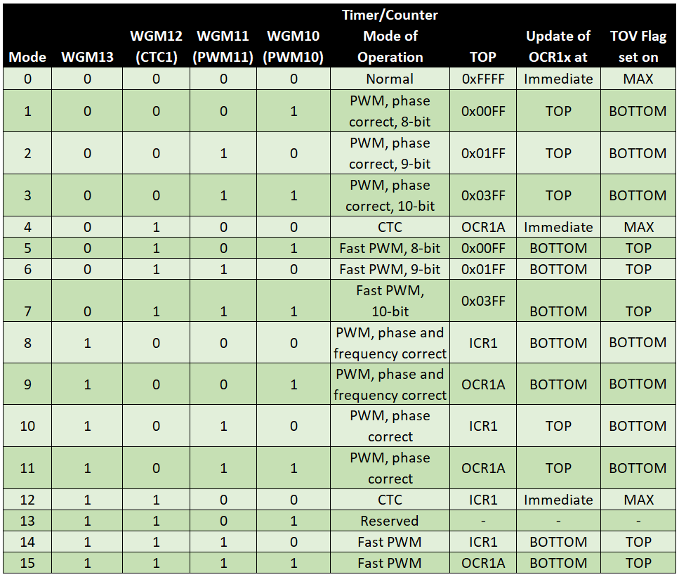
The Wave Form Generator Mode Bits WGM1x define the (PWM) mode. There are 12 PWM modes and 3 non-PWM modes available. We consider only the latter:
- Normal Mode 0: the timer counter counts up to 216 – 1 = 65535.
- To select this mode, no WGM1x bit is to be set.
- Clear Timer on Compare (CTC) Mode 4: the timer counter counts up to OCR1A (Output Compare Register A).
- To select this mode, set WGM12.
- Clear Timer on Compare Mode 12: the timer counter counts up to ICR1 (Input Capture Register 1). To select this mode, set WGM12 and WGM13.
For the full list of modes, click here: WGM1 table.
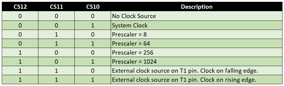
To select the prescaler, set the CS1x bits according to the following scheme:
Finally, activate the timer interrupts you want to use in the Timer1 Interrupt Mask Register TIMSK1.

- TOIE1: Timer Overflow Interrupt Enable – is triggered when the timer overflows.
- OCIE1A: Output Compare A Match Interrupt Enable – triggered when the timer counter matches OCR1A (Output Compare Register A).
- OCIE1B: Output Compare B Match Interrupt Enable – triggered when the timer counter matches OCR1B (Output Compare Register B).
- ICIE1: By setting the Input Capture Interrupt Enable bit, you achieve that an interrupt is triggered when a signal is detected at ICP1 (PB0 / Pin 8). This opens the possibility to use ICP1 like an additional external interrupt pin (see appendix).
Well, completely confused? Don’t worry, with the examples it should become clearer. But a little bit of theory is still missing.
Calculation of the interrupt frequency
The frequency at which the timer counter register TCNT1 counts up is the system clock divided by the prescaler:
![\[ f_{TCNT1} = \frac{system\_clock}{prescaler} \]](https://wolles-elektronikkiste.de/wp-content/ql-cache/quicklatex.com-9fb801e9743184be22805684308dedd7_l3.png "Rendered by QuickLaTeX.com")
The maximum value to which the timer counts up is called “Top”. In Normal mode, Top is 65535. Since the timer counter starts at 0, this is 65536 steps. This results in the overflow frequency:
![\[ f_{timer1\_overflow} = \frac{system\_clock}{65536\cdot prescaler} \]](https://wolles-elektronikkiste.de/wp-content/ql-cache/quicklatex.com-b92b22c276c311ad56f38d767fd1390c_l3.png "Rendered by QuickLaTeX.com")
Interrupt frequency in CTC mode (4)
In CTC mode (4), Top is equal to OCR1A. The frequency of compare matches is:
![\[ f_{OCR1A\_match\_CTC4} = \frac{system\_clock}{(1 + OCR1A)\cdot prescaler} \]](https://wolles-elektronikkiste.de/wp-content/ql-cache/quicklatex.com-4123990e061cdccbe712da13b947f471_l3.png "Rendered by QuickLaTeX.com")
To calculate a certain interrupt frequency (fdesired) at a given system clock, solve the equation to OCR1A.
![\[ OCR1A = \frac{system\_clock}{prescaler\cdot f_{desired}}-1 \]](https://wolles-elektronikkiste.de/wp-content/ql-cache/quicklatex.com-d3fa7d8ae6eb6408f4ce941ed8dea1a6_l3.png "Rendered by QuickLaTeX.com")
Unfortunately, we have a second unknown, namely prescaler. You determine the prescaler first. It must be chosen so that OCR1A is equal or less than 65535. Either you just try a little bit or you use the following formula for the calculation:
![\[ prescaler \geq \frac{system\_clock}{65536\cdot f_{desired}} \]](https://wolles-elektronikkiste.de/wp-content/ql-cache/quicklatex.com-5ce27b7f2c306b4bb23e68c1ef3d1093_l3.png "Rendered by QuickLaTeX.com")
Calculate the right side of the equation and then choose the next larger available prescaler.
For CTC mode 12 you only have to replace OCR1A with ICR1.
Interrupt frequency in normal mode (0)
As already mentioned, 65535 is Top for Timer1 in Normal mode. Here you can control the overflow frequency by specifying a start value, counter_start. The calculations for this are:
![\[ f_{desired\_Normal\_Mode} = \frac{system\_clock}{(65536-counter\_start)\cdot prescaler} \]](https://wolles-elektronikkiste.de/wp-content/ql-cache/quicklatex.com-256f4c25665f2e3bdf4fbd7f190f76e0_l3.png "Rendered by QuickLaTeX.com")
![\[ counter\_start = 65536 - \frac{system\_clock}{prescaler\cdot f_{desired}} \]](https://wolles-elektronikkiste.de/wp-content/ql-cache/quicklatex.com-69de4fd2be0be3753b5bd7d734ff54e1_l3.png "Rendered by QuickLaTeX.com")
Practical examples
Timer interrupts in CTC mode
Done – now we come to the practice. To “warm up” we generate an interrupt every two seconds in CTC mode(fdesired = 0.5). We use the interrupt to toggle an LED at pin 7, i.e. to switch it on or off depending on its state. At 16 MHz, the only possible prescaler is 1024. OCR1A is 31249. The interrupt vector is TIMER1_COMPA_vect.
void setup(){
    TCCR1A = 0x00; // OC2A and OC2B disconnected; Wave Form Generator: Normal Mode
    TCCR1B = (1<<WGM12) | (1<<CS12) |(1<<CS10); // CTC-Mode 4, prescaler = 1024;
    TIMSK1 = (1<<OCIE1A); // interrupt on OCR1A match
    OCR1A = 31249;
    DDRD |= (1<<PD7);  // pinMode(7, OUTPUT);
}

void loop() {}

ISR(TIMER1_COMPA_vect){
    PORTD ^= (1<<PD7);  // toggle Pin 7
}
Timer interrupts in normal mode
And now the same again in Normal Mode. For the start value we calculate 34286. The start value must be set again in the ISR after each interrupt. This time TIMER_OVF_vect is to be selected as interrupt vector.
unsigned int counterStart = 34286;

void setup(){
  TCCR1A = 0x00; // OC2A and OC2B disconnected; Wave Form Generator: Normal Mode
  TCCR1B = (1<<CS12) |(1<<CS10); // prescaler = 1024;
  TIMSK1 = (1<<TOIE1); // interrupt when TCNT1 is overflowed
  TCNT1 = counterStart;
  DDRD |= (1<<PD7);
}

void loop() {
 // do something else
}

ISR(TIMER1_OVF_vect){
  TCNT1 = counterStart;
  PORTD ^= (1<<PD7);
}
Using multiple Timer1 interrupts
In the next example we use the Compare Match A, the Compare Match B and the Overflow Interrupt. With this, we will toggle one LED at 2-second intervals, another at 1-second intervals, and finally a third at 2⁄3-second intervals.
We take the last sketch as a basis and have thus covered the 2-second cycle. We toggle the second LED halfway between the start value (34286) and Top+1 (65536). As interrupt, we use the Compare Match B, i.e. OCR1B is 49911. Additionally we toggle the second LED at TOP.
For LED No. 3, we divide the distance Start → Top+1 into three parts. Again, we toggle at Top, so we still need two interrupts, but we only have Compare Match A left. We solve this problem by reassigning the value of OCR1A after each Compare Match A interrupt.
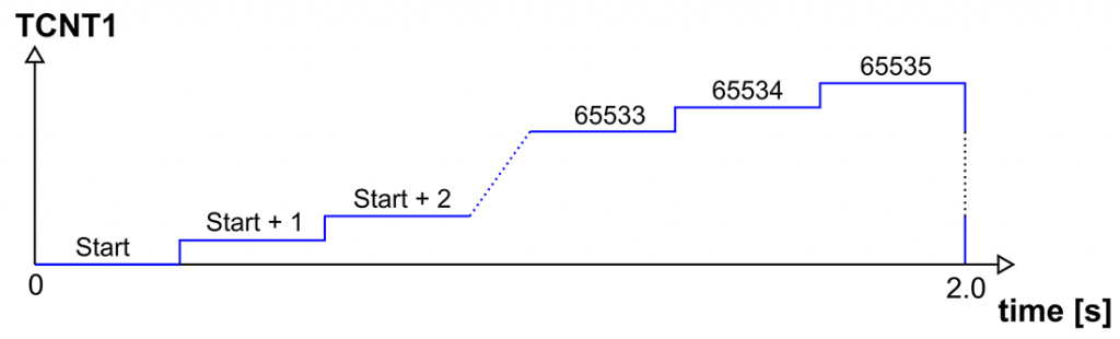
This is how it looks schematically:

The scheme is misleading in that it gives the impression that two seconds have passed when TOP (65535) is reached. However, this is not correct because the two seconds are only over when the counter switches from 65535 to 0. And this is also the reason why you have to subtract the start value from 65536 and not from 65535 to get the number of steps. This becomes clearer if the steps are represented as stair steps. If the start value were 65533, it would be three steps to the overflow:
With 5, 6 and 7 (or PD5, PD6 and PD7) as LED pins the sketch looks like this:
unsigned int counterStart = 34286;

void setup(){
    TCCR1A = 0x00; // OC2A and OC2B disconnected; Wave Form Generator: Normal Mode
    TCCR1B = (1<<CS12)|(1<<CS10); // prescaler = 1024;
    OCR1A = 44703;
    OCR1B = 49911;
    TIMSK1 = (1<<OCIE1B) | (1<<OCIE1A) | (1<<TOIE1);  // interrupt when TCNT1 is overflowed and on commpare matches
    TCNT1 = counterStart;
    DDRD |= (1<<PD7) | (1<<PD6) | (1<<PD5);
}

void loop() {}

ISR(TIMER1_COMPA_vect){
    PORTD ^= (1<<PD5);
    if(OCR1A==44703){
        OCR1A = 55119;
    }
    else
        OCR1A = 44703;
}

ISR(TIMER1_COMPB_vect){
    PORTD ^= (1<<PD6);
}

ISR(TIMER1_OVF_vect){
    TCNT1 = counterStart;
    PORTD ^= (1<<PD7) | (1<<PD6) | (1<<PD5);
}
If you just want to toggle pins, then there is a much easier way, and that is via OC1A and OC1B (Timer1 Output Compare Match A/B Output). These outputs can be toggled automatically in case of a compare match, without having to call an ISR each time. This leads halfway to PWM.
Using Arduino Web Timers
You don’t feel like looking for the correct registers and bits in the data sheet tables over and over again? In this case, I recommend the tool Arduino Web Timers. You just click on what you want to achieve and set the desired frequency via a slider. The code is created automatically.

Arduino Web Timers does not only work with the ATmega328P, but also with the LGT8F328P.
AVR Timer Library TimerOne
If you want to be very comfortable, you could use the TimerOne library. It is compatible with AVR MCUs or boards based on them, and with the LGT8F328P. The library can be installed via the library manager of the Arduino IDE.
Here is a simple example that should be self-explanatory:
#include <TimerOne.h>
const int ledPin = 5;

void setup(void) {
    pinMode(ledPin, OUTPUT);
    Timer1.initialize(500000);  // Time in µs
    Timer1.attachInterrupt(blinkLED);
    Serial.begin(9600);
}

void blinkLED(void) {
    digitalWrite(ledPin,!digitalRead(ledPin));
}

void loop() {
//    delay(2000);  // will not delay the blinking
}
Timer interrupts on the ATtiny85 / ATtiny45 / ATtiny25
As an example of another AVR microcontroller, I have chosen the ATtiny85, which is identical in this respect to the ATtiny45 and the ATtiny25. These MCUs have two 8-bit timers, namely Timer0 and Timer1.
Again, a pin is to toggle every 2 seconds using Timer1. The ATtinys of this series offer a large maximum prescaler of 16384, but the minimum timer overflow frequency is limited by the 8 bits at 8 MHz to ~1.9 Hz. We help ourselves with a counter that we increment with each overflow.
I don’t want to make this post too long. Therefore, I won’t go through all the details like I did with the ATmega328P. Take a look at the data sheet of the ATtinyx5 series. There you will find all the registers and bits for Timer1 in chapter 12.3.
Normal mode
This is how the sketch looks for Normal Mode:
volatile int isrCounter = 0;
const byte counterStart = 12;  // at 8 MHz, overflow frequency is: ~2.0012 Hz

void setup(){
    TCCR1 = (1<<CS13) | (1<<CS12) | (1<<CS11) | (1<<CS10); // Normal Mode, prescaler 16384
    TIMSK = (1<<TOV1); // interrupt on TCNT1 overflow
    DDRB |= (1<<PB4);  // pinMode(4, OUTPUT);
}

void loop() {}

ISR(TIMER1_OVF_vect){
    isrCounter++;
    TCNT1 = counterStart;
    if(isrCounter == 4){ // to achieve 0.5 Hz
        PORTB ^= (1<<PB4);  // toggle Pin 4
        isrCounter = 0;
    }
}
Since the desired frquency of 0.5 Hertz is not directly achievable, I first calculated how many steps the timer counter should theoretically count at 8 MHz and a prescaler of 16384. That is 8000000 / (16384 * 0.5) = approx. 976. However, the maximum number of steps is 256. 2 Hertz, on the other hand, would work (~244 steps). Thus the timer counter start value is 12 and the overflow frequency is approx. 2.0012 Hertz.
CTC Mode
For the sake of completeness, here is the corresponding sketch in CTC mode. This works different to the ATmega328P. The interrupt is triggered on an OCR1A Compare Match. In case of a Compare Match with OCR1C, the counter is reset. By assigning the same value to OCR1A and OCR1C, we basically create a PWM signal with a duty cycle of 100%.
volatile int isrCounter = 0;

void setup(){
/* CTC-Mode -> TCNT1 set to 0 at compare match with OCR1C;
 * PWM1A -> enables PWM mode based on comparator OCR1A in Timer/Counter1 and
 *          the counter value is reset to 0 in the CPU clock cycle after a
 *          compare match with OCR1C register value
 * prescaler = 16384;
 */
    TCCR1 = (1<<CTC1) | (1<<PWM1A) | (1<<CS13) | (1<<CS12) | (1<<CS11) | (1<<CS10);
    TIMSK = (1<<OCIE1A); // interrupt on OCR1A match
    OCR1A = 243; // at 8 MHz, compare match frequency is: ~2.0012 Hz
    OCR1C = 243;
    DDRB |= (1<<PB4);  // pinMode(4, OUTPUT);
}

void loop() {}

ISR(TIMER1_COMPA_vect){
    isrCounter++;
    if(isrCounter == 4){ // to achieve 0.5 Hz
        PORTB ^= (1<<PB4);  // toggle Pin 4
        isrCounter = 0;
    }
}
Timer interrupts on the ESP32
Now we come to the timer interrupts using the ESP32. The good news first: Compared to the AVR based Arduinos the setup is much easier.
The ESP32 has four 64-bit timers (exception: the ESP32-C3 has two) and for each of them you can set up an interrupt. The timer counts according to the system frequency (i.e. normally 80 MHz) and can be slowed down by a prescaler.
Setting up a single timer interrupt
Here is a simple example sketch:
const int ledPin = 16;
hw_timer_t * myTimer = NULL;

void IRAM_ATTR onTimer(){  // timer interrupt ISR
    digitalWrite(ledPin, !digitalRead(ledPin));
}

void setup() {
    pinMode(ledPin, OUTPUT);
    uint64_t alarmLimit = 1500000;
    myTimer = timerBegin(1000000); // timer frequency
    timerAttachInterrupt(myTimer, &onTimer);
    timerAlarm(myTimer, alarmLimit, true, 0);
}

void loop() {}
By the way, I tested the sketch with different ESP32 development boards, namely an ESP32-WROOM-32, an ESP32C3, an ESP32S3 and the ESP32S Dev Kit C.
The ESP32 board package from version 3.0.0 is not backwards compatible with previous versions in terms of timers. This and the following sketch are adapted to the newer version.
Explanation of esp32_1_timer.ino
hw_timer_t * myTimer = NULL;creates the variabletimerof type hw_timer_t (hardware timer) as pointer.- With
timer = timerBegin(1000000);,timer“is filled with life”. The parameter is the counting frequency of the timer. According to my According to my tests, the frequency must not be higher than 40 MHz and not lower than 1250 Hertz. timerAttachInterrupt: Assigns an ISR to the timer.timerAlarm: Defines the interrupt condition, i.e. the counter at which the interrupt is triggered. You pass four parameters to this function:- The timer.
- The alarm limit. The interrupt frequency is: alarmLimit / timer frequency.
truemeans that the timer alarm will be restarted automatically (autoreload).- The fourth parameter is the number of repetitions of the timer alarm (0 = infinite). The value only has an effect if autoreload is false.
Setting up four timer interrupts
In principle, it is simple to set up four timer interrupts. You only have to define a separate variable, a separate ISR and the individual interrupt conditions for each timer. To avoid a lot of typing, we can use arrays. This is actually simple too, but since not everyone might know how to create an array of functions, here’s another sketch for that:
const int ledPin[] = {16, 17, 18, 19};
hw_timer_t* myTimer[4] = {NULL};

void IRAM_ATTR onTimer0(){
    digitalWrite(ledPin[0], !digitalRead(ledPin[0]));
}

void IRAM_ATTR onTimer1(){
    digitalWrite(ledPin[1], !digitalRead(ledPin[1]));
}

void IRAM_ATTR onTimer2(){
    digitalWrite(ledPin[2], !digitalRead(ledPin[2]));
}

void IRAM_ATTR onTimer3(){
    digitalWrite(ledPin[3], !digitalRead(ledPin[3]));
}

void (*onTimer[4])(void) = {onTimer0, onTimer1, onTimer2, onTimer3};  // array of functions

void setup() {
    unsigned int alarmLimit[] = {500000, 750000, 1250000, 1500000}; // int size is 4 bytes n the ESP32!
    for(int i=0; i<4; i++){
        pinMode(ledPin[i], OUTPUT);
        myTimer[i] = timerBegin(1000000);
        timerAttachInterrupt(myTimer[i], onTimer[i]);
        timerAlarm(myTimer[i], alarmLimit[i], true, 0);
    }
}

void loop() {}
More useful functions for the timers of the ESP32 can be found here in the Arduino ESP32 API – documentation.
Timer interrupts on the ESP8266
The ESP8266 has two timers, namely Timer0 and Timer1, whereby Timer0 is required for WiFi and is therefore not freely available. Setting up a timer interrupt on the ESP8266 is again a little less convenient unless you use a library.
Timer interrupts without library
Here is an example for a timer interrupt without using a library (tested on the Wemos D1 mini board).
const int ledPin = D2;

void IRAM_ATTR timer1ISR() {
    digitalWrite(ledPin, !digitalRead(ledPin));
}

void setup(){
    pinMode(D2, OUTPUT);
    timer1_attachInterrupt(timer1ISR);

    /* Prescalers:
        TIM_DIV1      80MHz => 80 ticks/µs => Max: (2^23 / 80) µs =  ~0.105s
        TIM_DIV16     5MHz  => 5 ticks/µs => Max: (2^23 / 5) µs = ~1.678s
        TIM_DIV256    0.3125MHz => 0.3125 ticks/µs => Max: (2^23 / 0,3125) µs = ~26.8s
      Interrupt TYPE:
        TIM_EDGE      no other choice here
      Repeat?:
        TIM_SINGLE  0 => one time interrupt, you need another timer1_write(ticks); to restart
        TIM_LOOP    1 => regular interrupt
    */
    timer1_enable(TIM_DIV16, TIM_EDGE, TIM_LOOP);
    timer1_write(2500000); // 2500000 / 5 ticks/µs => 0.5s interval
}

void loop(){}
Explanation of esp8266_timer.ino
Timer1 counter has a size of 23 bits. That sounds like a lot, but at 80 MHz it overflows about every 0.105 seconds. With the prescaler (TIM_DIV) 16 and 256, this time span can be extended to ~1.678 and ~26.8 seconds.
timer1_attachInterrupt()defines the ISR for the interrupt.timer1_detachInterrupt()deactivates the interrupt.
- With
timer1_enable()you define the prescaler and whether the timer should be activated once or permanently.timer1_disable()deactivates Timer1.
timer1_write()starts the countdown at the defined counter value. So the counter counts down and triggers the interrupt at 0.timer1_read()reads the Timer1 counter.
The value to be passed to timer1_write(), “Timerpreload“, results from the system clock, the prescaler “presc” and the desired frequency “fdesired” or the desired period “perioddesired” :
![\[ \text{Timer}_{\text{preload}} = \frac{80000000}{ \text{presc} \cdot \text{f}_{\text{desired}} } = \frac{80000000}{ \text{presc} } \cdot \text{period}_{\text{desired}} \]](https://wolles-elektronikkiste.de/wp-content/ql-cache/quicklatex.com-c3f6091cde490e2c4d1076f7cc4c6659_l3.png "Rendered by QuickLaTeX.com")
Timer interrupts using the Ticker library
If you want it to be easier, you should use the Ticker library. You don’t have to install it because it is part of the Arduino ESP8266 package. I think the example is self-explanatory:
#include <Ticker.h>
Ticker blinker;

const int ledPin = 2;

void blinkLED(){
    digitalWrite(ledPin, !(digitalRead(ledPin)));
}

void setup(){
    pinMode(ledPin, OUTPUT);
    //Initialize Ticker every 0.5s
    blinker.attach(0.5, blinkLED); // use attach_ms for milliseconds
}

void loop() {}
Cross-MCU timer libraries
But aren’t there cross-MCU libraries for timer interrupts? Unfortunately no, at least none that I know of. What does exist, however, are cross-MCU timer libraries that work based on millis(), such as arduino-timer or TickTwo. You can install it via the library manager of the Arduino IDE.
The disadvantage of these solutions is that you have to actively query whether the defined time period has expired. If you uncomment the delays in the main loops of the following example sketches, you will notice that the blink frequency decreases accordingly.
arduino-timer
Here is the example sketch for arduino-timer:
#include <arduino-timer.h>
const int ledPin = 5;

auto timer = timer_create_default();

bool blinkLED(void *) {
    digitalWrite(ledPin, !digitalRead(ledPin)); // toggle the LED
    return true; // in case you want to stop the timer choose false
}

void setup() {
    pinMode(ledPin, OUTPUT); // set LED pin to OUTPUT
    timer.every(500, blinkLED);
}

void loop() {
    timer.tick();
//    delay(2000);  // will delay the blinking
}
TickTwo
And here is the sample sketch for TickTwo:
#include "TickTwo.h"
const int ledPin = 5;

void blinkLED() {
  digitalWrite(ledPin, !digitalRead(ledPin));
}

TickTwo timer(blinkLED, 500);

void setup() {
    pinMode(ledPin, OUTPUT);
    timer.start();
}

void loop() {
    timer.update();
//    delay(2000); // will delay the blinking
}
Appendix – Using ICP1 like an external interrupt pin
Finally, I come back to the timer1 of the ATmega328P. Namely, I want to show how you can use the Input Capture Interrupt so that ICP1 (PB0/Pin 8) behaves like an external interrupt pin.
const int ledPin = 13;
const int icp1Pin = 8;
volatile bool event = false;

ISR(TIMER1_CAPT_vect){
   event = true;
}

void setup() {
    pinMode(icp1Pin, INPUT);
    pinMode(ledPin, OUTPUT);
//    TCCR1B = (1<<ICES1);  // rising edge
    TCCR1B =  (1<<ICNC1) |  (1<<ICES1);  // with noise cancelling
    TIMSK1 = (1<<ICIE1);
}

void loop() {
    if(event){
        digitalWrite(ledPin, HIGH);
        delay(500);
        digitalWrite(ledPin, LOW);
        event = false;
    }
}
The following bits are relevant here:
- ICES1: If the bit is set, the interrupt is triggered on a rising edge.
- ICNC1: If you set this bit, the interrupt is only triggered if ICP1 fulfills the interrupt condition over the period of four clocks (NC = noise-cancelling).
- ICIE1: activates the Input Capture Interrupt.
Acknowledgement
I created my post image from different components. I owe the time-out gesture to Gerd Altmann, the hourglass to Felipe and the background image (Arduino UNO) to federicoag, all found on Pixabay.
Вдруг пригодится
у ESP8266 Wemos при изменении частоты с 80 МГц на 160 Мгц – счётчик на основе ESP.getCycleCount() начинает идти в 2 раза медленнее!!!
Ну мало ли – я слишком потратил много времени чтобы понять это нигде незадокументированную фичу )))
Translation added by Wolfgang:
It might come in handy
When changing the frequency from 80 MHz to 160 MHz on the ESP8266 Wemos, the counter based on ESP.getCycleCount() starts running twice as slow!!!
Well, you never know – I spent too much time figuring out this undocumented feature )))
Thanks for the comment. Of course, if you change the default system clock, then you will need to recalculate. It should be clear when reading the explanations to the sketch.
Hi Wolfgang,
do you know the difference between “TIM_EDGE” and “TIM_LEVEL”
Hi Frank I have only a rough understanding. TIM_EDGE and TIM_LEVEL are interrupt types. TIM_EDGE is triggered once when the interrupt condition is met, e.g. when the counter matches a certain value. It is edge-initiated. My understanding is that is corresponds to the RISING or FALLING or CHANGE parameters you know from attachInterrupt(). TIM_LEVEL is constantly triggered as long as the interrupt condition is met, e.g. while the counter exceeds a certain value. This would correspond to the HIGH or LOW parameters for attachInterrupt(). I have read somewhere that you can’t use TIM_LEVEL interrupts on Timer1. But I don’t know more details – thin ice for me.
Hi Frank, thanks for the hint. Regards, Wolfgang
Ah I saw the explanation is also in the german site.
I looked into the english one 🙂
Hi Frank, no, I have just updated the German and the English version because of your comment! Thanks again!
Hello Wolle,
just read the timer example for the ESP8266.
It is not so complicated to calculate the timer values.
Lets assume:
T = 1/f * Prescaler
Timer Preload = f / Prescaler * t_trigger
Timer Preload = 80 MHz / 16 * 0,5 s = 2500000
So could be placed in a pretty function.