About this Post
Interrupts can be used to elegantly overcome many challenges in programming Arduino boards or other microcontrollers. However, there are a number of stumbling blocks when using them. In addition, the programming of interrupts is quite hardware-specific.
There are actually already more than enough articles about external interrupts on the net, and many of them are excellent. My motivation for writing my own contribution was to go a little deeper into some aspects. Maybe one or the other advanced reader will also find some new details. However, this has made this post quite lengthy, even in two parts.
After a general introduction, the first part deals with external interrupts. These are the topics I will discuss:
- What is an interrupt?
- Which interrupts are available?
- External interrupts
- Hardware vs. software interrupts
- ATmega328P – Programming external interrupts on register level
- Interrupts on other MCUs / boards
What is an interrupt?
When programming, we are used to thinking sequentially, i.e., that instructions are executed one after the other. Now imagine, for example, that pressing a button is supposed to switch an LED on or off. You could check whether the button has been pressed using digitalRead(). There are two options for this:
- You permanently query the button state, for example in a while loop. So you stop the program at this point until the button is pressed.
- If a loop() pass is shorter than a button press takes, then you could insert the
digitalRead()query without a blocking element.
Both may be acceptable in some circumstances. But what if the program has to keep running because other tasks need to be done regularly? And what if processing these tasks takes longer than pressing the button? That’s where the interrupts are helpful.
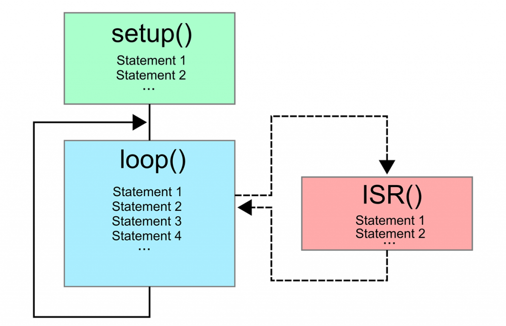
For an interrupt, you need two things, namely a trigger and an action (Interrupt Service Routine = ISR). When the trigger condition is met, the program jumps to the ISR, executes the instructions specified there, and jumps back to where it was interrupted:
Which interrupts are available?
Microcontrollers use many different interrupts. In part, you use them without realizing it because the underlying code is implemented in libraries and macros. An example of this is the Timer0 overflow, which is used on AVR-based Arduino boards for the function millis().
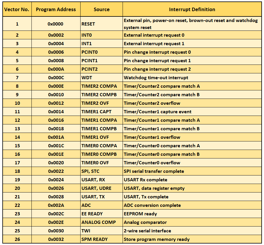
Which interrupts are available is hardware-specific. Here is an overview of the interrupts of the ATmega328P (Arduino UNO, Nano, Pro Mini):
Virtually every microcontroller has interrupts that are triggered by an external event, such as a pin level change (HIGH/LOW, LOW/HIGH). For the ATmega328P, these are the interrupts INT0 and INT1. In the Arduino world, you control this kind of interrupt via attachInterrupt(). The nice thing about this is that if you change the microcontroller, e.g. from an Arduino UNO to an ESP32, you only have to modify the code slightly.
Other useful interrupts, like timer interrupts, watchdog timer interrupts or pin change interrupts are implemented so specifically on the microcontrollers that they have not been made accessible (directly) via Arduino functions. Nevertheless, there are Arduino functions that use these interrupts in the background, like the already mentioned millis().
External interrupts
We turn to the external interrupts using the ATmega328P based Arduino boards (Arduino UNO, Nano, Pro Mini) as an example. A button press is to trigger an interrupt. In response, the board LED of the Arduino should light up for half a second. For this purpose, the following circuit could be used. It pulls the interrupt pin D2 to LOW and triggers a HIGH signal when the push button is pressed:

Note that the connectors on the left side of the push button are permanently connected. And here is the corresponding sketch:
const int ledPin = 13; // On-board LED
const int interruptPin = 2;
volatile bool event = false;

void eventISR(){
    event = true;
}

void setup() {
    pinMode(interruptPin, INPUT);
    pinMode(ledPin, OUTPUT);
    attachInterrupt(digitalPinToInterrupt(interruptPin), eventISR, RISING);
}

void loop() {
    if(event){
        digitalWrite(ledPin, HIGH);
        delay(500);
        digitalWrite(ledPin, LOW);
        event = false;
    }
}
Explanations about interrupt_basic.ino
The function attachInterrupt(interrupt, ISR, mode) configures the interrupt. The three parameters are:
- interrupt: number of the interrupt (provided by
digitalPinToInterrupt(interruptPin)) - ISR: Interrupt Service Routine
- mode: mode (LOW, RISING, FALLING, CHANGE)
The ATmega328P has two external interrupts, namely INT0 (on Arduino pin 2) and INT1 (on Arduino pin 3). So that you do not have to search out the interrupt numbers, but can simply select the appropriate pins, use digitalPinToInterrupt(pin). With pin = 2 the function returns 0.
The ISR is called when the interrupt has been triggered.
The mode specifies more precisely under which conditions the interrupt is triggered:
- LOW: Pin level is LOW.
- RISING: Change from LOW to HIGH (rising edge).
- FALLING: Change from HIGH to LOW (falling edge).
- CHANGE: Change HIGH / LOW or LOW / HIGH.
By the way, it would have been easier to reverse the logic of the above circuit, i.e. to provide for a HIGH-LOW transition (“FALLING”) when the button is pressed. By using the internal pull-up resistor, we could have saved the external resistor.
The specifics of the ISR as a function
For the ISR, note:
- You do not pass any parameters to the ISR and do not let it return anything.
- The ISR should always be kept as short as possible.
- For some boards, the ISR must be placed before
setup(). That’s why I’m doing it this way throughout this post. - Global variables that you change in the ISR must be defined with the keyword
volatile. - Within the ISR, all further interrupts are suspended.
The last point needs a few more explanations. If the conditions for another interrupt occur during the execution of the ISR, the interrupt flags of the responsible registers are set, but otherwise the interrupt remains without consequences for the moment. No other ISRs can be called from an ISR.
Since delay() is interrupt-based, it does not work in the ISR. millis() itself works, but the time within the ISR stops because timekeeping is based on Timer0 interrupts.
As that might sound a bit theoretical, I would like to illustrate it with a sample sketch. But this means I have to break the rule about keeping ISRs short. So: don’t write ISRs like this! Don’t use delay() or Serial.print() in ISRs. This example is meant to show why you shouldn’t do it this way.
const int ledPin = 13;
const int interruptPin = 2;
volatile bool event = false;

void eventISR(){
    unsigned long x = 0;

    x = millis();
    Serial.println(x);  // bad style!
    Serial.flush();

    myDelay(2000);  // bad style!

    x = millis();
    Serial.println(x);  // bad style
    Serial.flush();  // bad style

    event = true;
}

void setup() {
    Serial.begin(9600);
    pinMode(interruptPin, INPUT);
    pinMode(ledPin, OUTPUT);
    attachInterrupt(digitalPinToInterrupt(interruptPin), eventISR, RISING);
}

void loop() {
    if(event){
        digitalWrite(ledPin, HIGH);
        delay(500);
        digitalWrite(ledPin, LOW);
        event = false;
    }
}

void myDelay(unsigned int milli_secs) {
    for(unsigned int i=0; i<milli_secs; i++){
        delayMicroseconds(1000);
    }
}
And this is the output:

Conclusions from the sketch
From the above output, we can draw the following conclusions:
delayMicroseconds()works in the ISR (even if it is not a good style!).- The time between the calls of
millis()has stopped. A good reason to keep ISRs short. - The microcontroller is not “deaf” to new interrupts while the ISR is executing.
On the last point: Actually, you would expect pairs of two identical values, but sometimes there are four of them. The reason for this is the button bounce, which causes the interrupt condition to be met again while the ISR is still busy processing the current interrupt. More precisely expressed: With the jump into the ISR, the interrupt flag in the responsible register is cleared. A re-occurring interrupt condition resets it, but this is of no consequence during the execution of the ISR. This changes after exiting the ISR, hence the program immediately jumps back to the ISR. A “six-pack” of identical values does not occur because the bouncing is shorter than the processing of the ISR and the interrupt flag can only be set once.
What does “volatile” do in detail?
It is not entirely straightforward to explain why volatile must be used when modifying variables in an ISR.
Variables are stored in the SRAM. To be able to use them during the program run in the ALU (Arithmetic Logic Unit) for arithmetic or comparison operations, they must be read from SRAM. However, access to the SRAM is relatively slow. Therefore, there are registers for faster access, where copies of the variables can be stored temporarily. The ATmega328P is equipped with 32 8-bit registers for this purpose.
The compiler attempts to use this resource efficiently. To this end, it ensures that variables do not have to be re-read from SRAM every time they are accessed, provided that copies are already stored in registers. The compiler “knows” at all times where the current value is located – at least from its perspective within the current program flow.
This becomes problematic when a variable is modified outside this normal programme flow, for example, in an ISR. The compiler cannot detect that the variable’s value may change asynchronously and therefore assumes that its value remains unchanged between two accesses.
In this case, the compiler may only work with a cached copy, meaning that changes made by the ISR are ignored.
volatile solves this problem by instructing the compiler to read the value directly from the SRAM each time it is accessed, rather than using cached copies.
This may cause the process to run slightly slower, though in practice this is usually of no consequence.
Dealing with large volatile variables in ISRs
It gets even worse, so to speak: the ATmega328P is an 8-bit microcontroller. Consequently, an Arduino based on this chip – such as the UNO, Nano or Pro Mini – requires several clock cycles to read or write a variable larger than one byte.
If, for example, you use a volatile variable of type long (4 bytes), this variable is accessed byte by byte from the SRAM.
The following can happen: During this multi-part access, an interrupt is triggered – for example, after two of the four bytes have already been read. Execution then jumps to the interrupt service routine (ISR), where the variable is modified. The programme then returns and continues the access.
The result is an inconsistent value: some of the bytes still come from the old value, whilst the rest come from the new one. This is also referred to as a “torn” access.
volatile does not, therefore, protect against such problems, but merely ensures that access actually takes place.
To avoid such situations, you can temporarily disable interrupts whilst accessing the data:
volatile long anyVariable; // example
...
noInterrupts(); // equals cli();
  // Gebrauch von / use of anyVariable
interrupts(); // equals sei();
Alternatively, you can use the macro ATOMIC_BLOCK for AVR-based Arduino boards:
#include <util/atomic.h>
volatile long anyVariable; // example
...
ATOMIC_BLOCK(ATOMIC_RESTORESTATE) {
  // Gebrauch von / use of anyVariable
}
ATOMIC_BLOCK also ensures that the instructions in the curly brackets are processed undisturbed by interrupts. Furthermore, the macro makes a copy of the status register before suspending the interrupts and writes it back later. I’ll come back to that below.
Debouncing
Blocking debouncing
In the first example sketch interrupt_basic.ino we could ignore the problem of button bouncing. It was simply not noticeable there because calling the very short ISR multiple times had no significant effect on the LED light phase (during delay(500)). Thus, inserting a delay() is an easy way to conceal button bounce, though not necessarily the smartest, since it blocks the sketch.
The oscilloscope shows that the bouncing is still there:
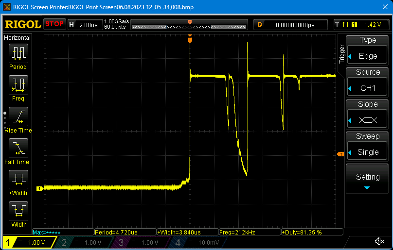

And since the bounce can occur both when the button is pressed and when it is released, the delay must be longer than the button press.
How often the button bounces can be checked with the following sketch because it counts each ISR call:
const int interruptPin = 2;
volatile bool event = false;
volatile unsigned int counter = 0;

void eventISR() {
//    detachInterrupt(digitalPinToInterrupt(interruptPin));
    event = true;
    counter++;
}

void setup() {
    Serial.begin(9600);
    pinMode(interruptPin, INPUT);
    attachInterrupt(digitalPinToInterrupt(interruptPin), eventISR, RISING);
}

void loop() {
    if(event) {
        Serial.print("Number of interrupts: ");
        Serial.println(counter);
        delay(200);
        event = false;
//        EIFR |= (1<<INTF0); // writing a "1" to interrupt flag 0 clears it
//        attachInterrupt(digitalPinToInterrupt(interruptPin), eventISR, RISING);
    }
}
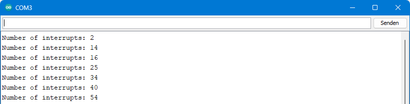
As a result, you get exactly one output per button press on the serial monitor, but several interrupts are recorded. How often the button bounces per press depends on its design and quality. Here is an example:
Debouncing with detachInterrupt()
If you uncomment the lines 6 and 24, the interrupts at pin 2 are switched off with detachInterrupt() and switched on with attachInterrupt(). This is not to be confused with the effect of the functions noInterrupts() and interrupts(), which merely pause or activate the execution of the ISR.
On the serial monitor, you should then see that the “Number of interrupts” only increases by 1 per output – theoretically. Unfortunately, on AVR based Arduinos you might still get two outputs per button press now. Other boards, e.g. based on a LGT8F328P or ESP32, do not show this behavior. Remedy is the active clearing of the interrupt flag before the interrupt is switched on again (line 23).
Non-blocking debouncing
However, even in its improved version, the button_press_counter_I.ino sketch still has two drawbacks:
- Due to the
delay(200)it is blocking. - If you press the button for longer than 200 milliseconds, the bounce on release can cause another interrupt.
We can avoid delays by measuring time via millis() queries. We eliminate the bouncing effect when the button is released by introducing the following condition: A RISING is only valid if the preceding LOW phase is longer than the bouncing.
So, since we also want to measure the duration of the LOW phase, we must also detect falling edges and therefore switch to the interrupt condition CHANGE. We call the maximum bounce time in the following sketch debounceTime. A valid HIGH or LOW state (lastValidState) is only present if it lasts longer than debounceTime.
const int interruptPin = 2;
volatile bool event = false;
volatile unsigned int counter = 0;
volatile int lastValidState = LOW;
volatile unsigned long lastInterrupt = 0;
const unsigned long debounceTime = 20;

void eventISR(){
    if((millis() - lastInterrupt) > debounceTime){
        if( (digitalRead(interruptPin) == HIGH) && (lastValidState == LOW) ){
            event = true;
            lastValidState = HIGH;
            counter++;
        }
        else {
            lastValidState = LOW;
        }
        lastInterrupt = millis();
    }
}

void setup() {
    Serial.begin(9600);
    pinMode(interruptPin, INPUT);
    attachInterrupt(digitalPinToInterrupt(interruptPin), eventISR, CHANGE);
}

void loop() {
    if(event){           // if event
        Serial.print("Number of Interrupts: ");
        Serial.println(counter);
        event = false;
    }
//    delay(4000);
}
When uncommenting line 34 you will see that the valid button presses are diligently collected in the background. So you can let the microcontroller do other things, if you don’t have to react to the interrupt immediately. However, the ISR has turned out to be a bit long.
Alternative non-blocking debouncing
There is more than one way to skin a cat. Here’s a slightly different approach:
const int interruptPin = 2;
volatile byte buttonState = 0;
unsigned int counter = 0;
unsigned long lastCheck = 0;
const unsigned long checkInterval = 10;
byte stateHistory = 0;

void eventISR(){
    buttonState = digitalRead(interruptPin);
}

void setup() {
    Serial.begin(9600);
    pinMode(interruptPin, INPUT);
    attachInterrupt(digitalPinToInterrupt(interruptPin), eventISR, CHANGE);
}

void loop() {
    if((millis() - lastCheck) > checkInterval){
        stateHistory = (stateHistory << 1) | (buttonState);
        if(stateHistory == 1){
            counter++;
            Serial.println(counter);
        }
        lastCheck = millis();
    }
}
The way it works may not be obvious to everyone at first glance. In buttonState the current polarity of the interrupt pin is stored. At intervals of checkInterval the status history stateHistory is shifted one bit to the left and the current status is appended. Since stateHistory is defined as a byte, the history includes eight values. Only if the past seven checks have resulted in a LOW status and the current status is HIGH, the counter is increased.
The advantage over the previous method is the short ISR and the slightly leaner code. Potentially disadvantageous is that loop() must not contain time-eaters such as delays; otherwise the check intervals will be stretched accordingly.
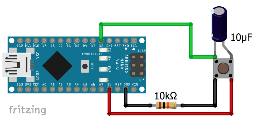
Hardware debouncing using RC circuits
I’m digressing here (even more) from the actual topic of interrupts, but I don’t want to leave hardware debouncing unmentioned. For this purpose, we use an RC circuit, which consists of a resistor and a capacitor.
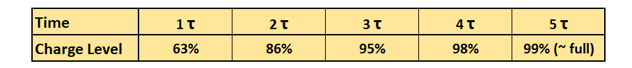
The so-called time constant τ tells us how fast a capacitor is charged across a resistor connected in series:
![\[ \tau\; \text{[s]}= R\; \text{[}\Omega\text{]} \cdot C\; \text{[F]} \]](https://wolles-elektronikkiste.de/wp-content/ql-cache/quicklatex.com-379ddd6ac968421e6e852a90beab3384_l3.png "Rendered by QuickLaTeX.com")
The charging process is not linear:
Here is an example circuit:

A clear high signal is about 0.6 x VCC on an AVR based Arduino. When using an RC circuit, this potential is reached after approx. 1 τ. If you press the button in the circuit above, the capacitor is charged via the 1 kilohm resistor. τ is therefore 1 kilohm x 10 µF = 10 milliseconds.
The 10 kilohm pull-down resistor gets an additional task here. It is part of the RC circuit that becomes active when the button is released. The upper limit for a clear LOW signal is reached at approx. 0.3 x VCC. Since the discharge rate follows the same rules, this is also about 1 τ. Because of the tenfold larger resistance, τ is 100 ms.
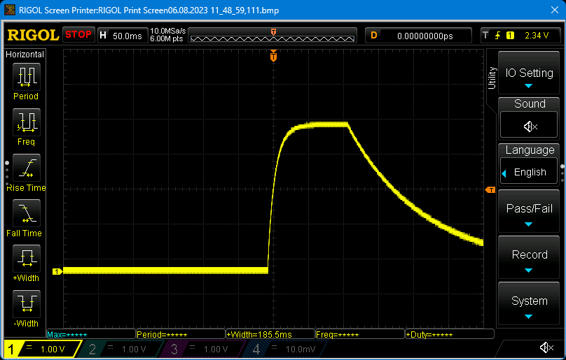
Theory and practice match quite well:
However, I neglected to mention that the two resistors in the above circuit form a voltage divider when the pushbutton is pressed. So I did not choose the resistors of different sizes by chance. With my combination, the maximum voltage at pin D2 is 10/11ths VCC, so in the safe range to reach a HIGH level. It would not work with two resistors of the same size.
In principle, the simpler version shown below should also work (thanks, Neil!). It has the advantage that the switch-on process is much quicker. I had push-buttons where this worked reliably, but with others, this didn’t reliably prevent the bounce effect. Try it best.
Controlled suspension of interrupts with noInterrupts()
I would like to come back to the effect of noInterrupts() and interrupts(). The following sketch shows how these functions work:
const int interruptPin = 2;
const int ledPin = 13;
volatile bool event = false;

void eventISR(){
    event = true;
}

void setup() {
    pinMode(interruptPin, INPUT);
    pinMode(ledPin, OUTPUT);
    attachInterrupt(digitalPinToInterrupt(interruptPin), eventISR, RISING);
}

void loop() {
    noInterrupts();
    for(int i=0; i<4; i++){
        digitalWrite(ledPin, HIGH);
        myDelay(500); // dely would not work
        digitalWrite(ledPin, LOW);
        myDelay(200); // delay would not work
    }
    myDelay(1000);
    interrupts();
    myDelay(1); // little pause between interrupts() and noInterrupts()

    if(event){
        for(int i=0; i<5; i++){
            digitalWrite(ledPin, HIGH);
            delay(50);
            digitalWrite(ledPin, LOW);
            delay(50);
        }
        event = false;
    }
}

void myDelay(unsigned int milli_secs){
  for(unsigned int i=0; i<milli_secs; i++){
    delayMicroseconds(1000);
  }
}
At the beginning of the main loop, the execution of the ISRs is paused by noInterrupts(). Nevertheless, interrupt conditions are detected and the responsible interrupt flags are set. The ISRs are executed after reactivation by interrupts() only at the end of the main loop, which is noticeable in this example by a fast flashing. If you press the button several times during a main loop pass, the ISR is still executed only once because the corresponding interrupt flag (INTF0) can be set only once. If you would set up another external interrupt at D3 (INT1), you could additionally set INTF1. As a result, both ISRs would be processed.
cli() and sei()
Perhaps you have already stumbled across the functions cli() and sei(). These are identical to noInterrupts() and interrupts(). They are just different identifiers assigned via corresponding #define directives in Arduino.h.
And maybe you’ve read that instead of cli() …. sei() you should better use the following code:
uint8_t oldSREG = SREG;
cli();
...
SREG = oldSREG;
The essential difference is that with sei() the interrupts are activated in any case. Saving and writing back the status register SREG, on the other hand, ensures that only the previous state is restored. I.e.: if the interrupts were already deactivated before the execution of cli(), they are not activated with SREG = oldSREG;. In the Arduino world, this is of less importance because interrupts are enabled by default.
External components with interrupt output
Things get a bit complicated if you use external components (sensors or similar) that have their own interrupt output to indicate an event. Example: In case of an interrupt at the component, its interrupt output goes HIGH. On the microcontroller side, you use an interrupt input to detect the event. For most components, their interrupts remain active until certain registers containing measured values or interrupt flags have been read. This reactivates the interrupt function of the component. In the example, the output would go LOW again.
Then a typical error can occur: the component already triggers the next interrupt (interrupt output of the component is HIGH again), while the microcontroller is still processing the actions from the last interrupt. When it is done, it sets the event flag event to false and waits for the next interrupt signal (a RISING). But then the microcontroller can wait forever because the level is already HIGH!
“Arming” the interrupt functions of external components, the setting of the flags and the use of attachInterrupt() / detachInterrupt() must therefore be well timed.
Hardware vs. software interrupts
In many articles, the external interrupts are discussed under the heading “Hardware interrupts”. This is correct, but suggests that all other interrupts, such as the pin change or timer interrupts, belonged to the group of software interrupts. That, in turn, is not true. Most microcontrollers like the 8-bit AVR models used in Arduino boards do not have software interrupts implemented per se. This includes timer overflow interrupts, which are not software interrupts.
However, software interrupts can be implemented using hardware interrupts. For example, on an AVR Arduino, you can set up an interrupt on an external interrupt pin and set the pin to OUTPUT. In doing so, you leave it unconnected. You can then use digitalWrite() to trigger interrupts.
ATmega328P – Programming external interrupts on register level
If you like, you can learn in this chapter how external interrupts work on the ATmega328P on register level. You don’t necessarily need to know this to apply interrupts, but I, personally, find it helpful. In particular, it helps to better understand and avoid bugs.
Status Register SREG
The status register SREG contains a lot of information about arithmetic operations, e.g. whether there is a negative result (bit 2). For interrupts, bit 7 (“I” = Global Interrupt Enable) is of importance. The function noInterrupts() or cli() deletes it, interrupts() or sei() sets it.

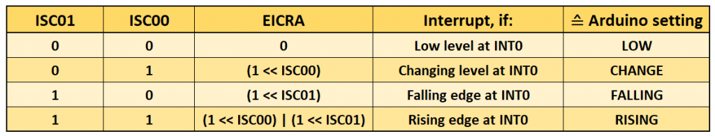
External Interrupt Control Register A – EICRA
In the External Interrupt Control Register A (EICRA) the interrupt conditions (LOW, CHANGE, FALLING or RISING) for the external interrupts INT0 and INT1 are defined.

Bit 0 and bit 1 are responsible for INT0, bit 2 and bit 3 for INT1.
External Interrupt Mask Register
In the External Interrupt Mask Register EIMSK the external interrupts are activated. In the Arduino language, this is done by attachInterrupt(digitalPinToInterrupt(pin), ... , ...).

External Interrupt Flag Register
In the External Interrupt Flag Register EIFR the interrupt flags INTF0 and INTF1 are set when the corresponding interrupt has been triggered. The interrupt flags are cleared when the corresponding ISR is executed. Alternatively, you delete the respective bit by writing a 1 to it.

Example sketch using register instructions
This is what the “translation” of the button_press_counter_I.ino sketch from earlier looks like when we configure the interrupts directly via the registers:
const int interruptPin = 2;
volatile bool event = false;
volatile static unsigned int counter = 0;

ISR (INT0_vect){          // ISR for INT0
    EIMSK &= ~(1<<INT0);  // detach INT0 interrupt
    event = true;
    counter++;
}

void setup() {
    Serial.begin(9600);
    pinMode(interruptPin, INPUT);
    EICRA = (1<<ISC01) | (1<<ISC00);  // Interrupt @ rising edge
    EIMSK = (1<<INT0);
}

void loop() {
    if(event){
        Serial.print("Number of interrupts: ");
        Serial.println(counter);
        delay(200);
        event = false;
        EIFR |= (1<<INTF0); // clear interrupt flag
        EIMSK = (1<<INT0);  // attach INT0 interrupt
    }
}
If you need a third external interrupt
If you need an additional external interrupt, you can use the input capture interrupt on ICP1 (PB0 / Pin 8) for this purpose. I’ll explain how to do this in my upcoming post on timer interrupts.
External interrupts on other MCUs / boards
Arduino Boards
Other Arduino boards, which are not based on the ATmega328P, usually have more than two external interrupt pins. Here is an overview.
The nice thing about the Arduino environment is that you can still use the same functions. The situation is different when you program at register level. In this case, you have to look into the data sheet of the microcontroller.
At this point, a note for the Arduino MEGA 2560: Theoretically you can use pins 2, 3, 18, 19, 20 and 21 as external interrupt pins, but practically pins 20 and 21 cause problems because they are pulled HIGH by default due to their function as I2C pins.
LGT8F328P / MiniEVB Boards
Regarding the external interrupts, the LGT8F328P or the MiniEVB boards based on it are almost identical. Sketches for ATmega328P based boards are transferable 1:1. However, the behavior may differ in detail (as mentioned e.g. in the chapter Debouncing with detachInterrupt).
ATtinys
There is a huge selection of ATtinys that are very conveniently programmable with Spence Konde’s board packages, including interrupts. I have reported on these MCUs here (ATTinyCore) and here (megaTinyCore). Concerning external interrupts, the members of the megaTinyCore family (= tinyAVR 0/1/2) might be interesting for you because external interrupts can be set up on all pins.
ESP32
On the ESP32, you can set up to 32 external interrupts per core – at least theoretically. Practically, this is limited by the number of available pins. In addition, some pins have certain peculiarities that make them unsuitable in general or for certain constellations (see here).
In addition to LOW, CHANGE, FALLING and RISING you can select HIGH as interrupt condition.
Unlike the Arduinos, the ESP32 executes the ISRs program code in its flash memory. To move the ISRs to the faster RAM (more precisely: IRAM = Instruction RAM), you add the attribute IRAM_ATTR. There are other reasons to do this besides the speed advantage, but that would take us too far here.
With the ESP32, it is mandatory to place the ISR before the setup; otherwise, the compilation will abort with an error message.
Here is an example sketch with two LEDs and two pushbuttons:
const int ledPin_1 = 21;
const int ledPin_2 = 18;
const int interruptPin_1 = 16;
const int interruptPin_2 = 12;
volatile bool event_1 = false;
volatile bool event_2 = false;

void IRAM_ATTR eventISR_1(){
    event_1 = true;
}

void IRAM_ATTR eventISR_2(){
    event_2 = true;
}

void setup() {
    pinMode(interruptPin_1, INPUT);
    pinMode(interruptPin_2, INPUT);
    pinMode(ledPin_1, OUTPUT);
    pinMode(ledPin_2, OUTPUT);
    attachInterrupt(digitalPinToInterrupt(interruptPin_1), eventISR_1, RISING);
    attachInterrupt(digitalPinToInterrupt(interruptPin_2), eventISR_2, RISING);
}

void loop() {
    if(event_1){
        digitalWrite(ledPin_1, HIGH);
        delay(2000);
        digitalWrite(ledPin_1, LOW);
        event_1 = false;
    }
    if(event_2){
        digitalWrite(ledPin_2, HIGH);
        delay(2000);
        digitalWrite(ledPin_2, LOW);
        event_2 = false;
    }
}
Subtle differences
The “Arduino language” is very convenient, as it makes porting program code from one microcontroller to another straightforward. On the other hand, subtle differences are sometimes masked in the process. I have modified the sketch ESP32_interrupt_example.ino for this purpose. The instructions for switching the LEDs have been moved to the ISR. This is not a good style and is for illustrative purposes only.
const int ledPin_1 = 21;
const int ledPin_2 = 18;
const int interruptPin_1 = 16;
const int interruptPin_2 = 12;
volatile bool event_1 = false;
volatile bool event_2 = false;

void IRAM_ATTR eventISR_1(){
    digitalWrite(ledPin_1, HIGH);
    myDelay(2000);
    digitalWrite(ledPin_1, LOW);
}

void IRAM_ATTR eventISR_2(){
    digitalWrite(ledPin_2, HIGH);
    myDelay(2000);
    digitalWrite(ledPin_2, LOW);
}

void setup() {
    pinMode(interruptPin_1, INPUT);
    pinMode(interruptPin_2, INPUT);
    pinMode(ledPin_1, OUTPUT);
    pinMode(ledPin_2, OUTPUT);
    attachInterrupt(digitalPinToInterrupt(interruptPin_1), eventISR_1, RISING);
    attachInterrupt(digitalPinToInterrupt(interruptPin_2), eventISR_2, RISING);
}

void loop() {}

void myDelay(unsigned int milli_secs) {
    for(unsigned int i=0; i<milli_secs; i++){
        delayMicroseconds(1000); }
}
If you press the button for LED 2 while LED 1 is lit, there will be no consequences. LED 2 does not light up when LED 1 has stopped. If you now transfer the sketch to an AVR based Arduino (remove IRAM_ATTR and adjust the pins), the behavior changes. Now, LED 2 will light up. In the case of the Arduino, the interrupt flag for button 2 is set and “processed” after ISR 1 is completed.
This shows once again: ISRs should be kept as short as possible. In the case of the ESP32, especially if you set up many external interrupts.
ESP8266
The ESP8266 behaves like the ESP32 regarding interrupts. Also with the ESP8266, there are certain restrictions for some pins. I discussed this here in my post about the Wemos D1 mini boards.
The ISRs necessarily require an attribute. It’s best to take IRAM_ATTR again. It used to be ICACHE_RAM_ATTR. The latter is still working, but triggers a compiler warning.
Conclusion and outlook
External interrupts are very useful to monitor the status of external hardware (in the simplest case, a push button). The big advantage is that you can do without constant queries of the status. On the other hand, interrupts are always a “popular” source of errors. The functionality of interrupts can vary on different boards or microcontrollers. This can lead to surprises when transferring sketches to other boards.
In my next article, I’ll be discussing pin-change interrupts, and in the post after that, I’ll be looking at timers.
Acknowledgement
I created my post image from different components. I owe the time-out gesture to Gerd Altmann, the background image is by federicoag, both found on Pixabay.