About this post
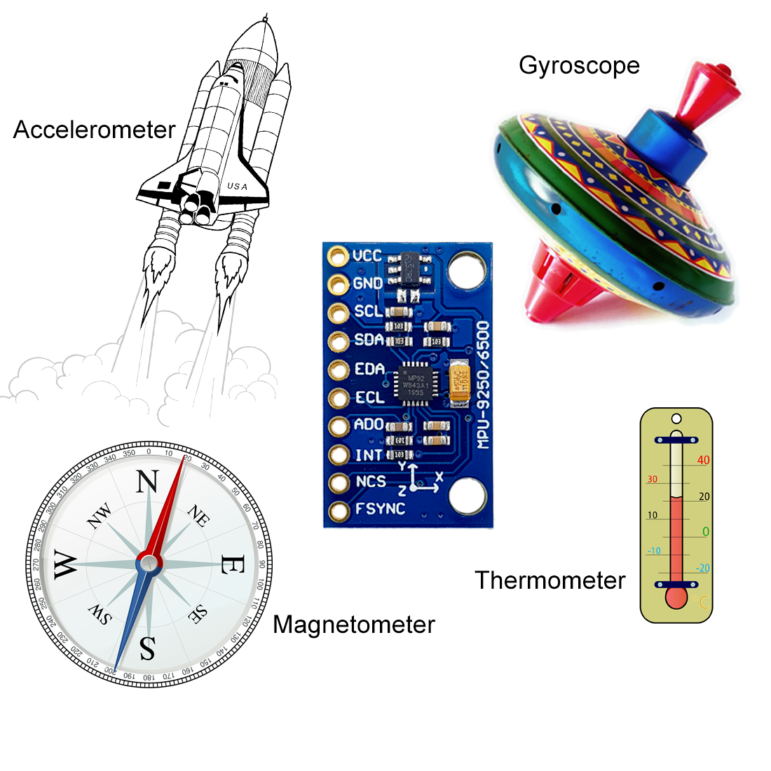
In previous articles, I have introduced the accelerometers MMA7361 and ADXL345. I also reported on the MPU6050 gyroscope and accelerometer sensor module. This time I would like to focus on the 9-axis sensor module MPU9250. It combines four functions:
- Gyroscope
- Accelerometer
- Magnetometer
- Thermometer
During my research, I was looking for a library that on the one hand implemented the many functions and setting parameters of the MPU9250, but on the other hand can be operated without having to go into the depths of the data sheet. Since I didn’t really find what I was looking for, I wrote a library myself, which I will present in this article.
Update 25th of March 2022: The library now also works with the MPU6500, which is basically an MPU9250 without a magnetometer. Moreover I have implemented SPI control. Example sketches are attached to the library.
Update 30th of July: I am getting more and more comments and e-mails that the magnetometer does not work and/or that the sketches report back “MPU9250/MPU6500 does not respond”. Please read readme on GitHub and check your module with the example sketch MPU9250_who_am_I.
Because of the size of the topic, I have decided to split the post. In this first part, I deal with:
- Features / Technical specifications of the MPU9250
- Wiring
- Introduction to my library MPU9250:
- Getting the basic data:
- Acceleration
- Gyroscope
- Magnetometer
- All basic data and temperature
- Calibration
- Getting the basic data:
In part 2, I will continue the introduction to my library:
- Measuring angles
- Set up interrupts
- Low-power / cycle mode
- Using the FIFO
Features and specifications of the MPU9250
How a gyroscope and an accelerometer works, I have already described in my article about the MPU6050. The magnetometer works based on the Hall effect. You find a good animation here.
The MPU9250 is actually a discontinued model. On the manufacturer’s pages it is marked as “EoL” (End of Life). But I assume that you can buy the modules for a few more years. On Amazon and eBay, the selection of stores that offer the MPU9250 is huge. The successor model is the ICM-20948, which I will report on soon. However, the modules are still relatively expensive (€15). You can get the MPU9250 for half the price.
Since the MPU9250 combines four sensors, a complete list of technical data would be beyond the scope. The essential key data is:
- Power supply: 3.0 – 5.0 volts (module)
- for the actual IC it is 2.4 – 3.6 volts
- Communication via I2C, the addresses are:
- AD0 unconnected or LOW: 0x68
- AD0 to HIGH: 0x69
- Communication via SPI
- Gyroscope
- Ranges: +/-250, +/-500, +/-1000, +/-2000 °/s
- Data rate: 3.91 – 32000 Hz
- Resolution: 16 bits
- Power consumption: 3.2 mA (normal mode) / 8 µA (sleep mode)
- Accelerometer:
- Ranges: +/- 2, +/-4, +/-8, +/-16 g
- Data rate: 0.24 Hz (in cycle mode) to 4000 Hz
- Resolution: 16 bits
- Power consumption: 450 µA (normal mode) / 8.4 µA in low-power mode (0.98 Hz cycle) / 19.8 µA in low-power mode (31.25 Hz cycle)
- Magnetometer:
- Measuring range: +/- 4800 µT
- Data rate: 8 Hz or 100 Hz
- Resolution: 14 or 16 bits (I only implemented 16 bit resolution)
- Power consumption: 280 A at 8 Hz data rate
- FIFO (First in, first out) data storage: 512 bytes = 256 single values = 85 x,y,z data triple
- Interrupts: FIFO Overflow, data ready and wake-on-motion (acceleration) interrupt
- Integrated thermometer
The MPU9250 allows you to control five additional sensors via I2C in a subnet, to store and read the data in the MPU9250, or store it in the FIFO. But I have only implemented that for the magnetometer.
Further information can be found in the technical data sheet, in the register map and in the data sheet of the magnetic sensor AK8963.
Control of the MPU9250 with Arduino UNO & Co
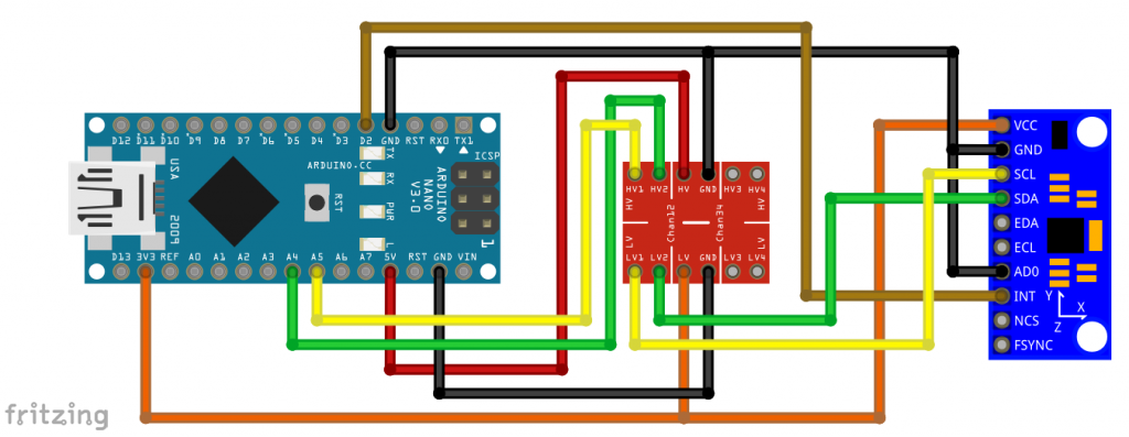
Wiring
Pull-up resistors for the I2C lines are not needed. You may need to use a level converter or voltage divider for the inputs and outputs if you are using a 5V board. Even though the MPU9250 module has a voltage regulator for VCC, this does not necessarily mean that the other inputs are also regulated down.
The connection of the interrupt pin is needed for some example ketches. Since I set it active-high, I don’t need a voltage regulator for it.
- EDA/ECL are the I2C connectors for external sensors – I have not (yet) implemented this option as mentioned
- AD0: connected to HIGH, the I2C address is changed from 0x68 to 0x69
- NCS: Chip select for SPI operation (not implemented in my library)
- FSYNC (“frame synchronization”): can be used as an interrupt input for other sensors – I have not (yet) implemented this.
Libraries for the MPU9250
There are a number of libraries available for the MPU9250. Check out the Arduino Library Manager or GitHub for this. As I mentioned at the beginning, I wasn’t happy with the available libraries, but that’s a matter of taste.
You can download my library MPU9250_WE here from GitHub or you install it directly via the Arduino IDE Library Manager.
The problem with the MPU9250 is that it has an incredible amount of setting options due to its 4 sensors plus I2C subnet control. In such cases, the question arises whether everything that is possible should be implemented. And although I didn’t, my library contains fifty-nine public features. To explain the use of these functions, I have attached eleven example sketches.
Introduction to the library MPU9250_WE
The basic data
To get to know the library and the MPU9250, I recommend trying out the sketches in the order used here. We start with the basic data for acceleration, gyroscope, magnetometer and thermometer. This is a pretty dry read! If I were you, I would get an MPU9250 and try out the example sketches in parallel in practice.
Example sketch 1: MPU9250_acceleration_data
This first sketch is the one I go into most intensively. Many functions are also used in other sketches.
First, a comment about the data format “xyzFloat”. This is a structure (struct) consisting of three float values. I use xyzFloat for all data that has an x, y, and z component.
#include <MPU9250_WE.h>
#include <Wire.h>
#define MPU9250_ADDR 0x68

/* There are several ways to create your MPU9250 object:
 * MPU9250_WE myMPU9250 = MPU9250_WE()              -> uses Wire / I2C Address = 0x68
 * MPU9250_WE myMPU9250 = MPU9250_WE(MPU9250_ADDR)  -> uses Wire / MPU9250_ADDR
 * MPU9250_WE myMPU9250 = MPU9250_WE(&wire2)        -> uses the TwoWire object wire2 / MPU9250_ADDR
 * MPU9250_WE myMPU9250 = MPU9250_WE(&wire2, MPU9250_ADDR) -> all together
 * Successfully tested with two I2C busses on an ESP32
 */
MPU9250_WE myMPU9250 = MPU9250_WE(MPU9250_ADDR);

void setup() {
  Serial.begin(115200);
  Wire.begin();
  if(!myMPU9250.init()){
    Serial.println("MPU9250 does not respond");
  }
  else{
    Serial.println("MPU9250 is connected");
  }

  /* The slope of the curve of acceleration vs measured values fits quite well to the theoretical
   * values, e.g. 16384 units/g in the +/- 2g range. But the starting point, if you position the
   * MPU9250 flat, is not necessarily 0g/0g/1g for x/y/z. The autoOffset function measures offset
   * values. It assumes your MPU9250 is positioned flat with its x,y-plane. The more you deviate
   * from this, the less accurate will be your results.
   * The function also measures the offset of the gyroscope data. The gyroscope offset does not
   * depend on the positioning.
   * This function needs to be called at the beginning since it can overwrite your settings!
   */
  Serial.println("Position you MPU9250 flat and don't move it - calibrating...");
  delay(1000);
  myMPU9250.autoOffsets();
  Serial.println("Done!");

  /*  This is a more accurate method for calibration. You have to determine the minimum and maximum
   *  raw acceleration values of the axes determined in the range +/- 2 g.
   *  You call the function as follows: setAccOffsets(xMin,xMax,yMin,yMax,zMin,zMax);
   *  Use either autoOffset or setAccOffsets, not both.
   */
  //myMPU9250.setAccOffsets(-14240.0, 18220.0, -17280.0, 15590.0, -20930.0, 12080.0);

  /*  Sample rate divider divides the output rate of the gyroscope and accelerometer.
   *  Sample rate = Internal sample rate / (1 + divider)
   *  It can only be applied if the corresponding DLPF is enabled and 0<DLPF<7!
   *  Divider is a number 0...255
   */
  myMPU9250.setSampleRateDivider(5);

  /*  MPU9250_ACC_RANGE_2G      2 g
   *  MPU9250_ACC_RANGE_4G      4 g
   *  MPU9250_ACC_RANGE_8G      8 g
   *  MPU9250_ACC_RANGE_16G    16 g
   */
  myMPU9250.setAccRange(MPU9250_ACC_RANGE_2G);

  /*  Enable/disable the digital low pass filter for the accelerometer
   *  If disabled the the bandwidth is 1.13 kHz, delay is 0.75 ms, output rate is 4 kHz
   */
  myMPU9250.enableAccDLPF(true);

  /*  Digital low pass filter (DLPF) for the accelerometer, if enabled
   *  MPU9250_DPLF_0, MPU9250_DPLF_2, ...... MPU9250_DPLF_7
   *   DLPF     Bandwidth [Hz]      Delay [ms]    Output rate [kHz]
   *     0           460               1.94           1
   *     1           184               5.80           1
   *     2            92               7.80           1
   *     3            41              11.80           1
   *     4            20              19.80           1
   *     5            10              35.70           1
   *     6             5              66.96           1
   *     7           460               1.94           1
   */
  myMPU9250.setAccDLPF(MPU9250_DLPF_6);

  /*  Set accelerometer output data rate in low power mode (cycle enabled)
   *   MPU9250_LP_ACC_ODR_0_24          0.24 Hz
   *   MPU9250_LP_ACC_ODR_0_49          0.49 Hz
   *   MPU9250_LP_ACC_ODR_0_98          0.98 Hz
   *   MPU9250_LP_ACC_ODR_1_95          1.95 Hz
   *   MPU9250_LP_ACC_ODR_3_91          3.91 Hz
   *   MPU9250_LP_ACC_ODR_7_81          7.81 Hz
   *   MPU9250_LP_ACC_ODR_15_63        15.63 Hz
   *   MPU9250_LP_ACC_ODR_31_25        31.25 Hz
   *   MPU9250_LP_ACC_ODR_62_5         62.5 Hz
   *   MPU9250_LP_ACC_ODR_125         125 Hz
   *   MPU9250_LP_ACC_ODR_250         250 Hz
   *   MPU9250_LP_ACC_ODR_500         500 Hz
   */
  //myMPU9250.setLowPowerAccDataRate(MPU9250_LP_ACC_ODR_500);

  /* sleep() sends the MPU9250 to sleep or wakes it up.
   * Please note that the gyroscope needs 35 milliseconds to wake up.
   */
  //myMPU9250.sleep(true);

 /* If cycle is set, and standby or sleep are not set, the module will cycle between
   *  sleep and taking a sample at a rate determined by setLowPowerAccDataRate().
   */
  //myMPU9250.enableCycle(true);

  /* You can enable or disable the axes for gyrometer and/or accelerometer measurements.
   * By default all axes are enabled. Parameters are:
   * MPU9250_ENABLE_XYZ  //all axes are enabled (default)
   * MPU9250_ENABLE_XY0  // X, Y enabled, Z disabled
   * MPU9250_ENABLE_X0Z
   * MPU9250_ENABLE_X00
   * MPU9250_ENABLE_0YZ
   * MPU9250_ENABLE_0Y0
   * MPU9250_ENABLE_00Z
   * MPU9250_ENABLE_000  // all axes disabled
   */
  //myMPU9250.enableAccAxes(MPU9250_ENABLE_XYZ);

}

void loop() {
  xyzFloat accRaw = myMPU9250.getAccRawValues();
  xyzFloat accCorrRaw = myMPU9250.getCorrectedAccRawValues();
  xyzFloat gValue = myMPU9250.getGValues();
  float resultantG = myMPU9250.getResultantG(gValue);

  Serial.println("Raw acceleration values (x,y,z):");
  Serial.print(accRaw.x);
  Serial.print("   ");
  Serial.print(accRaw.y);
  Serial.print("   ");
  Serial.println(accRaw.z);

  Serial.println("Corrected ('calibrated') acceleration values (x,y,z):");
  Serial.print(accCorrRaw.x);
  Serial.print("   ");
  Serial.print(accCorrRaw.y);
  Serial.print("   ");
  Serial.println(accCorrRaw.z);

  Serial.println("g values (x,y,z):");
  Serial.print(gValue.x);
  Serial.print("   ");
  Serial.print(gValue.y);
  Serial.print("   ");
  Serial.println(gValue.z);

  Serial.print("Resultant g: ");
  Serial.println(resultantG); // should always be 1 g if only gravity acts on the sensor.
  Serial.println();

  delay(1000);
}
Initialization and offsets
The function init() first performs a reset of the MPU9250 and writes default values to some registers. init() returns false if the MPU9250 should not be responsive, otherwise it returns true.
If the MPU9250 is positioned flat, i.e. horizontal x,y-plane, only the acceleration due to gravity acts on it. Accordingly, the g-values for the x- and y-axis should be zero and for the z-axis it should be one. However, these values are more or less shifted. The function autoOffset() measures the offset values which are subtracted from future measured values. The slope, on the other hand, had not to be corrected for the modules I tried out. In the 2g range, the difference between the minimum and maximum raw acceleration values was quite close to the expected 2 x 16348 (i.e. 2x 10¹⁵). autoOffset() only works reliably if:
- the module is positioned flat with its x,y-plane,
- is not moved, and
- the function is called as the first function in the setup (because it changes some settings)
Alternatively, you can use the setAccOffsets() function. It results in less good zero values, but is more accurate with larger angles, and you don’t have to position the module when the program starts.
Other settings
The function setAccRange() sets the range for the acceleration measurements.
To control the data rate, you use the function setSampleRateDivider(divider).
\text{data rate}=\frac{1}{1+divider}\;[\text{kHz}]However, this only works if the digital low pass filter (DLPF) is activated and its mode is 1 to 6. The DLPF is (de-)activated done with enableAccDLPF(true/false). You choose the level with setAccDLPF(). The higher the level, the lower the noise. Only level 7 does not fit in this series in this respect. The disadvantage of high smoothing is reduced response time. This means that when the acceleration changes, it takes a while for the MPU9250 to output the correct value. Details of these delay times can be found in the sketch.
With sleep(), you put the accelerometer and the gyroscope to sleep. However, this does not apply to the magnetometer, as it has a certain life of its own (not sure if this translates well).
If you don’t want to activate all axes, you can use enableAccAxes() to change the default setting. The parameters are explained in the sketch.
I explain the functions setCycle() and setLowPowerAccDataRate() elsewhere.
The results
You can query the measurement results with the following functions:
getAccRawValues()returns the raw values of acceleration as they are in the MPU9250 data registersgetCorrectedAccRawValues()reads the raw values and corrects them by the offsetsgetGValues()returns the acceleration values in g (based on the corrected raw data)getResultantG(gValue)calculates the resulting acceleration from a g-value triple, i.e. the magnitude of the sum of the three vectors
\text{resultantG}=\sqrt{(gValue.x)^2+(gValue.y)^2+(gValue.z)^2} \;\;\text{[g]}If only gravity affects the MPU9250, the resultant should always be 1. With the resultant function, you can easily measure accelerations without having to align the movement to an axis. Simply subtract 1 to exclude the earth’s acceleration.
The output of MPU9250_acceleration_data.ino
And this is the output on the serial monitor:

Example sketch 2: MPU9250_gyroscope_data
Since you already know some functions, the explanation of the gyroscope functions can be much shorter.
#include <MPU9250_WE.h>
#include <Wire.h>
#define MPU9250_ADDR 0x68

/* There are several ways to create your MPU9250 object:
 * MPU9250_WE myMPU9250 = MPU9250_WE()              -> uses Wire / I2C Address = 0x68
 * MPU9250_WE myMPU9250 = MPU9250_WE(MPU9250_ADDR)  -> uses Wire / MPU9250_ADDR
 * MPU9250_WE myMPU9250 = MPU9250_WE(&wire2)        -> uses the TwoWire object wire2 / MPU9250_ADDR
 * MPU9250_WE myMPU9250 = MPU9250_WE(&wire2, MPU9250_ADDR) -> all together
 * Successfully tested with two I2C busses on an ESP32
 */
MPU9250_WE myMPU9250 = MPU9250_WE(MPU9250_ADDR);

void setup() {
  Serial.begin(115200);
  Wire.begin();
  if(!myMPU9250.init()){
    Serial.println("MPU9250 does not respond");
  }
  else{
    Serial.println("MPU9250 is connected");
  }

  /* The slope of the curve of acceleration vs measured values fits quite well to the theoretical
   * values, e.g. 16384 units/g in the +/- 2g range. But the starting point, if you position the
   * MPU9250 flat, is not necessarily 0g/0g/1g for x/y/z. The autoOffset function measures offset
   * values. It assumes your MPU9250 is positioned flat with its x,y-plane. The more you deviate
   * from this, the less accurate will be your results.
   * The function also measures the offset of the gyroscope data. The gyroscope offset does not
   * depend on the positioning.
   * This function needs to be called at the beginning since it can overwrite your settings!
   */
  Serial.println("Position you MPU9250 flat and don't move it - calibrating...");
  delay(1000);
  myMPU9250.autoOffsets();
  Serial.println("Done!");

  /*  The gyroscope data is not zero, even if you don't move the MPU9250.
   *  To start at zero, you can apply offset values. These are the gyroscope raw values you obtain
   *  using the +/- 250 degrees/s range.
   *  Use either autoOffset or setGyrOffsets, not both.
   */
  //myMPU9250.setGyrOffsets(45.0, 145.0, -105.0);

 /*  You can enable or disable the digital low pass filter (DLPF). If you disable the DLPF, you
   *  need to select the bandwidth, which can be either 8800 or 3600 Hz. 8800 Hz has a shorter delay,
   *  but higher noise level. If DLPF is disabled, the output rate is 32 kHz.
   *  MPU9250_BW_WO_DLPF_3600
   *  MPU9250_BW_WO_DLPF_8800
   */
  myMPU9250.enableGyrDLPF();
  //myMPU9250.disableGyrDLPF(MPU9250_BW_WO_DLPF_8800); // bandwidth without DLPF

  /*  Digital Low Pass Filter for the gyroscope must be enabled to choose the level.
   *  MPU9250_DPLF_0, MPU9250_DPLF_2, ...... MPU9250_DPLF_7
   *
   *  DLPF    Bandwidth [Hz]   Delay [ms]   Output Rate [kHz]
   *    0         250            0.97             8
   *    1         184            2.9              1
   *    2          92            3.9              1
   *    3          41            5.9              1
   *    4          20            9.9              1
   *    5          10           17.85             1
   *    6           5           33.48             1
   *    7        3600            0.17             8
   *
   *    You achieve lowest noise using level 6
   */
  myMPU9250.setGyrDLPF(MPU9250_DLPF_6);

  /*  Sample rate divider divides the output rate of the gyroscope and accelerometer.
   *  Sample rate = Internal sample rate / (1 + divider)
   *  It can only be applied if the corresponding DLPF is enabled and 0<DLPF<7!
   *  Divider is a number 0...255
   */
  myMPU9250.setSampleRateDivider(99);


  /*  MPU9250_GYRO_RANGE_250       250 degrees per second (default)
   *  MPU9250_GYRO_RANGE_500       500 degrees per second
   *  MPU9250_GYRO_RANGE_1000     1000 degrees per second
   *  MPU9250_GYRO_RANGE_2000     2000 degrees per second
   */
  myMPU9250.setGyrRange(MPU9250_GYRO_RANGE_250);

  /* sleep() sends the MPU9250 to sleep or wakes it up.
   * Please note that the gyroscope needs 35 milliseconds to wake up.
   */
  //myMPU9250.sleep(true);

  /* This is a low power standby mode for the gyro function, which allows quick enabling.
   * (see data sheet for further information)
   */
  //myMPU9250.enableGyrStandby(true);


  /* You can enable or disable the axes for gyroscope and/or accelerometer measurements.
   * By default all axes are enabled. Parameters are:
   * MPU9250_ENABLE_XYZ  //all axes are enabled (default)
   * MPU9250_ENABLE_XY0  // X, Y enabled, Z disabled
   * MPU9250_ENABLE_X0Z
   * MPU9250_ENABLE_X00
   * MPU9250_ENABLE_0YZ
   * MPU9250_ENABLE_0Y0
   * MPU9250_ENABLE_00Z
   * MPU9250_ENABLE_000  // all axes disabled
   */
  //myMPU9250.enableGyrAxes(MPU9250_ENABLE_000);
}

void loop() {
  xyzFloat gyrRaw = myMPU9250.getGyrRawValues();
  xyzFloat corrGyrRaw = myMPU9250.getCorrectedGyrRawValues();
  xyzFloat gyr = myMPU9250.getGyrValues();

  Serial.println("Gyroscope raw values (x,y,z):");
  Serial.print(gyrRaw.x);
  Serial.print("   ");
  Serial.print(gyrRaw.y);
  Serial.print("   ");
  Serial.println(gyrRaw.z);

  Serial.println("Corrected gyroscope raw values (x,y,z):");
  Serial.print(corrGyrRaw.x);
  Serial.print("   ");
  Serial.print(corrGyrRaw.y);
  Serial.print("   ");
  Serial.println(corrGyrRaw.z);

  Serial.println("Gyroscope Data in degrees/s (x,y,z):");
  Serial.print(gyr.x);
  Serial.print("   ");
  Serial.print(gyr.y);
  Serial.print("   ");
  Serial.println(gyr.z);

  Serial.println("*********************************");

  delay(1000);
}
The setting options for the gyroscope
Again, you can use the autoOffsets() function. The gyroscope should return zero for all axes in the non-moving state, or at least fluctuate around zero. However, you will notice some offset that is independent of the positioning (tilt). Alternatively, use the values determined in the +/-250 °/s measuring range for setGyrOffsets(). I’ll come back to that when we talk about the calibration sketch.
You activate the low-pass filter (DLPF) with enableGyrDLPF(). If you disable the DLPF, you can still choose between the two bandwidths 8800 and 3600 Hz. Therefore, you have to pass the corresponding parameters to the disableGyrDLPF() function. You choose the level of the low-pass filter with setGyrDLPF(). Here, too, a stronger filter leads to greater delays. Similarly, level 7 does not fit in the series. Level 6 provides the lowest noise.
Other features:
setSampleRateDivider()works like the accelerometersetGyrRange()sets the rangeenableGyrStandby()sends the gyroscope into a kind of half-sleep, which allows a faster wake-up than from sleep mode (unfortunately I didn’t find concrete data)enableGyrAxes()activates or deactivates the axesgetGyrRawValues()provides the currently available raw datagetCorrectedGyrRawValues()subtracts the offsets from the raw data and provides the corrected datagetGyrValues()provides the gyroscope data in degrees/second, based on the corrected raw data
Output of MPU9250_gyroscope_data.ino
The first values in the output below were determined without moving the MPU9250. For the second set of values, I rotated the module around its x-axis.

Example sketch 3: MPU9250_magnetometer_data.ino
The magnetometer (AK8963) behaves like a separate device. It has its own I2C address (0x0C) and own registers. Thus, it has to be initialized separately. If you check the MPU9250 with an I2C scanner, it will only detect the MPU9250 address. The magnetometer is not directly accessible behind the MPU9250. It is controlled via a kind of I2C subnet which is provided by the MPU9250. However, you won’t notice that complexity since the library manages all that in the background.
#include <MPU9250_WE.h>
#include <Wire.h>
#define MPU9250_ADDR 0x68

/* There are several ways to create your MPU9250 object:
 * MPU9250_WE myMPU9250 = MPU9250_WE()              -> uses Wire / I2C Address = 0x68
 * MPU9250_WE myMPU9250 = MPU9250_WE(MPU9250_ADDR)  -> uses Wire / MPU9250_ADDR
 * MPU9250_WE myMPU9250 = MPU9250_WE(&wire2)        -> uses the TwoWire object wire2 / MPU9250_ADDR
 * MPU9250_WE myMPU9250 = MPU9250_WE(&wire2, MPU9250_ADDR) -> all together
 * Successfully tested with two I2C busses on an ESP32
 */
MPU9250_WE myMPU9250 = MPU9250_WE(MPU9250_ADDR);

void setup() {
  Serial.begin(115200);
  Wire.begin();
  if(!myMPU9250.init()){
    Serial.println("MPU9250 does not respond");
  }
  else{
    Serial.println("MPU9250 is connected");
  }
  if(!myMPU9250.initMagnetometer()){
    Serial.println("Magnetometer does not respond");
  }
  else{
    Serial.println("Magnetometer is connected");
  }

  /* You can choose the following operational modes
   * AK8963_PWR_DOWN            power down (default)
   * AK8963_CONT_MODE_8HZ       continuous at 8Hz sample rate
   * AK8963_CONT_MODE_100HZ     continuous at 100Hz sample rate
   *
   * In trigger mode the AK8963 goes into power down after the measurement
   */
  myMPU9250.setMagOpMode(AK8963_CONT_MODE_100HZ);

  /* In continuous mode you need to wait for the first data to be available. If you
   * comment the line below you will probably obtain zero.
   */
  delay(200);
}

void loop() {
  xyzFloat magValue = myMPU9250.getMagValues(); // returns magnetic flux density [µT]

  Serial.println("Magnetometer Data in µTesla: ");
  Serial.print(magValue.x);
  Serial.print("   ");
  Serial.print(magValue.y);
  Serial.print("   ");
  Serial.println(magValue.z);

  delay(1000);
}
The settings for the magnetometer
The magnetometer has a power-down mode and two continuous modes. The continuous modes differ in the data rate, namely 8 or 100 Hz. You’re setting the mode with setMagOpMode().
You can query magnetometer values with getMagValues(). The result is output in microtesla. The function returns the values that are currently in the data store. In 8 Hz mode the data can be up to 125 ms “old”. Accordingly, after initialization the first value could be zero. To avoid that I have added a delay().
Output of MPU9250_magnetometer_data.ino
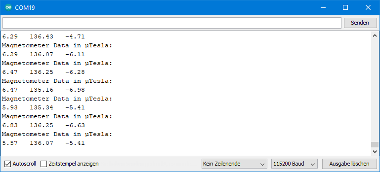
The results were a little sobering at first. I expected to be able to use the MPU9250 as a compass without any problems.
In Central Europe, the magnetic flux density of the Earth’s magnetic field is about 20 microns in the horizontal and around 44 µT in the vertical (source: German Wikipedia). Accordingly, the difference between the maximum and minimum values when rotating the module horizontally and vertically should be 40 and 88 micrometers, respectively. You, like me, probably won’t measure that because:
- Again, there are offsets.
- You are probably measuring inside, and depending on the design of the house, the geomagnetic field is shielded.
- When measuring on the breadboard, the jumper cables and metal inside the breadboard can influence the measurements.
I had also played around with strong magnets and magnetized my breadboard. Only when connecting with jumper cables only from below and without breadboard the results made more sense.
I haven’t (yet) pursued using the magnetometer as a compass. According to what I have read in other articles for other magnetometers, this seems to be a science in itself. At least if you don’t just want to find north and south.
Example sketch 4: MPU9250_all_data.ino
This sketch provides acceleration, gyroscope data, magnetometer data and the temperature. You query the temperature with getTemperature(). The other functions have been introduced before. You find the sketch in the examples.
The thermometer is not really to measure the ambient temperature. It is more to control the temperature within the MPU9250. It is higher than the ambient temperature and rises dependent on the parameters you set.
Setting offsets permanently
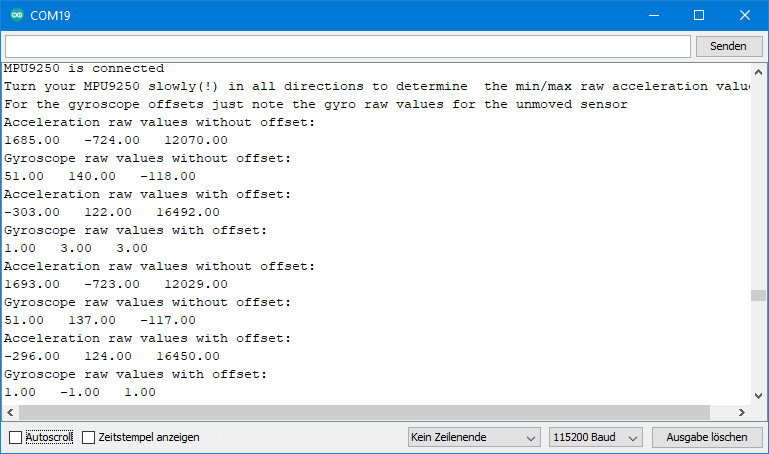
Example sketch 5: MPU9250_calibration
This sketch is designed to help you determine the offsets for the accelerometer and gyroscope. For this purpose, the lowest measuring range and the maximum low-pass filter are set first. This ensures high resolution and low noise.
For the offset determination of the accelerometer, you turn the MPU9250 slowly (!) around its axes and note the maximum and minimum raw values. It is best to have your elbows on the table when doing this, as any shaking will result in additional acceleration. You then use this data for the setAccOffsets() function. Internally, the offsets are determined from this. When you change the measuring range, the offsets are automatically adjusted. With this method, you no longer need to position the MPU9250 flat when starting the program. However, I would still recommend the function autoOffsets() to determine precise small tilt angles precisely.
For the gyroscope offsets you don’t have to rotate the MPU9250 because the offset is independent of the inclination. You take the values for the x-, y- and z-axis as parameters in setGyrOffsets().
You can find the sketch in the examples. I don’t show it here.
Output of MPU9250_calibration.ino
Update 2024: Reusing autoOffsets() data
I have added the functions getAccOffsets() and getGyrOffsets(), with which you can query the calibration data of the autoOffset() function. This means you don’t have to run autoOffset() every time you start the program. The example sketch MPU9250_reusing_autocalib_data.ino shows how it works.
Outlook
The second part of the article is about angles, interrupts, the low-power mode and the FIFO buffer. Of course, you don’t have to wait since you can try the example sketches now.
Acknowledgement
I found the MPU9250 as a Fritzing component here – thanks to Randy!
I found the parts for the post picture as usual on Pixabay. The compass, the space shuttle and the thermometer are taken from OpenClipart-Vectors. The gyro is from InspiredImages (Anthony).
Hi, I would like to know why my magnetometer gives me a value of 0 in the three axis, mx = 0, my = 0 and mz = 0.
Other question is How can I get the Yaw angle? Because I want to use that value for my UGV, to fix the position in the path that It has to follow.
Hi, maybe your MPU9250 is not an MPU9250 but an MPU6500. Please try the “Who am I” example sketch an read the read.me:
https://github.com/wollewald/MPU9250_WE
If this is not the issue then please provide some details (which MCU Board, I2C or SPI, etc).
Regarding the yaw angle there are two options, both with some issues.
1) Use the magnetometer. You would need to determine the min/max values and then you interpolate the values in between. But the measured values can vary dependend on the location.
2) Measure the gyroscope values in high frequency. Angle/time * time = angle. This is not the most reliable method of course. Differences will add up over time.
Regards, Wolfgang
Hi, firstly, excellent work on the creation of this library.
Do you have an example of how to apply the FFT to the accelerometer’s data output? I’m using your library with the active DPLF (1kHz rate output) to measure the vibration of an industrial motor, but I can’t find the correct fundamental frequency.
Thanks for your help.
Hi, you mean FFT = Fast Fourier Transformation? It’s been almost 30 years now since I’ve looked into Fourier transformations. I still know roughly what it is about, but I am far from being able to apply it. Sorry!
Thanks anyway 🙂
Hello,
Thanks for the library and the posts. I have a question about the ‘MPU9250_magnetometer_data.ino’ sketch. From the MPU9250 datasheet, it is seen that the axes of the IMU (Acc+Gyro) and Magnetometer are different. Does the sketch return mag field values in the magnetometer axes or have they been transformed to the IMU axes?
Hi, I didn’t change any axis. That means all x values are taken from the x registers, y-values from y-registers and z-values from z-registers.
Hi,
I would like to connect one more sensor via SPI to read the values, but the problem is that I can’t write the second pick chip. Can you help me with this somehow? Thank you for your reply.
Hi, I tried 3 different MPU9250, but they all fail the who_am_I test although MP92 is writtent on the chip.
who am I result is 0x70 or 0x75.
I have all acc, gyr and temps values but magnetometer is always stuck to zero.
Please advise.
Hi, in the register map of the MPU9250 (https://invensense.tdk.com/wp-content/uploads/2015/02/RM-MPU-9250A-00-v1.6.pdf) you find on page 44, that the Who am I register should contain the value 0x71.
The register map of the MPU6500 (https://invensense.tdk.com/wp-content/uploads/2015/02/MPU-6500-Register-Map2.pdf) clearly says on page 44 that its Who Am I register value is 0x70.
For the MPU6515 I haven’t found a register map. The information that its Who am I register should contain 0x75 is something I found here:
https://android.googlesource.com/kernel/mediatek/+/android-mtk-3.18/drivers/misc/mediatek/gyroscope/mpu6515/mpu6515.h
To me, this seems to be a new dimension of fake. I have seen non-labelled MPUxxxx but I haven’t seen any with a mismatch of label and Who am I register. I would send the modules back to the supplier and try from a different source.
Thanks for your reply. I will try to send it (them) back.
I already tried different shops and they all seem to have their breed of fake.
Do you know of a site and reference where we can find good MPU9250 for sure ?
Best regards.
Hi, I ordered three times from different shops on Amazon. Two deliveries were OK, the other was MPU6500 based modules. Unfortunately the shops that delivered real MPU9250 modules do not have them anymore. It seems the number of wrong modules is increasing. Maybe it’s because the MPU9250 is marked as “End of Life” by TDK, so not sure if the chip is still being produced somewhere.
Iwould search on Amazon and ebay and have a look at the comments from other customers. You could also ask the vendor in advance if he can assure that you will get an MPU9250 based module.
Good luck!
Hi, not sure if you are still interested, but I just received real MPU9250 modules from this source:
Update: I have deleted the link. I have ordered again and received fake MPU9250. Correct label on the IC (MP92), but wrong value in the Who Am I register: 0x70 = MPU6500. Very disappointing!
thanks. i ordered some. 🤞
I hope they have some good left for you!!!
Hi,
thank you very much for the article, really interesting.
I also experienced the same issue of Patrice: from Amazon two vendors sold me board with WHO_AM_I 0x70 instead of the 0x71 you mentioned before.
Following your advice, I clicked on https://de.aliexpress.com/item/1005005378436815.html?spm=a2g0o.productlist.main.5.11303b5foovnJe&algo_pvid=f4d15f33-484e-4926-8eda-534d187b7dfd&algo_exp_id=f4d15f33-484e-4926-8eda-534d187b7dfd-2&pdp_npi=3%40dis%21EUR%214.9%214.16%21%21%21%21%21%40211bf3f816825286702212966d07dd%2112000032807873910%21sea%21DE%21897358883&curPageLogUid=Uw6tMWs1OP0j but I noticed in the specifications that the sensor is actually an MPU6050. Was it the same a couple of weeks ago, or did they change the description?
Thank you,
Gabriele
Hi Gabriele, yes, the description for the MPU9250 at this shop is misleading. You can choose there between an MPU9250 and an MPU6500. But the description always says “MPU6500”. I can only say I chose MPU9250 and I received MPU9250. Of course I can give a guarantee!
Than you very much! I will follow your advice.
Gabriele
Hi,
I have the same issue of Patrice. Both the MPU9250 sensors I bought from the suggested source have the WHO_AM_I set to 0x70.
So sad about that. I will open a dispute with the vendor as Patrice did, and I would be grateful if you would suggest a reliable source to find the MPU9250 we all need.
Thank you,
Gabriele
Hi Gabriele,
since I had recommended that source I ordered once again – and received MPU6500 modules. They have even the even the label MP92 on the IC, which is the correct label for the MPU9250. This is another level of fake. I have written a review on AliExpress to warn other people. I am very embarrassed that I recommeded that shop, although I pointed out that I can’t give a guarantuee. Now I am also clueless where to get real MPU9250 modules from. I am going to try MPU9255 modules which should work similar like MPU9250 modules. Maybe this is more reliable. I ordered from three shops and await the delivery in few weeks. So before you try the same, let me see first what I get.
And, btw. Patrice sent me one of his bad modules and I can confirm that thes are definitely MPU6500.
Cheers, Wolfgang
Hi, I finnaly got the time to test the ones I ordered from your shop… and… same answer again “WhoAmI Register: 0x70” :-(.
I also opened a dispute with some other former vendor about this, I instisted heavily, but according to them, components are ok.
I now have 5 of those from different vendors and none seam to have compas… how can that be ??? can it be that I am doing something wrong ? I did the exact same diagram you exposed above. please give me hope 😉
Really strange – and disappointing also for me since I recommended the shop. If you did something wrong I would expect that nothing would work. I am happy to look at one of the modules you received if you send it to me. Are you from France? Then it’s affordable. I would also send you one that is working. We can exchange addresses via e-mail if you are interested.
With pleasure. Can you initiate a mail to me as I don’t find your email. thanks.
I order again from the source I recommended and received fake MPU9250. Shit! Very disappointing. It seems there is no reliable source anymore.
Thank you so much for writing these 2 articles! They are the most comprehensive that I have found.
I am trying to find information about setting up the ECL/EDA ADO & FSYNC. Does this chip just work as an additional i2c bus, because of the 3 sensors on board, allowing you to connect additional i2c devices? If so, how do you acces those additional sensors?
I was considering using the C code connecting to the device and doing the calculations as a background process on Linux so I could acces the /dev files when I need info OR setting output to a file that’s cache. Would the FSYNC interrupt be something that could be utilized to signal when certain conditions occur?
Thanks in advance for your responses!
Hi Chris,
only the gyroscope and the accelerometer data is directly accessible via I2C or SPI. The magnetometer is a chip in the chip with separate I2C address. To access the magnetometer, the MPU9250 uses an auxiliary I2C bus. The MPU9250 acts as a master and you can add 5 slaves. Since one of them is the magnetometer, you can add four additional ones and use the ECL/EDA pins to connect them. There are dedicated registers in the MPU9250 to which the slaves can write their data, and from these registers you can read the values. It took me quite some time to get this set up for the magnetometer, and I have stopped there.
You will have to look in the data sheet and the register map of the MPU9250. What might also help you is to look into my library files and follow the functions which are called when the magnetometer is initialized. It took at least me many hours to understand the auxiliary I2C bus and get it running.
Hope this helps a bit!
which pins should i connect to which in arduino uno i have till now connected vcc to 5v and gnd to gnd.
While i have connected the SCL pin to A5 and SDA pin to A4. and the readings i am getting in the serial monitor is some garbage data. Although I am getting it in some intervals. I also wanted to check whether my module is working or not please I need some help as I have to submit these project within these month
Connect also AD0 to GND. The rest is OK. Then please upload the example sketch MPU9250_all_data. What do you see on the Serial Monitor? Do you get the messages: “MPU9250 is connected” and “Magnetometer is connected”. Or: “MPU9250 does not respond” and “Magnetometer does not respond”?
If MPU9250 is not connected, then check the I2C Address with a scanner sketch (same circuit):
https://wolles-elektronikkiste.de/en/i2c-scanner?lang=en
If you get a different I2C address than you have applied, change it.
One additional hint: The MPU9250 uses 2.4 – 3.6 volts. Usually, the module have a voltage regulator, so you can apply 5 volts. But the I2C lines are usually not regulated (Adafruit modules are one of the few exceptions). This is why I added a level shifter in my circuit. If you don’t use a shifter, you apply 5 volts to the SDA and SCL pin of the MPU9250. Usually, you won’t destroy the MPU9250, but it can limit its lifetime. But I doubt that this is related with the problem you experience.
Hi
Your work on MPU9250 is superb! With very little experience in electronics I have manged to get the accelerometer working.
I have a MPU2950 connected to ESP32 and would like to read acceleration values precisely at 50 milliseconds (worst case 100ms). The ESP32 is also connected to and SD card module for storage of the timestamp and accelerations. Using the millis() function the time difference in the main loop is varying a lot (33ms to 40ms). Is there a way i can get a stable interval ?
Any solutions or advice will be much appreciated.
Many thanks
Paul Okoth
Hi Paul, if you have such huge deviations or fluctuations in timing then there must be a blocker somewhere. For SD-Cards I know that opening files can take quite some time. So, you should leave the file open. I am more surprised about the fluctuation than the deviation.
However, working with interrupts might help. You could adjust the data rate using the sample rate divider and use the data ready interrupt (part 2 of this article) to tell your microcontroller that it’s time to read the next value. Maybe you try this?
Good luck!
Wolfgang
Hi
You were right! I was opening the SD-Card file and closing it after every read. I opened the file once ensuring that the flush() method is called after every write. This has given a better time interval deviating by 1 millisecond (50, 50, 50, 49, 50, 51 ). I will also try the option of using the interrupt because the data will be published to an MQTT broker which may cause some blocking.
Thanks again.
Paul
Hii , In which all pins did you connect your MPU to Esp32?
Hi,
if you want to use I2C, then SDA is GPIO21 and SCL is GPIO22, AD0 should be connected to GND. If you have a module with a voltage regulator, VCC should be connected to 5V, and GND, of course, to GND. If you use the interrupt function, then you can take e.g. GPIO16 or GPIO17.
In case you are using SPI, then connect SCL (=SCLK) to GPIO18, SDA (=MOSI) to GPIO23, AD0 (=MISO) to GPIO19 and NCS (=Chip Select) to GPIO5. Power supply and interrupt pin as above for I2C.
Hi,
I am getting the following compilation errors. I am new to Arduino Uno programming. Could you help me to fix this compilation errors?
C:\Users\ramgk\OneDrive\Documents\Arduino\libraries\Bolder_Flight_Systems_Eigen\src/Eigen/Core:50:10: fatal error: complex: No such file or directory
#include
^~~~~~~~~
compilation terminated.
Hi, you have also opened an issue on GitHub for this. I prefer to not have 2 discussions. Let us continue on GitHub and not here.
For the benefit of other readers: something is messed up with another library (Bolderflight). Interested people can follow the conversation on GitHub.
Hi, what is function about int0, im using ESP32 and this board don’t have int0 by default.
Please let me know if this pin is important or can bypass.
Thanks
Hi, int0 is an interrupt pin. I explain the functions that use this pin in part 2 of this article:
https://wolles-elektronikkiste.de/en/mpu9250-9-axis-sensor-module-part-2
If you just want to obtain the data from the sensors of the MPU9250, it is not needed.
Hi , can you explain if this interruption is a pulse from MPU9250 or how we considered this value in this interrupt pin?.
It’s a signal from the MPU9250. Please read part 2 of the article to see how to use the interrupt functions of the library:
https://wolles-elektronikkiste.de/en/mpu9250-9-axis-sensor-module-part-2
Thank you! I am building an auto-pilot for my two-seater airplane (IBIS ‘Magic’). $5,000 or more for commercial, or $200 for Arduino parts? No contest!! How am I doing? “Altitude hold” is virtually complete (with BMP280) and flies the plane nicely (but doesn’t steer yet). So, now for heading hold, with 9250, gyro to deal with roll turbulence, accel to obtain ‘balanced flight’ (resultant force always perpendicular to the wing ‘plane’ while banked into the turn, and magnetometer to provide heading control. Your library gets me almost there. Now I have to do the compass bit!!! Can you help me please with the references you found most helpful (but not helpful enough, perhaps?).
Warmly, Peter
Hi Peter,
as I have pointed out in the article, I was able to get the magnetometer values from the module but struggled with calibration and to make a compass from it. This is maybe something for forums for such kind of airplanes. What I know is that people combine the values of the sensors to control airplanes.aybe this helps as a starting point:
https://github.com/kriswiner/MPU9250/blob/master/quaternionFilters.ino
Good luck, Wolfgang
After running the code it is showing magnetometer is not responding and later on, it started reading with larger fluctuations like – 1563 to -2550 so can u help solve this in the i2c … please we have important work ……..
Hi, difficult to say what the issue could be. Have you tried one of my example sketches as is, or have you modified it? The fluctuation is strange but values themselves are also strange as they are much bigger than what you usually measure.
Maybe you also try another library, like:
https://github.com/bolderflight/mpu9250
Does this work?
And what is written on the MPU9250 IC (the square IC on the module with the 24 pins)? It can be hard to read.
And do you have a drawing of your circuit and/or a photo? Then you can send it to wolfgang.ewald@wolles-elektronikkiste.de. The more information I have the better I can (hopefully) help.
I haven’t used a level shifter for this is n’t the issue Ewald?
I know the maximum flux density rate is 4912 to -4912 is an 8-bit high bit but a bit confused can u help me where the mistake I have done..
I don’t think it’s related with the level shifter. Thanks for the photo. I replied more in detail to your e-mail.
thank you for your help Ewald..
For accelerometer raw readings dividing by 16384 gives the acceleration on any particular axis in g.
How do you get gyroscope readings in deg/s from raw readings of the gyroscore?
To be exact, accelerometer raw readings dividing by 16384 only give the g-value if the range is +/-2g.
All the raw data registers have a range from -2^15 to -2^15. So, if the range you have chosen for the gyroscope is +/-250 deg/s, then a raw value of +32768 equals 250 deg/s. If you choose the +/-500 deg/s range, then 32768 equals 500 deg/s. I.e. GyrValue = Range * RawValue/32768.
Hello
I have modified your library to use SPI. Most of it works but the Magnetometer is just sending Zeros for magnetometer values even though it can send its WHO AM I MAG Nummber and seems to be connected.
Do you have a clue on what’s the problem here?
Can I send you the modified Zip of your library? if yes where can I send it?
best Regards Fabio Savi
Hi Fabio,
appreciate your support! I had also tried to implement SPI myself, but at the end I had similar issues. After spending several hours I put it back on the pile of to-do things. This is strange because I had no problem to implement SPI in my library for the ICM-20948 which has a comparable architecture. So let me check once again. Can you send the files to wolfgang.ewald@wolles-elektronikkiste.de? I will have a look, but it may take a bit until I deep-dive into it. I’ll do my best.
Regards, Wolfgang
Thanks I have sent you the files. If you did not recive them pls reply.
Hi Wolfgang!
Has the Magnetometer problem been resolved?
Regards, Gery
Hi Gery,
meanwhile I have implemented SPI for the library and the magnetometer is working fine with it.
Regards, Wolfgang
I have version 1.2.2 but the magnetometer doesn’t work. It reads “0” in all directions.
If you apply one of the example sketches, do you get the message:
MPU9250 does not respond
or:
MPU9250 is connected?
In the first rows I get this messages:
MPU9250 does not respond
Magnetometer does not respond
Position you MPU9250 flat and don’t move it – calibrating…
Done!
But after it I get the acceleration and gyro values. The values seems correct.
Then I am quite sure that you don’t have an MPU9250. It might be an MPU6500. The modules look the same and the only difference is that the MPU6500 does not have a magnetometer. You can try an MPU6500 example sketch. If it tells you that it is connected, then you know it is an MPU6500. You can also check the label on the IC itself (if there is a label). If it is an MPU9250, the label should be MP92 and if it is a MPU6500 you should find a MP62. But it’s really small and there also unlabelled ICs out there.
Yes, it is the problem.
I looked under a magnifying glass, and i realised that there is a MPU 6515. (There is an M651 label on the IC.)
Thanks for the help.
greetings. you made a very nice documentation for a very nice library and i got it working very fast. I have a relatively offtopic question mainly to serve as advice:
I’m trying to use Arduino Mega 2560 pro board and MPU9250 to sense the swinging speed of a childrens swing and display the output on adjustable lighting. the faster the swing, the brighter the light.
Do you think the output rate of mpu9250 is enough to sense and output this movement? Are there any changes in the default MPU9250_acceleration_data setup values i should look out for regarding sample rates and dividers?
Regarding the mpu9250 I tried to check the technical sheets but couldnt decide on mounting style, so I settled with the yellow chip on the side of the board facing forward, and that gave smooth values on “Corrected (‘calibrated’) acceleration value: Z” somehow….
Finally I really liked the resultantG function which I believe gives me what I need but does not seem to be sensitive enough, moving slightly between 0.92 and 1.16.
Hi, what a nice idea! The output rate will be high enough, the sensitvity is another question. The advantage of the resultantG function is that you are independend from the direction. The alternative would be to only observe one axis. I would simply try. 0.92 to 1.16 does not sound much. On the other hand you can’t expect too much acceleration. For example 0g is something you would measure when the children fall off the swing.
thank you very much for your reply. So far acceleration values z, accCorrRaw.z seems to work best for some reason. resultantG is nice however it also gives values when the sensor is not moving but just tilted after calibration as well, so not sure about it. resultantG is a great option for a swing with a single rope maybe.
I still would like to receive highest output rate levels possible because maybe its better if i smooth the values received from the sensor myself, maybe using the “Smoothed” library:
There seems to be a relationship between setSampleRateDivider (which i’m tempted to set to “1” or “2” instead of “5” and the digital low pass filter settings enableAccDLPF and setAccDLPF but I couldnt understand fully, can we confirm?
From what I understand, a higher rate can be achieved by:
DLPF is activated
myMPU9250.enableAccDLPF(true);
and setSampleRateDivider(5)is set to a higher value maybe: setSampleRateDivider(2)
or DLPF is deactivated
enableAccDLPF(false) and
and setAccDLPF(MPU9250_DLPF_6) is set to a higher value 3 with myMPU9250.setAccDLPF(MPU9250_DLPF_3);
did i understand correctly?
The acceleration sample rate is 4 kHz if you disable DLPF, if you enable it is 1 kHz. So, for a high rate output rate you should choose enableAccDLPF(false). The sample rate divider does what its name suggests, it divides the output rate. That means, for a high output rate you need the divider should be 1 – setSampleRateDivider(1). With these two setting you set an output rate of 4 kHz.
Unfortunately that doesn’t mean you can read the data in this frequency. The first bottleneck is the I2C connection. Usually it runs with a frequency of 100 kHz. This sounds a lot, but if you consider that only 1 bit at a time can be transferred you won’t be able to read the data at the output rate. You can increase the I2C speed with Wire.setClock(400000), which means 400 kHz. I still have the implementation of SPI on my to-do-list. With this the reading is much faster.
Other bottlenecks could be in your code. Between the readings you shouldn’t apply slow functions such as Serial.print.
Thank you Wolfgang, you have reviewed both mpu6050 and mpu9250, but did you get a chance to compare the features of the two?
The most obvious difference is the magnetometer which the MPU6050 does not have. If you just use the accelerometer and the gyroscope I think both are OK, but the MPU9250 has a higher data rate. What I don’t like so much about the MPU6050 is its bad documentation of registers. It’s difficult to use its full potential. That’s why I wrote a library for the MPU9250 and not for the MPU6050. And therefore I can tell you much more details about the MPU9250 than about the MPU6050.
https://www.reddit.com/r/FastLED/comments/u8q5oe/childrens_swing_with_fastled/
hi Wolfgang, here is the final project i did with the help of your library. I consider it a success , thank you 🙂 Though sensing the speed of a swing turned out rather too difficult for me especially with a rope swing and tilts of the swing seat. Will try to work further on it.
Hi, I suggest you take the resultantG and subtract 1 g. Then you get the resulting acceleration that acts on the sensor without acceleration from earth’s gravity. Calculating the acceleration without gravity only for one axis is difficult since you need to know the angle of the axis vs the horizontal. And this is a problem, when the sensor is moving. If the orientation of your z-axis is exactly vertical, then you can just subtract 1g from the z-acceleration. If not, then it’s 1g multiplied by sine(angle). Hope that helps. Best wishes, Wolfgang
Hi,
first of all great work. I use your library to my university project and I can not do this magic with sensor by my self. Can you please tell me, is here some option to remove 1g from the axes which is vertical? I measure the z axis acceleration but it could be crooked and I think that deduct 1g is not accurate.
Im sorry for my english, I search lot of on google translator, so I dont know if you completely understand me :D.
Regards,
Daniel Kupec