About this post
In my last post, I covered the basics of MicroPython. I showed how to install uPyCraft and Thonny and how to upload programs to the ESP32. However, I have only briefly discussed how you control the many functions of the ESP32 with MicroPython. I now want to close this gap. In particular, I will highlight the differences to Arduino / C++.
I will cover the following topics:
I will only very briefly discuss Wi-Fi and Bluetooth.
Pinout of the ESP32
I have explained the pins of the ESP32 and their functions in detail here. The pinout is:
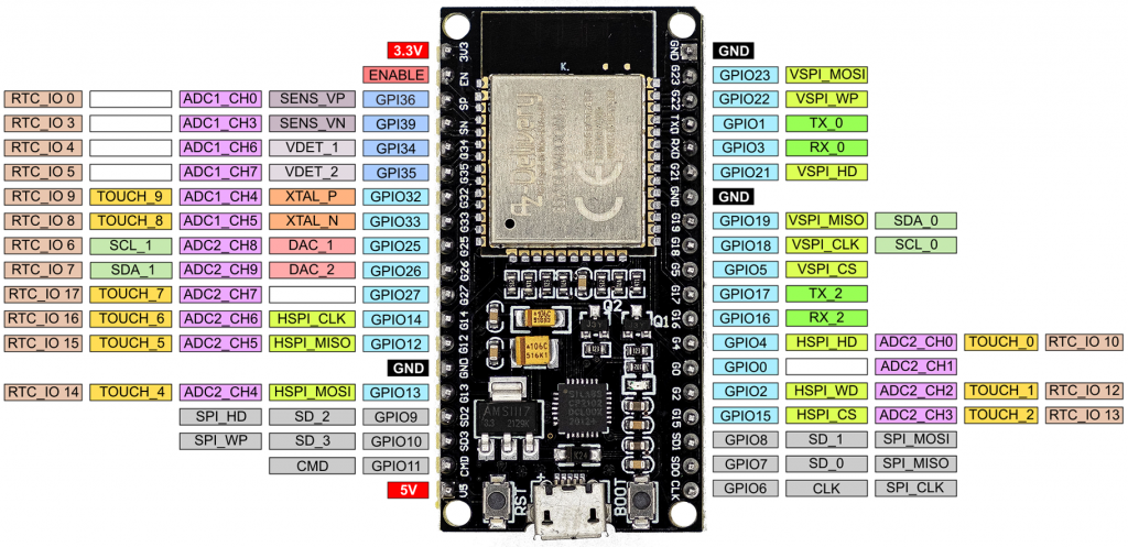
The only difference to the pin assignment in the Arduino implementation is the position of the I2C pins.
Short repetition: Switching and reading the GPIOs
Since I covered switching of GPIOs in detail in the last post, there is only a compact repetition here. A simple blink program on the ESP32 with MicroPython looks like this:
from machine import Pin
from time import sleep
led = Pin(18, Pin.OUT)
while True:
    led.value(not led.value())
    sleep(0.5)
The big difference to C++ is that the pins are defined as objects. Whether a pin acts as input or output is determined with Pin.OUT or Pin.IN. You can read the GPIO level with pinname.value(). You can switch the pin using pinname.value(0/1). In addition, you can connect internal pull-up or pull-down resistors if they are available at the respective pin. You would define a pin for reading a button state like this:
buttonPin = Pin(18, Pin.IN, Pin.PULL_DOWN) # button Pin = GPIO18
Read the ADCs of the ESP32 with MicroPython
First of all: As powerful as the ESP32 is, as bad are its A/D converters. They generate quite a bit of noise, and what’s worse, they are not linear. I have described this in detail here.
Now for the code:
from machine import ADC, Pin
from time import sleep

adc = ADC(Pin(32))

adc.atten(ADC.ATTN_11DB)    # ATTN_11DB, ATTN_6DB, ATTN_2_5DB, ATTN_0DB (default)
adc.width(ADC.WIDTH_12BIT)  # WIDTH_12BIT (default), WITDTH_11BIT, WIDTH_10BIT, WIDTH_9BIT

while True:
    val = adc.read()
    print("Raw ADC value:", val)
    sleep(1)
In order to use a pin as an A/D converter input, you first create an object. The default resolution is 12 bits. Alternatively, you can set with adc.width() 11, 10 or 9 bits. With adc.atten(ADC.ATTN_XDB) you set the attenuation and thus determine the input voltage range:
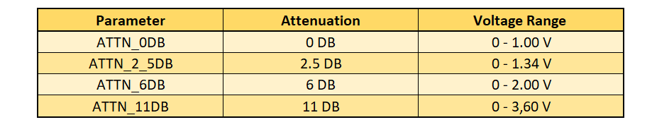
This data is from the MicroPython Quick Reference. In my own measurements, the A/D converter overflowed in the maximum range at about 3.15 volts.
Pulse width modulation
To produce pulse width modulation (PWM), you create a PWM object for a specific pin and pass the frequency and duty cycle. With the Arduino implementation of the ESP32 you can set the resolution (see here). If you program the ESP32 with MicroPython, only 10 bit resolution is available (0-1023). Here is an example:
from machine import Pin, PWM

pwm16 = PWM(Pin(16))     # create PWM object from GPIO 16
pwm16.freq(1000)         # 1 kHz
pwm16.duty(256)          # duty cycle = 256/1024 * 100 = 25%

# pwm16 = PWM(Pin(16), freq=1000, duty=256) # short Version
Other functions are:
pwm16.freq()             # get current frequency
pwm16.duty()             # get current duty cycle
pwm16.deinit()           # turn off PWM on the pin
The maximum PWM frequency is 40 MHz. However, due to the timer frequency of the ESP32 (80 MHz), you only get the full 10 bit resolution up to the following PWM frequency:
![\[ f_{\text{max, full res}}=\frac{80000000}{2^{10}}=78125\;\text{[Hz]} \]](https://wolles-elektronikkiste.de/wp-content/ql-cache/quicklatex.com-fd0abfe2f4cc6b377d2aec37832c6cf6_l3.png "Rendered by QuickLaTeX.com")
For larger frequencies, you can calculate the actual resolution as follows:
![\[ \text{res} = \frac{80000000}{f} \]](https://wolles-elektronikkiste.de/wp-content/ql-cache/quicklatex.com-463e7e41ce62932c68909f324b85b306_l3.png "Rendered by QuickLaTeX.com")
For example, if you choose 20 MHz as frequency, you only have a resolution of 4, i.e. you can set the duty cycles 0, 25, 50 and 75% by passing values in the ranges 0-255, 256-511, 512-767 or 768-1023 to pwm.duty().
Analog Pins
You can pick off a real analog signal between 0 and 3.3 V at pins 25 and 26. The resolution is 8 bits. Here’s how it works:
from machine import Pin, DAC
dac = DAC(Pin(25))
dac.write(128)       # voltage = 3.3 * 128/256
The drawback: the output voltage is linear to the value passed to dac.write(), but the slope of the straight line is not quite right. In my measurements, the range was 0.086 to 3.18 volts instead of 0 to 3.3 volts (see here).
Time functions
The equivalents to delay() and delayMicroseconds() when using ESP32 with MicroPython are sleep_ms() or sleep_us(). In addition, you can use sleep() which takes seconds as parameter.
millis() and micros() are called ticks_ms() and ticks_us() in MicroPython. With ticks_diff() you can determine time spans. Here is a small example:
import time

start_ms = time.ticks_ms()
start_us = time.ticks_us()
print("Millisecs: ", start_ms)
print("Microsecs: ", start_us)
time.sleep(3)
delta = time.ticks_diff(time.ticks_ms(), start_ms)
print("Delta =", delta)
The time module
With the time module, you can query the current time and the seconds since 01/01/2000, 00:00 o’clock. You can calculate the frequently used Unix time from this.
import time

now = time.localtime()           # query local time as tuple
print(now)
print(now[0])                    # print element 0
now_secs = time.time()           # secs since 01/01/2000, 00:00
now_unix = now_secs + 946681200  # unixtime: secs since 01/01/1970, 00:00
print(now_unix)
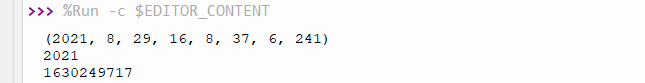
“localtime” is used as a tuple in the format:
(year, month, day of the month, hours, minutes, seconds, day of the week, day of the year)
The elements are integers. Here’s what the output looks like:
The RTC class
If you want to set the date and time of the ESP32, then you have to use the RTC class. The time tuple is structured a little differently:
(year, month, day of the month, day of the week, hours, minutes, seconds, microseconds).
On the day of the week, it should be noted that Monday is 0 and Sunday is 6. When setting the time, the day of the week is irrelevant. MicroPython will correct the day of the week if it is wrong.
from machine import RTC

rtc = RTC()
a = rtc.datetime()
print(a)
new_time= (2030, 12, 24, 0, 20, 35, 0, 0)
rtc.init(new_time)
a = rtc.datetime()
print(a)
We learn: December 24th, 2030 is a Tuesday:
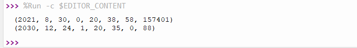
In addition, we learn: the time is set according to the system time of the computer when booting the ESP32.
Actually, the RTC class can do much more, e.g. alarm interrupts. However, this does not seem to have been implemented (yet) for the ESP32.
External interrupts
External (pin change) interrupts can be set up for each GPIO. This works similarly to the Arduino. The following program triggers an interrupt when a button attached to GPIO 23 is pressed. An LED on the GPIO 18 then lights up:
from machine import Pin
from time import sleep

led = Pin(18, Pin.OUT)
btn = Pin(23, Pin.IN, Pin.PULL_DOWN)

btn_pressed = False

def btn_handler(btn):
    global btn_pressed
    btn_pressed = True

btn.irq(trigger=Pin.IRQ_RISING, handler=btn_handler)

while True:
    if btn_pressed:
        led.value(1)
        sleep(1)
        led.value(0)
        btn_pressed = False
A few explanations:
- With
btn.irq()the pin “btn” gets an interrupt function.trigger=Pin.IRQ_RISINGcauses the interrupt to be triggered by the rising edge.- In addition, there is – surprise! – also
IRQ_FALLING.
- In addition, there is – surprise! – also
handler=btn_handlerdefines the interrupt handler, i.e. the function that is called when the interrupt is triggered (without parentheses).
- You must pass the pin object to the interrupt handler.
- In the handler function, btn_pressed must be set as global, otherwise Python considers the variable to be local.
Programming the timers of the ESP32 with MicroPython
Timers trigger internal interrupts. The ESP32 has 4 hardware timers with the ID 0 to 3, and they are easy to program. No comparison to the timers of the ATmega328P! Here is an example program that flashes 2 LEDs in asynchronously:
from machine import Pin, Timer

led0 = Pin(18, Pin.OUT)
led1 = Pin(19, Pin.OUT)

def handler_0(tim0):
    led0.value(not led0.value())

def handler_1(tim1):
    led1.value(not led1.value())

tim0 = Timer(0)
tim0.init(period=973, mode=Timer.PERIODIC, callback=handler_0)

tim1 = Timer(1)
tim1.init(period=359, mode=Timer.PERIODIC, callback=handler_1)
I think the code is almost self-explanatory:
- Timer is a class of the machine module.
- First you create a timer object and pass the timer ID (0 to 3).
init()expects three arguments:periodis the timespan in milliseconds until the timer interrupt is triggered.modeis eitherPERIODICorONE_SHOT.callbackdefines the function (interrupt handler) that will be called when the timer interrupt is triggered.
- As with external interrupts, you must pass the causing object to the handlers (tim0 and tim1 in this case).
Isn’t that wonderfully easy?
As an alternative to periods, you can also pass the frequency in Hertz, e.g.: freq = 20000.
Watchdog timer
The watchdog timer of the ESP32 is not particularly convenient, but easy to program. You create a WDT object and pass the timeout in milliseconds. Once started, it can no longer be stopped. It’s a bit unusual that you can only prevent the reset by a wdt.feed(). Other MCUs extend the timeout with any statement.
Here is an example:
from machine import WDT
from time import sleep

wdt = WDT(timeout=5000)

print("Hi, I have just booted")

while True:
    sleep(1)
    print("Still there...")
    #wdt.feed()
You will see that the ESP32 resets after 5 seconds. If you uncomment wdt.feed(), that doesn’t happen. By the way, the minimum timeout is 1 second.
I2C
The ESP32 has two I2C interfaces. I had explained this in detail here. In MicroPython, the interfaces are distinguished by their index (0 or 1). Interface 0 is assigned to GPIOs 18 (SCL) and 19 (SDA). Interface 1 is assigned to GPIOs 25 (SCL) and 26 (SDA). You can change the assignment and optionally specify the frequency. You do this when you create your I2C object.
from machine import I2C, Pin # I2C is a class in machine

i2c = I2C(0)   # simplest definition, SDA=GPIO19, SCL=GPIO18
i2c = I2C(1)   # SDA=GPIO26, SCL=GPIO25
i2c = I2C(0, scl=Pin(16), sda=Pin(17))  # new pin assignment
i2c = I2C(1, scl=Pin(12), sda=Pin(14), freq=400000) # new frequency and pin assignment
Scanning for I2C addresses is easy with scan(). The function returns a list of I2C addresses in decimal numbers:
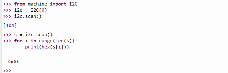
You write into registers via I2C with the function writeto_mem() and read them with readfrom_mem() or readfrom_mem_into(). You need to pass the I2C address and the register number to these functions. The data you write or query must be of type bytearray, even if it is only one byte. Here’s how the functions are used:
# writing to registers:
data = bytearray([128, 255]) # just an example
i2c.writeto_mem(I2C_ADDR, REG_ADDR, data)

# reading from registers:
data = i2c.readfrom_mem(I2C_ADDR, REG_ADDR, 2) # read two bytes
# or, alternatively:
data = bytearray(2)
i2c.readfrom_mem_into(I2C_ADDR, REG_ADDR, data)
You often need to read 16-bit values from two 8-bit registers and then combine the individual values to form an integer. This can be done as in C++ with shift operators (MSB<<8 | LSB). int.from_bytes(data, order) is less cryptic. Data is a bytearray that contains the bytes to be assembled, order is either “big” or “little”. “big” means that the MSB (Most Significant Byte) is first, with “little” it is at the end.
Then there is a small problem: how can MicroPython know whether the read data is signed or unsigned? With C++ you can specify that. The answer is: not at all, but you can easily solve this problem. For example, if you read a 16-bit signed integer((-215) to (+215-1), then the biggest positive value is 32767. Larger values are misinterpreted and actually negative. Because of the two’s complement representation, you just need to subtract 65536 (i.e.216). This applies at least to the current implementation of MicroPython on the ESP32. There are also Python versions in which you can pass int.from_bytes() to signed=true.
I2C example: Reading the MPU6050 on ESP32 with MicroPython
The following program provides the acceleration values, temperature and gyroscope data of an MPU6050. The example shows how compact MicroPython code can be.
from machine import I2C
from time import sleep

MPU_ADDR = 0x68
i2c = I2C(0)
i2c.writeto_mem(MPU_ADDR, 0x6B, bytearray([0])) # "wake-up call"

def byteToInt(bytePair):
    intVal = int.from_bytes(bytePair, 'big') # "big" = MSB at beginning
    if intVal > 32767:                       # intVal is negative => 2^15
        intVal -= 65536
    return intVal


while True:
    regVal = i2c.readfrom_mem(MPU_ADDR, 0x3B, 14)  # Read 14 bytes
    print("AccX =", byteToInt(bytearray([regVal[0],regVal[1]])))
    print("AccY =", byteToInt(bytearray([regVal[2],regVal[3]])))
    print("AccZ =", byteToInt(bytearray([regVal[4],regVal[5]])))
    print("Temp =", (byteToInt(bytearray([regVal[6],regVal[7]])))/340.00+36.53)
    print("GyrX =", byteToInt(bytearray([regVal[8],regVal[9]])))
    print("GyrY =", byteToInt(bytearray([regVal[10],regVal[11]])))
    print("GyrZ =", byteToInt(bytearray([regVal[12],regVal[13]])))
    print("***************")
    sleep(2)
First, the MPU6050 is woken up by writing a zero to its register 0x6B (“Powermanagement 1”). The measured values are available in fourteen registers, starting from 0x3B, and they are read in one go. 2 bytes each of the bytearray regVal form one of the 7 measured values.
Most of the time, however, you will probably not want to deal with registers and therefore choose external modules. I come to that now.
Adding external (I2C) modules
First of all, there is a certain confusion of names here. You will find the terms module, library and package. In first approximation, the terms mean the same thing.
For many components such as sensors, displays, ADCs, etc., hard-working people have written modules. To use them, you have to install them in most cases.
If you work with Thonny, then it is best to use the package manager. Go to Tools → Manage Packages. Enter the name and search for PyPI. Select the package, install it, and you can immediately use it. This is similar to the library management in the Arduino IDE. Only the handling of example programs is less well solved. To get them, you have to go to the platforms where the packages are made available.
However, there may also be modules that you cannot find via the package management. Maybe you programmed them yourself. In this case, take the file to be included, right-click on it in Thonny and select “Upload to \”. Then you can use the classes and functions.
uPyCraft does not have a package management. There, you open the file to be included and select “Download”.
SPI
The ESP32 has four SPI interfaces, of which you can use two. They are called HSPI and VSPI and they are addressed via their IDs 1 and 2 respectively. By default, the following pins are assigned to the interfaces:
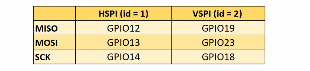
You can easily change the pin assignment. The creation of SPI objects is similar to I2C. You can pass different parameters:
from machine import Pin, SPI

hspi = SPI(1) # use default Pins
hspi = SPI(1, 20000000)
hspi = SPI(1, baudrate=20000000, sck=Pin(14), mosi=Pin(13), miso=Pin(12))
vspi = SPI(2, baudrate=40000000, polarity=0, phase=0, bits=8, firstbit=0, sck=Pin(15), mosi=Pin(16), miso=Pin(17))
When using the standard GPIOs, the baud rate can be up to 80 MHz. If you choose other GPIOs, the baud rate is limited to 40 MHz.
Reading and writing to registers is also similar. The data is passed and received as bytearrays. Here is an example of how to use the most important functions:
spi.read(5)             # read 5 bytes
spi.read(5, 0xFF)       # read 5 bytes and write 0xFF

buf = bytearray(20)
spi.readinto(buf)       # read into the given buffer
spi.readinto(buf, 0xFF) # read into the buffer and write 0xFF

spi.write(buf)          # write buffer
spi.write_readinto(buf_1, buf_2) # write buf_1 and read into the buf_2
UART (Serial)
The ESP32 has the three UART interfaces UART0, UART1 and UART2. By default, these are assigned to the following GPIOs:

When choosing the pins, you have to be a bit careful. You should not use the standard GPIOS for UART0 and UART1 (see also here).
Things repeat. Again, you first create a UART object, where you can pass several parameters. At least you have to pass the UART ID. Here is an example:
from machine import UART

uart1 = UART(1, baudrate=115200, tx=18, rx=19)
And here are a few – I think self-explanatory – statements:
uart1.init(9600, bits=8, parity=None, stop=1) # standard settings
uart1.read(7)        # read 7 characters, returns a bytes object, not bytearray
uart1.read()         # read all available characters
uart1.readline()     # read a line
uart1.readinto(buf)  # read and store into buf
uart1.write('xyz')   # write the 3 characters
uart1.any()          # returns number of bytes available
Deep and Light Sleep
To save power, the ESP32 has a light sleep and a deep sleep function. After a light sleep, the program picks up where it left off. A deep sleep causes a reset. The setting is very easy on the ESP32 with MicroPython. You can try the following program:
import machine, time

if machine.reset_cause() == machine.DEEPSLEEP_RESET:
    print("woke up from a deep sleep")

while True:
    #machine.deepsleep(3000)
    machine.lightsleep(3000)
    print("woke up from a light sleep")
    time.sleep(0.1)
Without the small time.sleep() delay, print() did not work properly for me. Apparently, the ESP32 goes to sleep before the print() instruction is completely processed.
Touch Pins
The touch pins register capacities. Since the human body also has a certain capacity, the touch pins serve as touch sensors. Here’s how it works:
from machine import TouchPad, Pin
from time import sleep

t = TouchPad(Pin(32))

while True:
    t_val=t.read()
    print("Touch value:", t_val)
    sleep(0.5)
The initial values (ESP32 used on a breadboard) were around 800 for me. When I touched the touch pin via a jumper cable, the values dropped below 100.
A touch event can wake the ESP32 from both light and deep sleep. Here’s how it works:
import machine
from machine import TouchPad, Pin
import esp32
from time import sleep

t = TouchPad(Pin(32))
t.config(300)               # configure the threshold at which the pin is considered touched
esp32.wake_on_touch(True)

while True:
    machine.lightsleep()    # put the MCU to sleep until a touchpad is touched
    print("Woke up from light sleep")
    sleep(1)
    print("Falling asleep again")
    sleep(0.1)              # you can try without this
Hall Sensor
The ESP32 has a Hall sensor that detects magnetic fields. It is easy to read:
import esp32, time

while True:
    m = esp32.hall_sensor()
    print(m)
    time.sleep(2)
Wi-Fi
One of the great advantages of the ESP32 is the integrated WLAN. However, the topic is quite extensive and would go beyond the scope of this post. Maybe I’ll cover it in a later article.
If you want to deal with the topic in more detail, then I recommend this tutorial as a starting point. There it is shown how to set up a web server with the ESP32 and how to then switch an LED via browser. The instructions worked wonderfully for me right away.
Bluetooth
With Bluetooth, a distinction is made – among many other things – between Bluetooth Classic and BLE (Bluetooth Low Energy). You may know the classic version from the HC-05 and HC-06 modules or from my article about programming the ESP32 with Arduino code. The advantage is the simple programming.
The BLE variant, as its name suggests, is more energy-saving. More about the differences between Classic and BLE can be found here. Unfortunately, Classic Bluetooth is not (yet?) implemented in MicroPython. On the other hand, BLE is a somewhat more complex topic that would go beyond the scope here. And honestly, I have some learning to do on this topic as well.
Danke für deine zahlreichen TOP-Lernartikel!
Ich möchte gerne an die Energiewerte meiner Tapo-Steckdose rankommen.
Hier habe ich erstmals einen Weg gesehen: https://pypi.org/project/tapo/
Kann man sowas auch auf einem einem ESP32 spielen? Wenn ja, gibt es weitere Hilfestellungen für Anfänger um genau das umzusetzen ?
Bisher arbeite ich nur mit Tasmota, ESP Easy und ein wenig mit der Arduino IDE.
Danke für die Antwort!