About the post
A lot has already been published about the ESP8266 ESP-01 module. So why another post about this topic? Until I was able to do everything I had planned to do with my ESP-01 module, it took a lot of time, despite the wealth of information available, because the required details were spread over many sources. Therefore, here is the attempt to introduce the basic functions step-by-step and not too long but comprehensible. I focus on programming with the Arduino IDE. Im Einzelnen behandele ich die folgenden Themen:
- Integration of the ESP8266 product family into the Arduino IDE
- Circuit for programming with an Arduino
- Circuit for programming with a USB-to-TTL adapter
- Control of the GPIOs via WLAN
- Displaying measured values on a website and updating them regularly
- Updating/restoring the firmware
- Control of the ESP8266 ESP-01 module via AT commands (set up a server / switching GPIOs)
- LUA programming (only as reference)
Basics
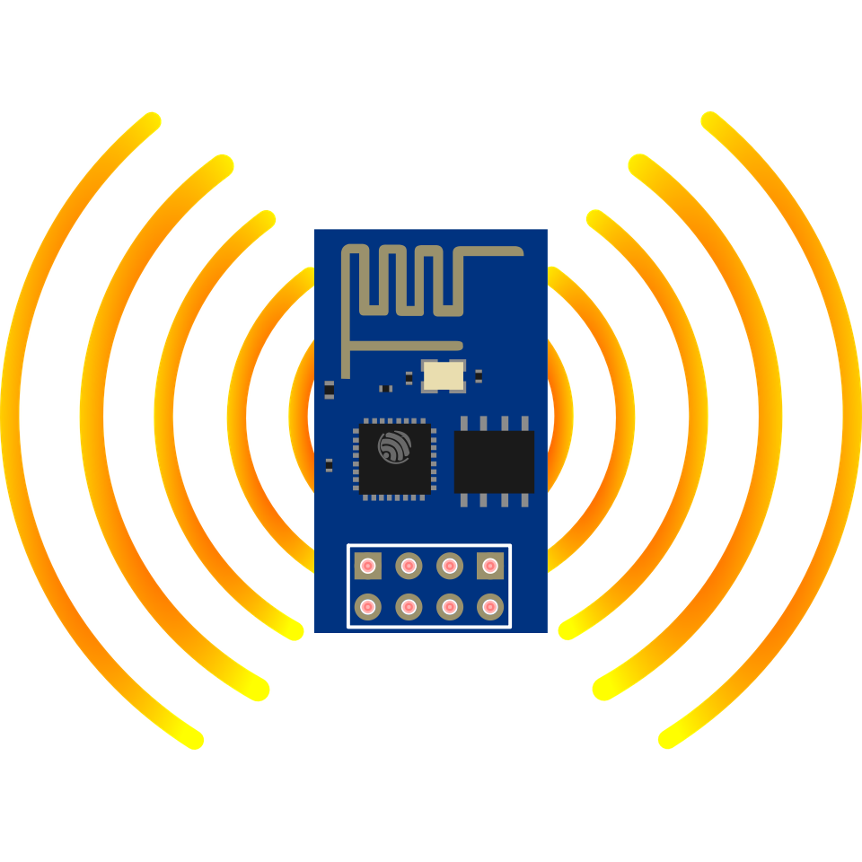
An ESP8266 ESP-01 module or, in short, ESP-01 module is based on the ESP8266 chip from Espressif. This chip is used on various modules, whereby the ESP-01 module is the simplest variant. It is basically a fairly powerful microcontroller with integrated Wi-Fi.
The original firmware allows programming via the somewhat cryptic “AT commands”, which you may know from Bluetooth modules such as the HC-05 and HC-06. I have described these components here. Smart people have made it possible to program the ESP8266 modules with the Arduino platform, which is the main topic of this article. Later, however, I will also briefly mention the AT commands.
Note: Once you have uploaded an Arduino Sketch, the firmware is overwritten and the module no longer understands AT commands. Then you have to flash it again with the original firmware. This is not a big deal, but it requires a few steps. More on that below.
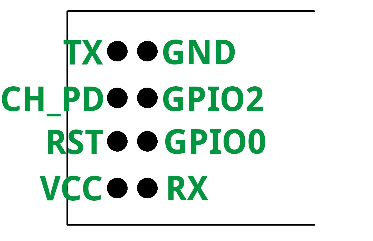
Pinout of the module

The ESP-01 module has 8 pins arranged in such a way that you cannot connect it directly with a breadboard. Because of this and because it is easy to mix up the pins due to the missing label, I recommend buying a small adapter (see photo). You get the module including the adapter e.g. at Amazon for 5 – 10 Euro.
The module is powered via VCC/GND. The voltage should be between 2.5 and 3.6 volts. For serial communication the module uses TX and RX. If you program via an Arduino, strictly speaking, a voltage divider or logic level converter must be set in front of RX, so that the 3.6 volts are not exceeded. The CH-PD is the enable-pin and is connected to the power supply. The RST pin triggers a reset if it is set for short time to “LOW”. GPIO0 and GPIO2 (General Purpose Input Output) are the two programmable I/O pins. GPIO0 is also required to set the ESP8266 ESP-01 module into programming mode. For this purpose, this pin is connected to GND when the power supply is switched on or during a reset. After that, the connection to GND can be disconnected. The module remains in programming mode until a sketch is uploaded.
You can use TX as GPIO1 and RX as GPIO3 and thus you have four I/O Pins. Nevertheless, the ESP8266 ESP-01 module is of course a little limited in its possibilities due to the small number of GPIOs. Those who need more can rely on the larger representatives of the ESP8266 module family, in particular the ESP-12. In a further post I will also show how to make port expansion with GPIO0 and GPIO2.
ESP-01 vs. ESP-01S

In addition to the ESP-01, there is also the newer ESP-01S variant. It is still based on the same ESP8266EX microcontroller, but the board has a few advantages:
- 4 MB vs. 1 MB Flash-Speicher
- 12 kΩ pull-up resistors on RST, GPIO0 and CH_PD
- On-Board LED on GPIO2
The pull-up resistors can simplify programming and make the booting process more reliable.
Preparing the Arduino IDE
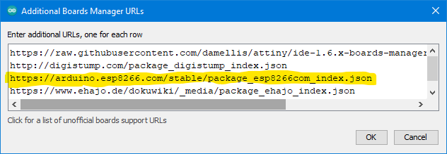
It takes less than two minutes to extend the Arduino IDE to include the ESP8266 modules. In the first step, you have to enter the appropriate board manager URL. To do this, you need to go to File – > Preferences and click on the icon marked in red:

Then enter the address: “http://arduino.esp8266.com/stable/package_esp8266com_index.json” as a separate line and confirm with “OK”:
The next step is to go to Boards Manager, search for “esp8266” and install the package:


Finally, you have to restart the Arduino IDE and that’s it.
Upload sketches
Uploading via Arduino-Boards
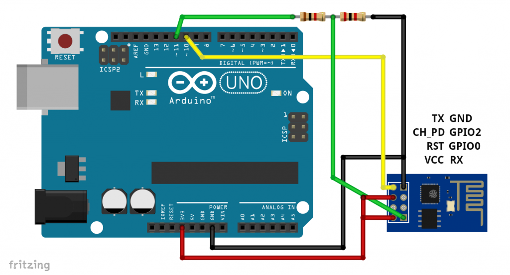
You can program the ESP-01(S) with an Arduino board (e.g.: UNO/ Nano Classic). Be aware: it is much easier using a programmer which I show later.
- TX is attached to TX and RX to RX; Vmax of the RX pin of the ESP01 is 3.6V.
- therefore use a voltage divider (if you don’t have the resistors shown, you can also use two 10 kΩ resistors).
- Attach the reset pin of the Arduino to GND or upload the bare minimum sketch to the Arduino.
- VCC (ESP-01): The ESP-01 consumes more current at peak times than the 3.3 V pin of the Arduino can supply. An external 3.0 – 3.6 V power source is recommended.
- GND to GND
- CH_PD to 3.3V (obsolete for the ESP-01S).
- GPIO0 to GND (to enter programming mode), indicated here by the switch. In normal mode, connect GPIO0 via a pullup resistor to HIGH (obsolete for ESP-01S).
- Connect RST (ESP-01) with a pull-up resistor to HIGH (obsolete for ESP-01S). For a reset, connect RST to GND, e.g. via a pushbutton.

Choose “Generic ESP8266 Module” in the Arduino IDE as board. Apart from the port, you leave the other settings as they are.

A simple blink sketch is a good test:
int LEDPin = 2; // GPIO2

void setup() {
  pinMode(LEDPin, OUTPUT);
}

void loop() {
  digitalWrite(LEDPin, LOW);
  delay(500);
  digitalWrite(LEDPin, HIGH);
  delay(500);
}
If you then connect an LED to GPIO2, it should work. If not, perform another reset or briefly disconnect the power supply.
Confused? Here is the upload process in short (thanks to Christian!):
- Set up the circuit as described (GPIO0 connected to GND).
- Connect the circuit to power.
- Briefly press the pushbutton.
- Disconnect GPIO0 from GND.
- Upload your sketch.
- Briefly press the pushbutton.
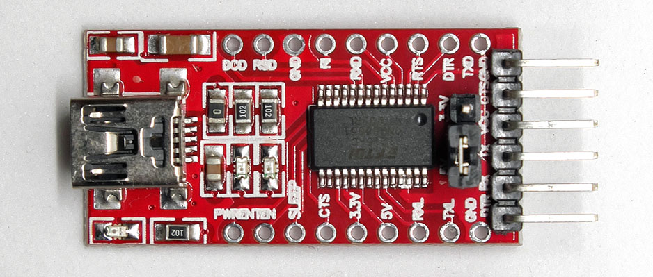
Upload via USB-to-TTL adapter
If you take a USB-to-TTL adapter instead of an Arduino, it is best to choose a model where you can set 3.3 V. Here is an example:
It is important that you connect now RX to TX and TX to RX. A voltage divider for RX is omitted if you can set your adapter to 3.3 volts.

Again, the pull-up resistors on GPIO0 and Reset and the connection of CH_PD to HIGH are obsolete if you use an ESP-01S.
Programmer
As previously mentioned, flashing the ESP01 modules using a programmer is much easier. All you have to do is attaching the ESP-01, plug the programmer into the USB socket, set the port in the Arduino IDE and upload your sketches. Such programmers are available for 10 euros or less. Here are two examples:


The lower model has an additional pin header so that you do not have to reconnect the ESP-01 from the programmer to your project circuit.
In addition to the programmers, there are also ESP-01 adapters. These can not automatically pull the GPIO0 to GND or perform a reset. The parts are OK for normal operation (or for programming via AT commands), but are not recommendable for flashing sketches.
Here are two examples:

Control of the GPIOs via WiFi
To “warm up”: send a message to the browser
Controlling the ESP8266 by WiFi is quite an extensive topic, which I have covered in a separate article (link). There you can delve deeper into this matter. Perhaps the following examples will whet your appetite.
You only have to adjust the following sketch slightly. At the beginning of the sketch, a server is defined: ESP8266WebServer Server(80);. 80 is the default port, so you can access the website without specifying the port in the browser. In this, as well as the following sketches, you only find the following in the main loop: server.handleClient(); What is actually interesting is defined by server.on("/",handleRoot);
#include "ESP8266WiFi.h"
#include "ESP8266WebServer.h"
const char* ssid = "Eure SSID";
const char* pass = "Euer WLan Passwort";
IPAddress ip(192,168,178,xxx); // 192.168.178.xxx = freie IP Adresse, ggf. müsst ihr auch die anderen Zahlen anpassen; schaut am besten in euren Router
IPAddress gateway(192,168,178,1);
IPAddress subnet(255,255,255,0);
ESP8266WebServer server(80);
void handleRoot() {
String message="<h1>Minimalprogramm ESP8266</h1>";
message += "Hallo ... !!!! Dieses ist ein netter Gruß vom ESP8266 Server";
server.send(200, "text/html", message);
}
void setup(){
WiFi.begin(ssid, pass);
WiFi.config(ip, gateway, subnet);
server.on("/",handleRoot);
server.begin();
}
void loop(){
server.handleClient();
}
After you have uploaded the sketch, you chose your favorite browser and navigate to the IP address, in this case “192.168.178.xxx”. I had no problems with Firefox and Chrome, Edge was sometimes a bit tricky. So if you have problems, you might change your browser and don’t immediately doubt your code.
Switching via Wi-Fi
In this example, an LED attached to GPIO0 is switched via Wi-Fi and browser. The sketch is similar to the one above. Here, however, two subpages have been added, which are called by links (” < a href=…… > ” and that triggers the execution of the corresponding functions (ledan(), ledaus() ). Some German lessons: an = on, aus = off!
If you uncomment the commented lines, you can track the connection on the serial monitor. For me, however, this has led to difficulties in accessing the web pages. So I would only do that for testing purposes.
#include "ESP8266WiFi.h"
#include "ESP8266WebServer.h"
#define LEDPIN 0
const char* ssid = "Eure SSID";
const char* pass = "Euer WLAN Passwort";
IPAddress ip(192,168,178,xxx); // Individuell anzupassen
IPAddress gateway(192,168,178,1);
IPAddress subnet(255,255,255,0);
ESP8266WebServer server(80);
String led1= "<a href=\"/led_an\">LED An</a>";
String led0= "<a href=\"/led_aus\">LED Aus</a>";
void handleRoot() {
String message="<h1>Testprogramm - Minimalprogramm ESP8266</h1>";
message += "Hallo ..., das ist ein Gruß vom ESP8266 Server</BR></BR>";
message += led1;
server.send(200, "text/html", message);
}
void ledan(){
digitalWrite(LEDPIN, HIGH);
server.send(200, "text/html", led0);
}
void ledaus(){
digitalWrite(LEDPIN, LOW);
server.send(200, "text/html", led1);
}
void setup(){
pinMode(LEDPIN, OUTPUT);
digitalWrite(LEDPIN, LOW);
// Serial.begin(9600);
// Serial.println("Testprogramm - Minimalprogramm ESP8266");
// Serial.print("Verbinde mich mit Netz: ");
// Serial.println(ssid);
WiFi.begin(ssid, pass);
WiFi.config(ip, gateway, subnet);
// while(WiFi.status() != WL_CONNECTED){
// delay(500); Serial.print(".");
// }
// Serial.println("");
// Serial.println("WiFi Verbindung aufgebaut");
// Serial.print("Eigene IP des ESP-Modul: ");
// Serial.println(WiFi.localIP());
server.on("/",handleRoot);
server.on("/led_an", ledan);
server.on("/led_aus", ledaus);
server.begin();
// Serial.println("HTTP Server wurde gestartet!");
}
void loop(){
server.handleClient();
}
Switching two LEDs
The switching of two LEDs can also be done with this methodology:
#include "ESP8266WiFi.h"
#include "ESP8266WebServer.h"
int led[2] = {0,2};
bool led_status[2] = {false};
String message = "";
String title = "<h1>Testprogramm - Minimalprogramm ESP8266</h1>"
"Hallo Wolle, das ist ein Gruß vom ESP8266 Server</BR></BR>";
const char* ssid = "Eure SSID";
const char* pass = "Euer WLAN Passwort";
IPAddress ip(192,168,178,xxx);
IPAddress gateway(192,168,178,1);
IPAddress subnet(255,255,255,0);
ESP8266WebServer server(80);
String led0_1= "<a href=\"/led0_an\">LED0 An</a>";
String led0_0= "<a href=\"/led0_aus\">LED0 Aus</a>";
String led1_1= "</BR><a href=\"/led1_an\">LED1 An</a>";
String led1_0= "</BR><a href=\"/led1_aus\">LED1 Aus</a>";
void setup(){
pinMode(led[0], OUTPUT);
digitalWrite(led[0], LOW);
pinMode(led[1], OUTPUT);
digitalWrite(led[1], LOW);
WiFi.begin(ssid, pass);
WiFi.config(ip, gateway, subnet);
server.on("/",handleRoot);
server.on("/led0_an", led0an);
server.on("/led0_aus", led0aus);
server.on("/led1_an", led1an);
server.on("/led1_aus", led1aus);
server.begin();
}
void loop(){
server.handleClient();
}
void handleRoot() {
message = "";
message += title;
message += led0_1;
message += led1_1;
server.send(200, "text/html", message);
}
void led0an(){
led_status[0] = true;
switchLED(0,1);
}
void led0aus(){
led_status[0] = false;
switchLED(0,0);
}
void led1an(){
led_status[1] = true;
switchLED(1,1);
}
void led1aus(){
led_status[1] = false;
switchLED(1,0);
}
void switchLED(int num, bool state){
message = "";
message += title;
digitalWrite(led[num], state);
(led_status[0]==true)?(message += led0_0):(message += led0_1);
(led_status[1]==true)?(message += led1_0):(message += led1_1);
server.send(200, "text/html", message);
}
Displaying measured values and updating them automatically
With two GPIOs, of course, you have limited options. This is probably why almost everyone who writes an introduction about the ESP8266 ESP-01 module uses temperature measurement via a DS18B20 sensor as an application example. Because this works with the One Wire technology. Where I2C and SPI need two or three communication lines, One Wire – as the name suggests – can do with a single one.
Since this is a post about the ESP-01 module and not about the DS18B20 sensor, I will not go into the details and refer to the many tutorials available on the net. But at least few words about the sensor: the DS18B20 is available both as a TO-92 (“three-legged”) and as a waterproof version. I use the latter:
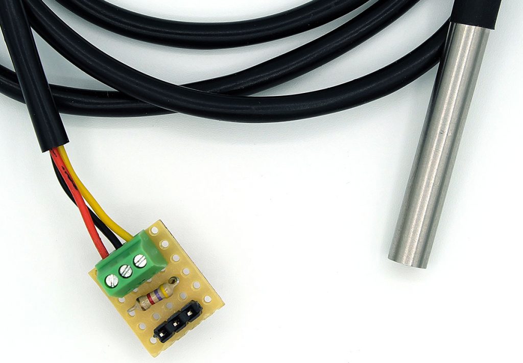
The part is supplied with the bare connection cables. I made a breadboard adapter with a piece of PCB prtotyping board. Black (GND) is connected to GND, red (VCC) to 3.3 volts (5 volts also goes) and yellow (DATA) to GPIO0 or GPIO2, depending on the programming. It should also be noted that the data line requires a pullup resistor of 4.7 kOhm.
The sketch
#include <OneWire.h>
#include "ESP8266WiFi.h"
#include "ESP8266WebServer.h"
int DS18B20_Pin = 2;
OneWire ds(DS18B20_Pin);
const char* ssid = "Eure SSID";
const char* pass = "Euer WLAN Passwort";
IPAddress ip(192,168,178,xxx); //Anzupassen
IPAddress gateway(192,168,178,1);
IPAddress subnet(255,255,255,0);
ESP8266WebServer server(80);
void setup() {
WiFi.begin(ssid, pass);
WiFi.config(ip, gateway, subnet);
server.on("/",handleRoot);
server.begin();
}
void loop() {
server.handleClient();
}
void handleRoot() {
String message= "<head><meta http-equiv=\"refresh\" content=\"10\"></head>"
"<h1>Temperaturprogramm ESP8266</h1><BR><BR>"
"Die Temperatur beträgt: ";
static String tString = "";
static unsigned long lastMeasure = 0;
if((millis()-lastMeasure) > 5000){
float temperature = getTemp();
tString = String(temperature);
lastMeasure = millis();
}
message += tString;
server.send(200, "text/html", message);
}
float getTemp(){
byte data[12];
byte addr[8];
if ( !ds.search(addr)) {
//no more sensors on chain, reset search
ds.reset_search();
return -1000;
}
ds.reset();
ds.select(addr);
ds.write(0x44,1); // start conversion
ds.reset();
ds.select(addr);
ds.write(0xBE); // read Scratchpad
for (int i = 0; i < 9; i++) { // we need 9 bytes
data[i] = ds.read();
}
ds.reset_search();
byte MSB = data[1];
byte LSB = data[0];
float tempRead = ((MSB << 8) | LSB); //using two's compliment
float TemperatureSum = tempRead / 16;
return TemperatureSum;
}
I do not go into the DS18B20 related part in more detail. At this point, simply take as a given fact that the getTemp() function returns the temperature as a float. If you compare the code with other sketches for the DS18B20, it might seem a little more complicated here. You can simplify it theoretically by including the “DallasTemperature” library, but then I had problems with the web page connection – for whatever reason.
The rest should be relatively clear. The temperature is measured every five seconds. To update the website regularly, the HTML code <head><meta http-equiv=\"refresh\" content=\"10\"></head> was inserted. The “10” means that a refresh is performed every 10 seconds.
And another note: quotation marks need an additional backslash so that they are not interpreted as Arduino code.
Reinstalling the firmware
As mentioned above, uploading the Arduino sketches will overwrite the original firmware, so that control via AT commands is no longer possible. However, you can restore the AT software or choose a newer version. This is a little laborious, because you have to install a small tool. A good instruction can be found here. If you stick to it (exactly!), it works.
Control via AT commands
This will not be a detailed introduction to the AT commands. I would just like to use two examples to give an impression of how AT commands work. A list of AT commands can be found here.
Note: Not all AT commands work with every firmware version.
The setup
The circuit for transmitting the AT commands to the ESP8266 ESP-01 module is fundamentally different from the circuit for uploading sketches and firmware. RX is hooked up to TX (via SoftwareSerial), TX to RX. A voltage divider is applied between the Arduino TX and the RX of the ESP-01. GPIO0 is not connected to GND because you don’t go into programming mode. Of course, the transmission of the AT commands is also a kind of programming, but it’s not a whole program that is transferred. In addition, the reset pin remains unconnected.
To enable communication, a SoftwareSerial is set up. When uploading, you now have to choose the Arduino as the board.
#include <SoftwareSerial.h>
SoftwareSerial mySerial(10, 11);

void setup() {
  Serial.begin(9600);
  Serial.println("Los geht's");
  mySerial.begin(115200);
}

void loop() { // run over and over
  if (mySerial.available()) {
    Serial.write(mySerial.read());
  }
  if (Serial.available()) {
    mySerial.write(Serial.read());
  }
}
Setting up a server with AT commands
After the softwareSerial Sketch has been uploaded, you open the serial monitor, set the baud rate to 9600 and select the option “Both NL and CR”. Sending “AT” should be answered by the module with “OK”. If it doesn’t, you’ll have to check all settings and flash the module again with the firmware if necessary (see above).
If everything works, “AT+GMR” will provide the version of the firmware. To display a message in your browser, enter the following AT commands:
AT+CWMODE=1 –> Station Wi-Fi Mode
AT+CWJAP=“eure SSID“,“WiFi-Zugangspasswort“ — > connect to Wi-Fi; enter this including quotation marks
AT+CIFSR — > here you can see your IP address
AT+CIPMUX=1 — > connection mode (Multiple)
AT+CIPSERVER=1,80 –> 1: create server, 80: Port
At this point you can start your browser and enter the IP address. As you see, you don’t see anything yet.
AT+CIPSEND=0,5 — > channel and number of characters
A ” > ” appears. You enter “Hello” without quotation marks, then press enter
AT+CIPCLOSE=0 — > Only now a friendly “Hello” appears in the browser.
Controlling GPIOs with AT commands
First of all: controlling the GPIOs did not work with my ESP8266 ESP-01 modules until I updated the firmware according to the instructions above.
To switch GPIO2, enter:
AT+SYSIOSETCFG=2,0,0 — > 2: pin, 0: mode, 0: no pullup
AT+SYSGPIODIR=2,1 –> 2: pin, 1: output
AT+SYSGPIOWRITE=2,1 –> 2: pin, 1: HIGH
AT+SYSGPIOWRITE=2,0 –> 2: pin, 0: LOW
Programming with LUA
In addition to programming with Arduino and AT commands, there is a third variant, namely programming with the rather simple programming language LUA. To do this, you must first flash your module with the nodeMCU firmware. The procedure is described very well here. I’m not going into it.
Getting deeper
If you want to get even deeper, you can try the Manufacturer’s Getting Started Guide. A very good site that explains the basics well is this one. I also recommend browsing the various example sketches you will find after installing the ESP8266 board family in the Arduino IDE.
At a later stage, I will make a post about the big brother of the ESP-01, the ESP-12. I also have in mind to do introduce ways to expand the ESP-01 port. Stay tuned!
Tolle Beiträge, da steckt viel Arbeit drin. Ich würde mich freuen Mails bei neuen Beiträgen zu erhalten. Grüße / Elmar
Vielen Dank für’s feedback. Du kannst bei neuen Beiträgen informiert werden. Weiter unten oder ganz oben rechts unter Abo/Subscription kannst du dich eintragen – und auch jederzeit wieder abmelden. Aus Gründen des Datenschutzes erhältst du nach dem Eintragen noch eine E-Mail in der du gebeten wirst, den Wunsch noch einmal zu bestätigen. Diese mails landen häufig in Spam Ordnern, also da mal schauen, wenn nichts kommt.
Das ist übrigens die englische Version – du kannst auch auf Deutsch wechseln.
VG, Wolfgang