About this post
In this post, I would like to give an introduction to Blynk. Blynk is an IoT (Internet of Things) platform that allows you to easily and conveniently read sensors, switch devices, automate processes or remotely inform yourself about critical conditions. Once the basic principle is understood, most functions can be used intuitively and with little programming effort.
I had already introduced similar platforms like the Arduino IoT Cloud and Arduino SIM / Sigfox. IFTTT (If-This-Then-That) can also be used to control things in the IoT. All these IoT platforms have their specific advantages and disadvantages. What I particularly like about Blynk is the wide range of functions, the simple operation and the exemplary documentation. The free version is limited to two devices, 5 users and 30 widgets (functions). You can play around with two devices, but you can’t automate a whole house, for example. How you can implement more devices despite the limitation (but with certain restrictions), I explain at the end of the post.
I will cover the following topics:
- Blynk Quick Start
- Templates
- Quickstart Code
- Virtual Pins
- Adding templates and devices
- Adding widgets
- Automations and notifications
- “Bypass” device limitation
Smartphone vs PC
In this article, I will focus on operation from a PC. But Blynk is also available as an app for iOS (here) and for Android (here). If you can cope with the PC version, you can also use the app in no time. Setting up on the PC is easier for me personally than on the smartphone. Controlling things later, on the other hand, is more fun on the smartphone and may also make more sense.
The ratings of the apps are rather mediocre. The main reason seems to be that more devices used to be able to use the free version. Now, many are disappointed because of the limitations.
Blynk Quick Start
Let’s start right away. First, you only need a microcontroller board. The most useful is one with integrated WiFi, such as an ESP32, ESP8266 / Wemos, Arduino MKR1010 or Arduino Nano 33IoT. Navigate to the Blynk website, click on “Start free” and create an account. Languages available are English, German and Russian.
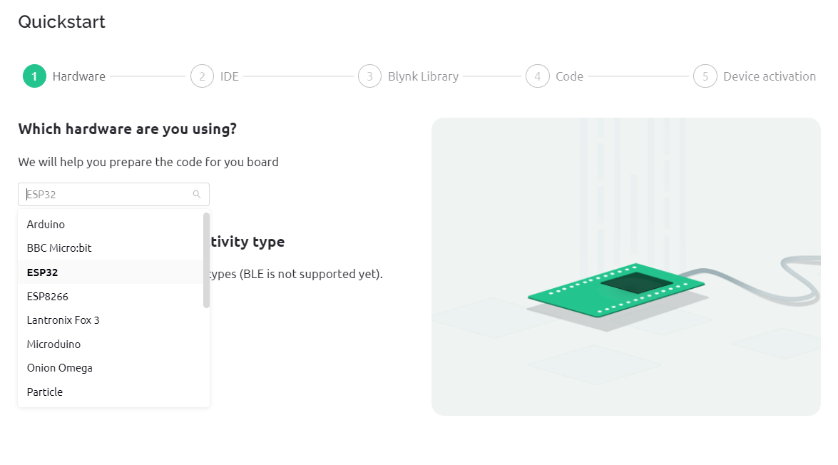
You can have your board online in five to ten minutes at the most using the “Quick Start”. Select the correct board and connection type:
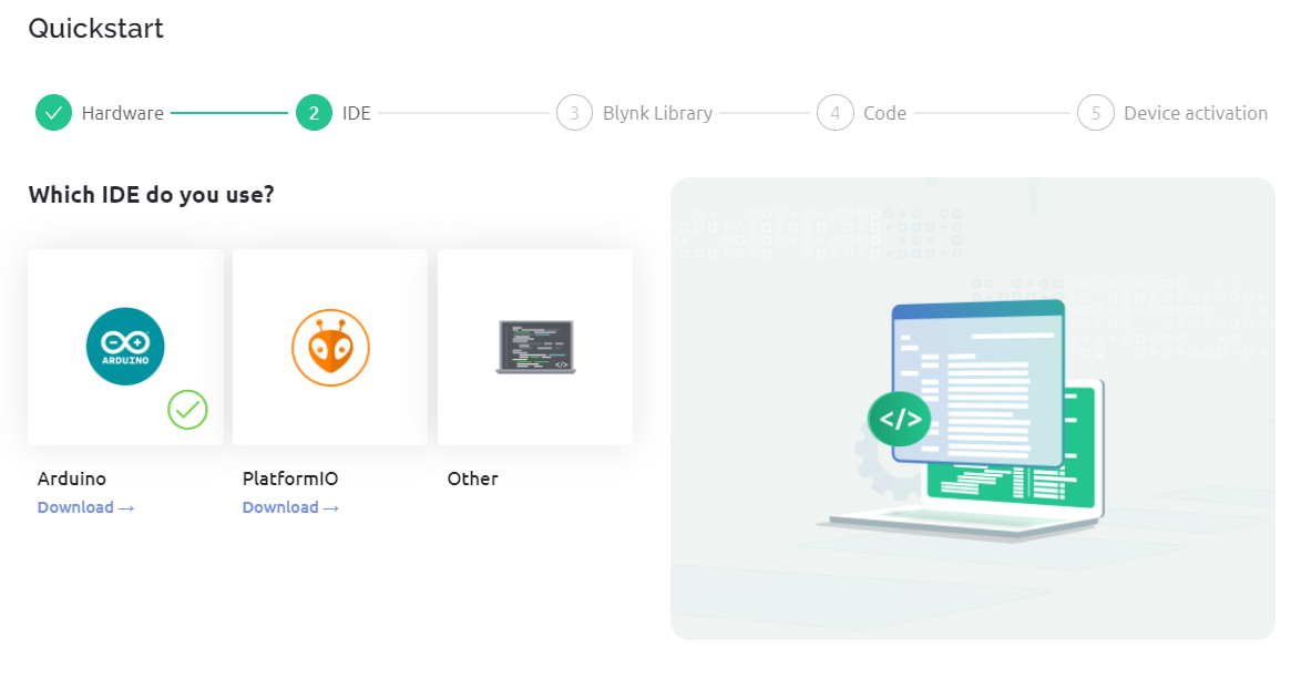
Now you choose your development environment (IDE):
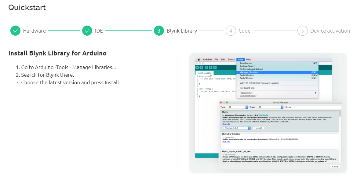
Install the Blynk library:
Enter your Wi-Fi credentials. These are transferred directly to the quick start sketch and are not stored on Blynk. If you don’t trust the system, you can also insert the access data manually later into the sketch. You can download the sketch or copy the code. Then upload the sketch to your board.

If everything worked out, your board is now online and you will be rewarded with a shower of confetti:
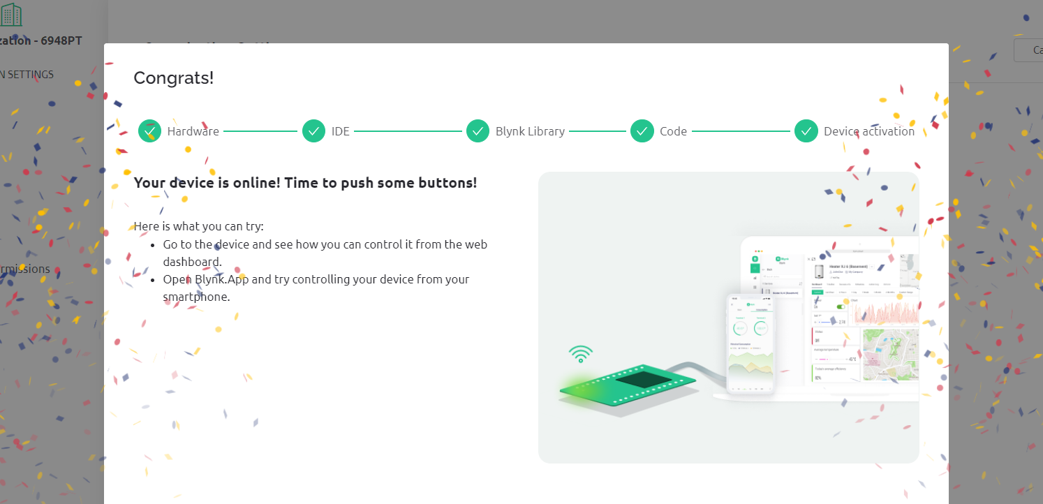
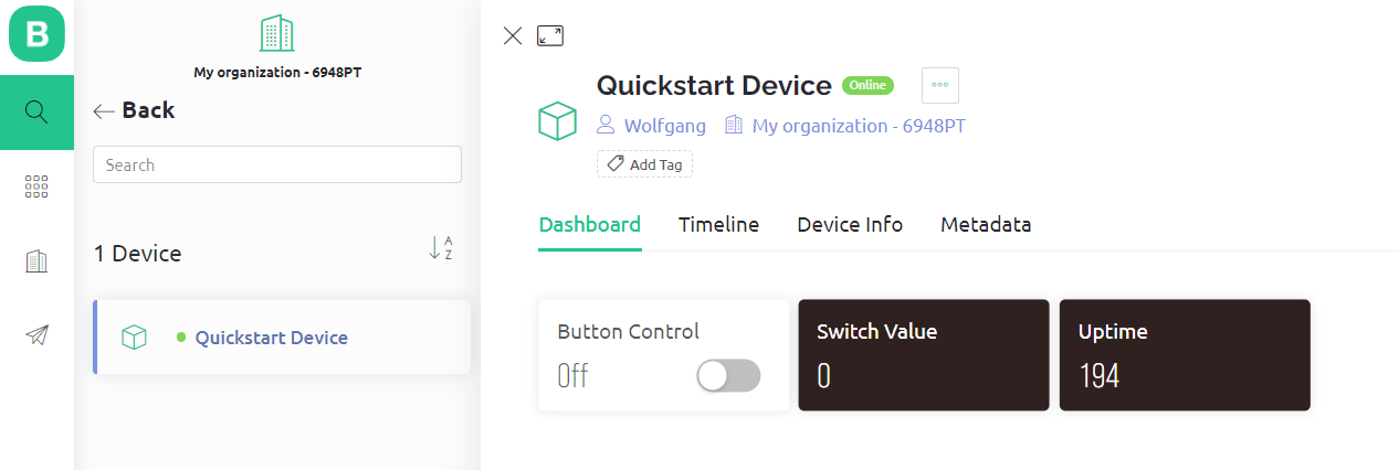
The window you’re in is the Blynk console. Use the magnifying glass icon to navigate to your board, which Blynk has created under the name “Quickstart Device”. There you will find the pre-installed widgets in the dashboard. The Dashboard is your control center from which you steer your microcontroller and display values. Widgets are functions that you can select, such as displays, switches, sliders or charts.
Let’s take a closer look at the pre-installed dashboard. The widget with the label “Uptime” counts up every second. If you press the “Button Control” slider, then it changes to “On” and changes the color. In addition, the “Switch Value” is set to 1. Nothing else happens. We will go into how you can change this in a moment.
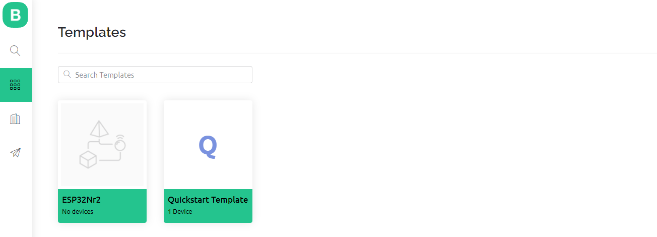
Templates
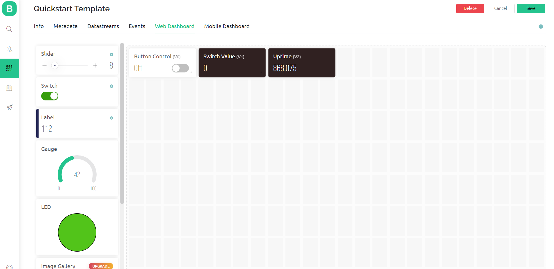
During the quick start, Blynk has not only created a sketch, but also a so-called template. This automatically created version is called “Quickstart Template”. You can access the templates via the menu on the left side of the window. If you select “Edit”, you can change, add or delete widgets. But first, leave things as they are:
The dashboard is created by applying the template to a device. The template determines what the dashboard looks like. Why do you need templates at all? Why aren’t the dashboards edited directly? The answer is: templates are reusable. Imagine using a dozen or more widgets for a device that you have carefully positioned and customized. If you later install another device to do the same thing, you can simply reuse the template. This is object-oriented work: the template is the class, the devices are the objects.
The Quickstart Code
First, the code:
/*************************************************************

  This is a simple demo of sending and receiving some data.
  Be sure to check out other examples!
 *************************************************************/

// Template ID, Device Name and Auth Token are provided by the Blynk.Cloud
// See the Device Info tab, or Template settings
#define BLYNK_TEMPLATE_ID           "Your Template ID"
#define BLYNK_DEVICE_NAME           "Your Device Name"
#define BLYNK_AUTH_TOKEN            "Your Token"


// Comment this out to disable prints and save space
#define BLYNK_PRINT Serial


#include <WiFi.h>
#include <WiFiClient.h>
#include <BlynkSimpleEsp32.h>

char auth[] = BLYNK_AUTH_TOKEN;

// Your WiFi credentials.
// Set password to "" for open networks.
char ssid[] = "Your WiFi Name";
char pass[] = "Your WiFi Password";

BlynkTimer timer;

// This function is called every time the Virtual Pin 0 state changes
BLYNK_WRITE(V0)
{
  // Set incoming value from pin V0 to a variable
  int value = param.asInt();

  // Update state
  Blynk.virtualWrite(V1, value);
}

// This function is called every time the device is connected to the Blynk.Cloud
BLYNK_CONNECTED()
{
  // Change Web Link Button message to "Congratulations!"
  Blynk.setProperty(V3, "offImageUrl", "https://static-image.nyc3.cdn.digitaloceanspaces.com/general/fte/congratulations.png");
  Blynk.setProperty(V3, "onImageUrl",  "https://static-image.nyc3.cdn.digitaloceanspaces.com/general/fte/congratulations_pressed.png");
  Blynk.setProperty(V3, "url", "https://docs.blynk.io/en/getting-started/what-do-i-need-to-blynk/how-quickstart-device-was-made");
}

// This function sends Arduino's uptime every second to Virtual Pin 2.
void myTimerEvent()
{
  // You can send any value at any time.
  // Please don't send more that 10 values per second.
  Blynk.virtualWrite(V2, millis() / 1000);
}

void setup()
{
  // Debug console
  Serial.begin(115200);

  Blynk.begin(auth, ssid, pass);
  // You can also specify server:
  //Blynk.begin(auth, ssid, pass, "blynk.cloud", 80);
  //Blynk.begin(auth, ssid, pass, IPAddress(192,168,1,100), 8080);

  // Setup a function to be called every second
  timer.setInterval(1000L, myTimerEvent);
}

void loop()
{
  Blynk.run();
  timer.run();
  // You can inject your own code or combine it with other sketches.
  // Check other examples on how to communicate with Blynk. Remember
  // to avoid delay() function!
}
The code is explained excellently in the documentation. To get there, click on the round icon in the menu bar on the left, which looks like a lifebuoy. Then go to Documentation → Quickstart → “Quickstart Device: Code Overview”.
I would just like to highlight a few key points:
- In
loop()you will find only two functions:Blynk.run()keeps connected to the Blynk Cloud. The function ensures that inputs in the dashboard are received and processed by the board.timer.run()controls the previously defined timer, which calls the functionmyTimerEvent()every second in this sketch. There you can place all actions that are to be triggered at regular intervals. In this particular case, the system time in seconds is transmitted to Blynk inmyTimerEvent().
BLINK_WRITE(V0)is called every time you change the value of the virtual pin V0 in the dashboard (explanation follows).BLINK_CONNECTED()is called when the device connects to the Blynk Cloud. Here you can make general settings.
The concept of virtual pins
You transfer data via virtual pins to or from your board. Once you understand this concept, the rest is simple. Virtual Pins are the interface for your data to the Blink Cloud. Or you can consider them to be containers in which you transport data to and from the Blink Cloud. The quick start sketch uses the V0, V1, V2, and V3 virtual pins. Which data is assigned to these pins can be found in the corresponding template under “Data streams”.

Let’s take a closer look at Switch Control (V0). Depending on the state of the switch, V0 is either 0 or 1. In the quick start sketch, the function BLYNK_WRITE(V0) reacts to a change from V0. The statement int value = param.asInt(); causes the value of V0 to be interpreted as an integer and assigned to the variable “value”. Blynk.virtualWrite(V1, value); is basically the reverse of this process: The virtual pin V1 (Switch Value) is assigned the value of “value” and reported back to the Blink Cloud. When you press the switch button in the dashboard and the switch value changes, you have confirmation that the process has been executed correctly.
So that something visible finally happens on the microcontroller side, we extend the sketch a little. Define a pin that you call “ledPin”, for example, and set it in setup() to OUTPUT. Then extend BLYNK_WRITE(V0) at the end with digitalWrite(ledPin, value). Now you can turn an LED connected to “ledPin” on and off from anywhere in the world.
The system time in seconds is passed to the virtual pin V2 (Seconds) through Blynk.virtualWrite(V2, millis() / 1000). This happens every second with the occurrence of the timer event in the function myTimerEvent(). The pin V3 is not used in the PC version of the quick start Dashboard, but only on the smartphone.
Creating additional templates and devices with Blynk
Developer mode
If you want to make changes in the Blink console, you must be in developer mode. If nothing works, then the problem could lie there. In this case, go to the user profile (in the menu on the left at the bottom) and flip the switch there. If you do not want to make any further adjustments, you can deactivate the developer mode and thus protect your template from changes.
Additional template
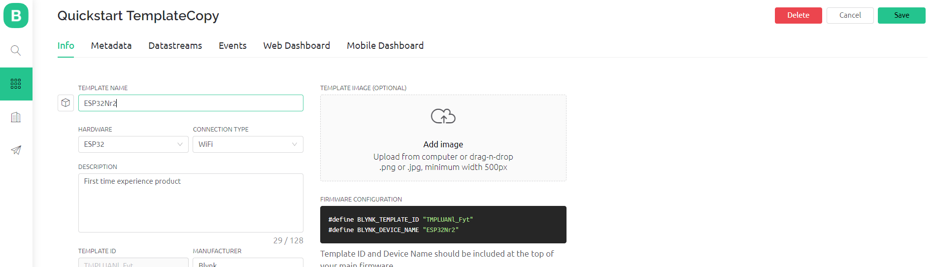
To create another template, it is best to build on an existing one. To do this, navigate to the templates, select the Quick Start template and click on “Clone” in the upper right corner. Then you can make some general adjustments, such as changing the name, hardware, and connection type. A template ID is automatically created, and the name is adopted.
Your new template will then appear in the list. You can see that it has not been applied to any device yet.
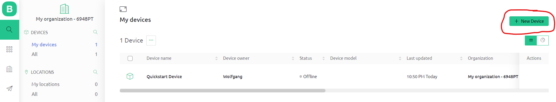
New device
There are several ways to create new devices. I find the following the easiest. Go to the devices (magnifying glass icon) and click on “New Device”.
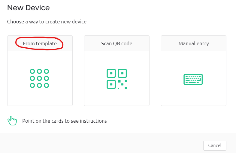
Select “From template”:
Enter the template you want to use and click on “Create”:
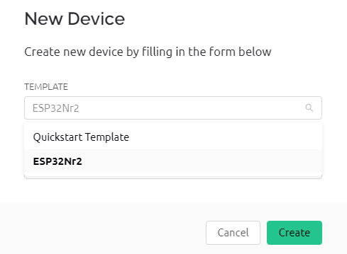
The new device is created. On the right side you can see the template ID, the device name and the authentication token. You can easily copy this data to the clipboard and paste it into your sketch.

There is still the question of where to get the sketch for the new device. There are several options:
- You take an existing Blynk sketch and copy the template ID, device name and token into it. If you change your board (from ESP32 to ESP8266, for example), then you have to make further adjustments. In this case, I would recommend one of the next two options.
- Uses the “Blynk Example Browser”, here is the link.
- You run through the quick start process again, but cancel it after the code creation and copy template ID, device name and token into it.
Once you have created and adapted the sketch, you upload it to your microcontroller board. It should now appear in the device list.
Adding widgets
So far, we have been content with switching the LED and transmitting the system time. That’s still a bit boring. In the next step, we’ll add two more widgets:
- With a slider, the brightness of an LED is to be controlled remotely using PWM.
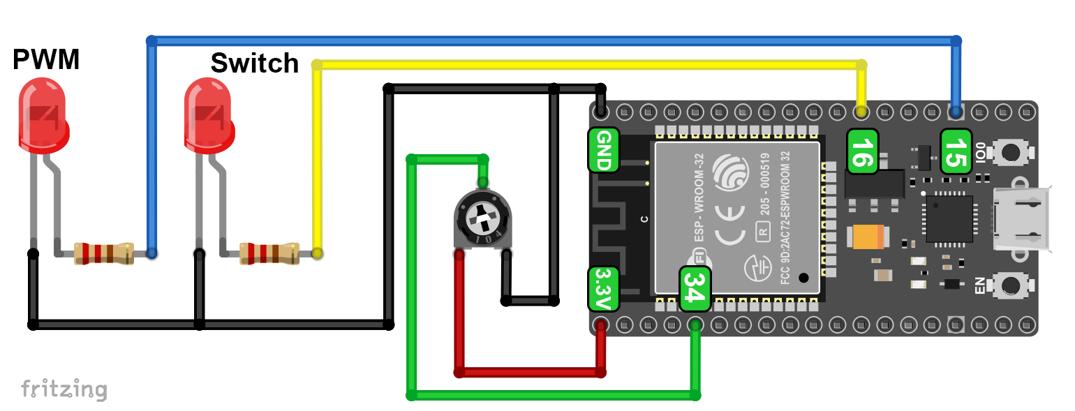
- The measured values of a sensor shall be output on the dashboard and displayed graphically. As a substitute for a sensor value, I take the voltage of a connected potentiometer.
Here is the corresponding simple circuit:
Creating Data Streams / Virtual Pins
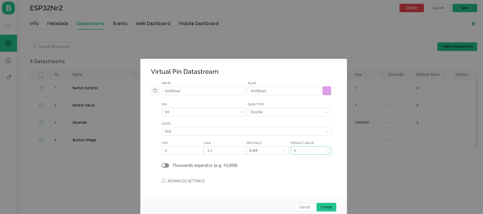
Since we want to transmit additional data, we must first define the corresponding data streams. To do this, go to the templates in the Blynk console, select the template to be changed, go to the tab “Data streams” and then “Edit”. Select New Datastream, and then select Virtual Pin.
I named the data stream for reading the voltage “VoltRead” and assigned it the virtual pin V4. The data type is a floating-point number, and “double” is available for this. For the units, I could have put volts, but I just forgot and was too lazy to repeat everything. The minimum is 0 volts, the maximum 3.3 volts. Then you can choose how many decimal places you want to use. The default value is the start value if there is no measured data yet. When you have entered everything, click on “Create”.
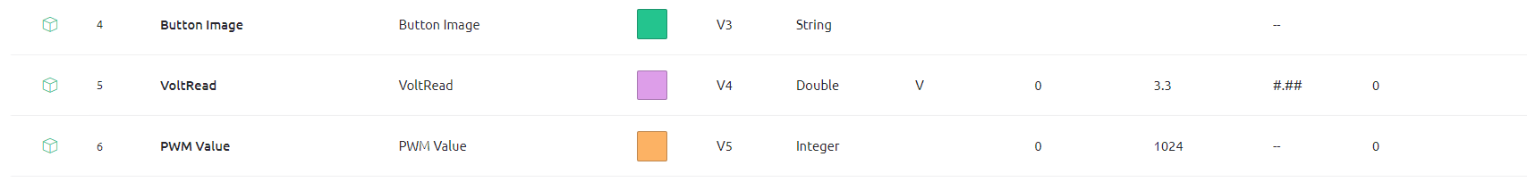
For the PWM control you proceed similarly. I named the data stream “PWM Value”. Since I set the PWM resolution in the sketch to 10 bits, the min/max range is from 0 to 1024. “PWM Value” is an integer:
Selecting and configuring widgets
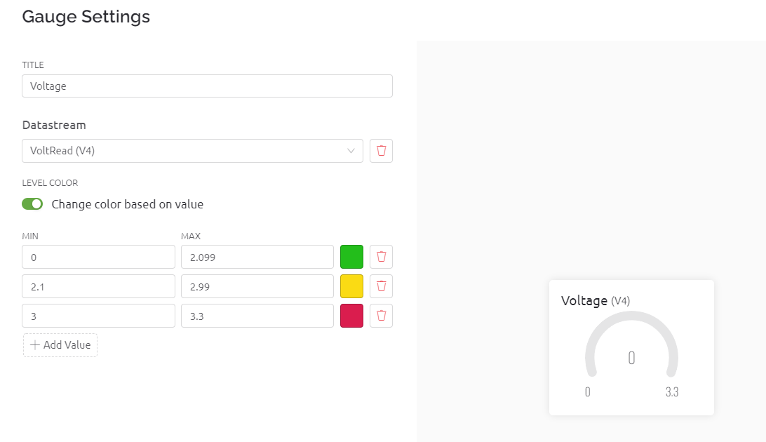
Now we have to assign the data streams to specific widgets. To do this, we switch to the template and edit it. On the left side are the widgets that you can select. For our “VoltRead” we take the widget “Gauge”. Click on the widget and drag it to the desired location. You can also adjust the size. Then click on the gear in the widget and adjust the widget. First of all, you can give the widget a new name. The next point is the most important: you assign the data stream to the widget. As a nice feature, you can change the color of the display depending on the measured value:
For the PWM value, we select a slider and assign virtual pin V5 to it. This is what the template looks like:
Customizing the Sketch
On Blynk console side, we are ready. Now we need to adjust the sketch a bit. We need a PWM pin, PWM settings for the LED and an analogRead pin for the voltage. Then we need to link the virtual pins to real data.
For the PWM control, you will find the function BLYNK_WRITE(V5) in the extended sketch. The transferred value is read as an integer, stored in the variable “dutyCycle” and then applied to the PWM pin.
VoltRead is a value that is regularly read and sent to the Blynk Cloud. To transfer VoltRead we simply extend myTimerEvent() accordingly.
Here is the full sketch:
/*************************************************************

  This is a simple demo of sending and receiving some data.
  Be sure to check out other examples!
 *************************************************************/

// Template ID, Device Name and Auth Token are provided by the Blynk.Cloud
// See the Device Info tab, or Template settings
#define BLYNK_TEMPLATE_ID "Your Template ID"
#define BLYNK_DEVICE_NAME "ESP32Nr2"
#define BLYNK_AUTH_TOKEN "Your Authentification Token"


// Comment this out to disable prints and save space
#define BLYNK_PRINT Serial


#include <WiFi.h>
#include <WiFiClient.h>
#include <BlynkSimpleEsp32.h>

char auth[] = BLYNK_AUTH_TOKEN;

// Your WiFi credentials.
// Set password to "" for open networks.
char ssid[] = "Your WiFi Name (SSID)";
char pass[] = "Your WiFi Password";
const int ledPin = 16;
const int pwmPin = 15;
const int voltagePin = 34;
const int freq = 1000;
const int pwmChannel = 0;
const int res = 10; // 2^10 = 1024

BlynkTimer timer;

// This function is called every time the Virtual Pin 0 state changes
BLYNK_WRITE(V0)
{
  // Set incoming value from pin V0 to a variable
  int value = param.asInt();

  // Update state
  Blynk.virtualWrite(V1, value);
  digitalWrite(ledPin, value); // manually added
}

BLYNK_WRITE(V5)
{
  // Set incoming value from pin V5 to a variable
  int dutyCycle = param.asInt();

  // Update state
  ledcWrite(pwmChannel, dutyCycle);
}

// This function is called every time the device is connected to the Blynk.Cloud
BLYNK_CONNECTED()
{
  // Change Web Link Button message to "Congratulations!"
  Blynk.setProperty(V3, "offImageUrl", "https://static-image.nyc3.cdn.digitaloceanspaces.com/general/fte/congratulations.png");
  Blynk.setProperty(V3, "onImageUrl",  "https://static-image.nyc3.cdn.digitaloceanspaces.com/general/fte/congratulations_pressed.png");
  Blynk.setProperty(V3, "url", "https://docs.blynk.io/en/getting-started/what-do-i-need-to-blynk/how-quickstart-device-was-made");
  Blynk.setProperty(V1, "color", "#D3435C");
}

// This function sends Arduino's uptime every second to Virtual Pin 2.
void myTimerEvent()
{
  // You can send any value at any time.
  // Please don't send more that 10 values per second.
  float voltage = analogRead(voltagePin)*3.3/4095.0;
  Blynk.virtualWrite(V2, millis() / 1000);
  Blynk.virtualWrite(V4, voltage);
  Serial.println(voltage);

}

void setup()
{
  // Debug console
  Serial.begin(115200);
  pinMode(ledPin, OUTPUT);
  ledcSetup(pwmChannel, freq, res);
  ledcAttachPin(pwmPin, pwmChannel);

  Blynk.begin(auth, ssid, pass);
  // You can also specify server:
  //Blynk.begin(auth, ssid, pass, "blynk.cloud", 80);
  //Blynk.begin(auth, ssid, pass, IPAddress(192,168,1,100), 8080);

  // Setup a function to be called every second
  timer.setInterval(1000L, myTimerEvent);
}

void loop()
{
  Blynk.run();
  timer.run();
  // You can inject your own code or combine it with other sketches.
  // Check other examples on how to communicate with Blynk. Remember
  // to avoid delay() function!
}
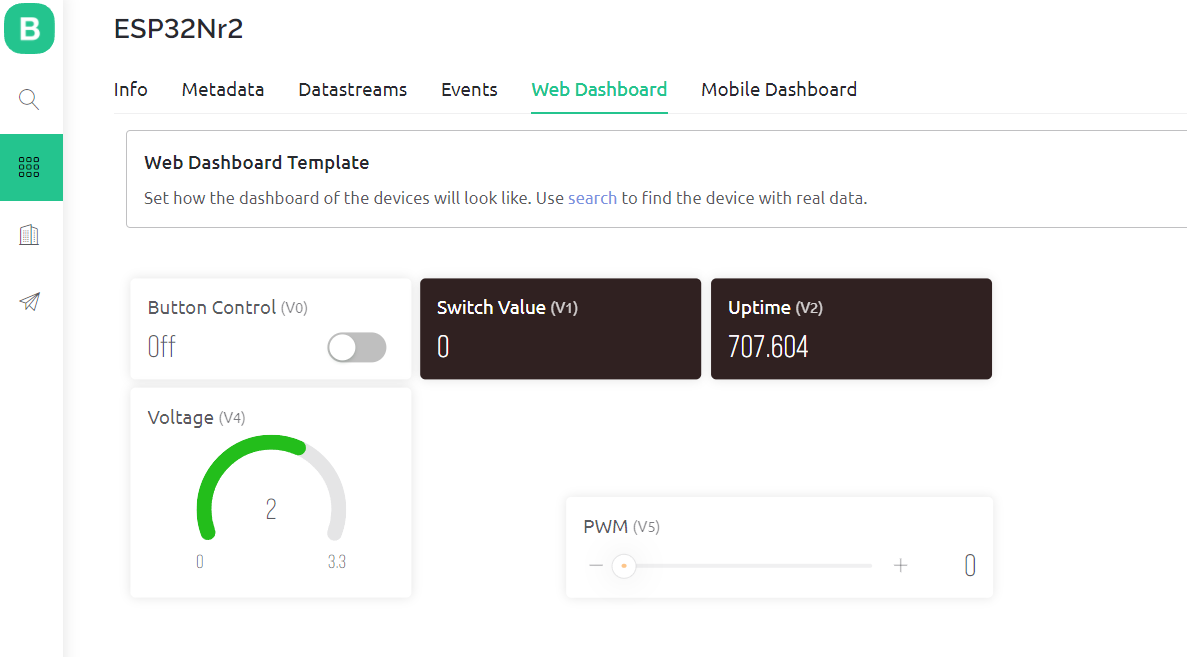
Upload the sketch to your board and go to the dashboard in the Blynk console. Now you can play with the PWM slider or turn the potentiometer and see how the values and color change.

Display measured values over time
You want to display sensor data over time graphically? No problem. Go back to the template and add the widget “Chart” this time. Assign the desired data stream to the chart and apply further settings as desired. This is all self-explanatory. In the free version you can retrieve the data of the last 7 days.

Automations and notifications with Blynk
So far, we have only read data or transmitted data to control things. Now it gets a bit more exciting with automation. Typical examples from home automation would be:
- If the daylight is less than x, close the blinds.
- Turn a lamp on and off at a certain time.
- Notify me when the motion detector is triggered.
Here are two simple examples using my circuit above that you can easily transfer to other applications:
- Turn the LED on and off at specific times.
- If the voltage exceeds 2.2 volts, send me a notification on my smartphone.
First, you need to expose the data streams to automation. To do this, go to your template → Data streams → Edit → Data stream / Virtual pin to be edited. In my example, the affected data streams or virtual pins are V0 and V4. Enable “Advanced Settings” and make your adjustments:

Enable Automation (Switch)
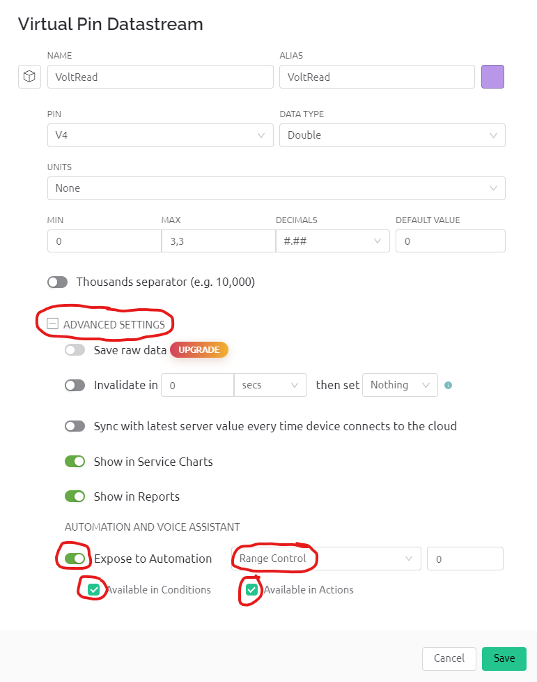
Enable automation (VoltRead)
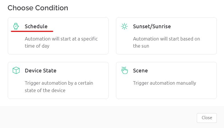
Now go to the Automations section via the menu and select “Add Automation”. To switch on the LED, select the option “Schedule”:
In the next window, you then make settings of your choice:
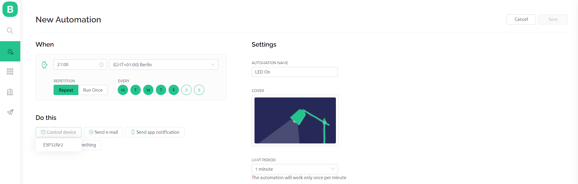
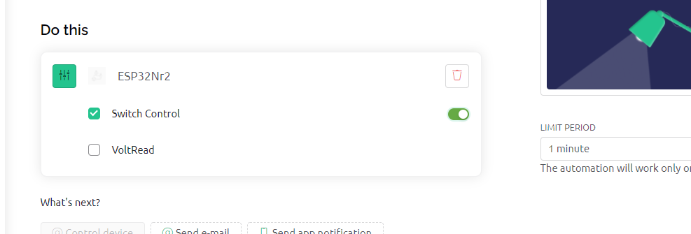
After you have selected the control device (i.e. your microcontroller board), you still have to specify the data stream. To activate, you must set the switch symbol behind Switch Control to “On”:
For the automated switch-off, repeat the whole procedure accordingly.
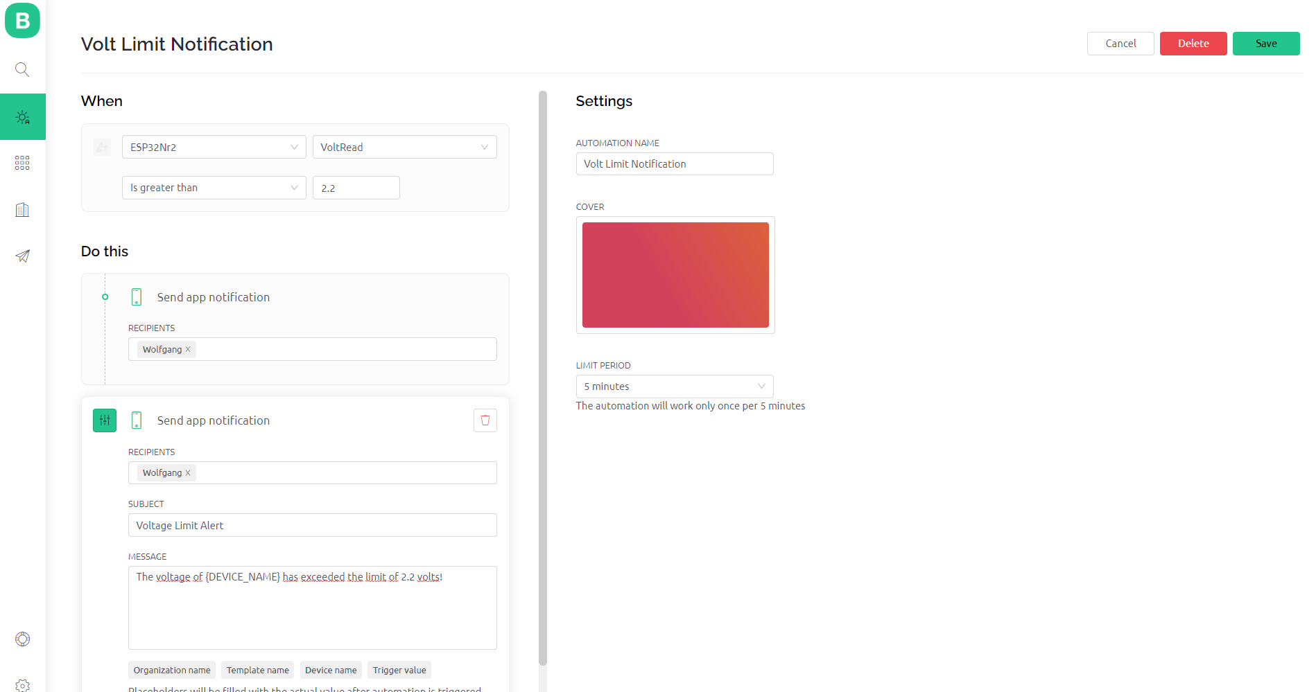
To activate the notification, proceed similarly, but select the option “Device status” in the “Choose condition” window. The other settings are also self-explanatory again. A prerequisite for receiving the message is, of course, that you have stored your phone number in the settings.
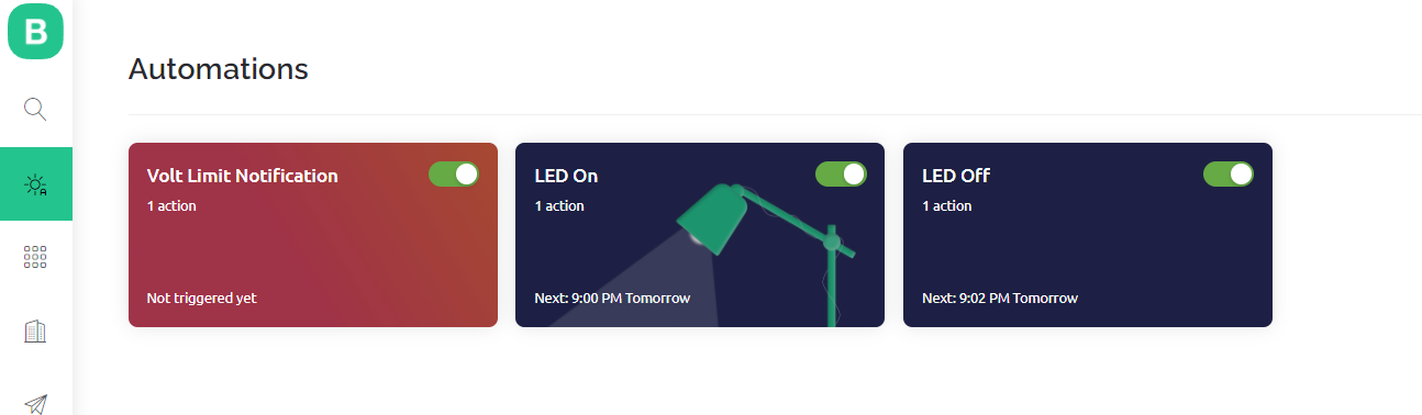
This is what the overview of automations looks like:
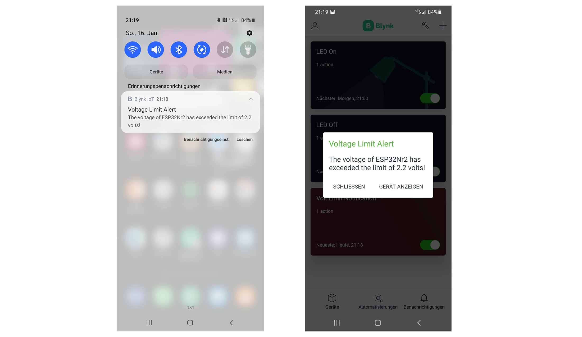
And finally, the notification on the smartphone:
Bypass Blynk’s device limitation
With the two devices that Blynk allows to use in the free version, you may quickly reach your limits. I would like to show you how you can indirectly include other boards without having to pay for a subscription. However, you have to accept the restriction that you can no longer necessarily update your readings every second.
I would like to explain this with a simple example. Voltage values that are determined with another board shall be sent to the board connected to Blynk. From there, the data is sent to Blynk. I use techniques that I explained in my article WLAN with ESP8266 and ESP32. Look there if you don’t understand one or the other.
Setting up the additional board
I’m using another ESP32 board in this example. I might as well have taken an ESP8266 or an Arduino board. The additional board is integrated into the home network as a web server. In the case of a GET request for the main path “/”, the board sends the voltage measured at GPIO34 to the requesting client. This can be programmed with only a few lines:
#include <WebServer.h>

const char* ssid = "Your WiFi Name (SSID)";
const char* pass = "Your WiFi Password";

IPAddress ip(192,168,178,111);
IPAddress gateway(192,168,178,1);
IPAddress subnet(255,255,255,0);

WebServer server(80);

void setup(){
  WiFi.begin(ssid, pass);
  WiFi.config(ip, gateway, subnet);
  server.on("/",handleRoot);
  server.begin();
}

void loop(){
  server.handleClient();
}

void handleRoot(){
  float measuredValue_1 = analogRead(34)/4095.0 * 3.3;
  String message = String(measuredValue_1, 2);
  server.send(200, "text/html", message);
}
Modifying the Blynk Sketch
The query of the additional ESP32 board is initiated in myTimerEvent() by calling the function querySecondESP32(). In this function, a client object is created with which the measured values are queried via a GET request. However, this takes a certain amount of time. And during this time, a new timer event may be triggered. The more additional devices you poll and the higher your timer frequency, the more “collisions” there will be. As a result, more values may be lost. In this example, you will see in the dashboard that the Uptime no longer counts up every second. And if you use the switch, you will see that it sometimes takes two seconds for the LED to react.
For many applications, however, a certain delay will be acceptable. You just have to be aware that the delay effect will increase with every additional devices that you integrate in this way. I would lower the frequency of calling myTimerEvent().
For the additional voltage values, we use the virtual pin (V6).
#define BLYNK_TEMPLATE_ID "Your Template ID"
#define BLYNK_DEVICE_NAME "ESP32Nr2"
#define BLYNK_AUTH_TOKEN "Your Authentification Token"

#define BLYNK_PRINT Serial

#include <WiFi.h>
#include <WiFiClient.h>
#include <BlynkSimpleEsp32.h>

char auth[] = BLYNK_AUTH_TOKEN;

char ssid[] = "Your WiFi Name (SSID)";
char pass[] = "Your WiFi Password";
const char* host_ESP32 = "192.168.178.111"; // IP of the second ESP32
const int ledPin = 16;
const int pwmPin = 15;
const int voltagePin = 34;
const int freq = 1000;
const int pwmChannel = 0;
const int res = 10; // 2^10 = 1024

BlynkTimer timer;

BLYNK_WRITE(V0)
{
  int value = param.asInt();

  Blynk.virtualWrite(V1, value);
  digitalWrite(ledPin, value); // manually added
}

BLYNK_WRITE(V5)
{
  int dutyCycle = param.asInt();

  ledcWrite(pwmChannel, dutyCycle);
}

// This function is called every time the device is connected to the Blynk.Cloud
BLYNK_CONNECTED()
{
  Blynk.setProperty(V3, "offImageUrl", "https://static-image.nyc3.cdn.digitaloceanspaces.com/general/fte/congratulations.png");
  Blynk.setProperty(V3, "onImageUrl",  "https://static-image.nyc3.cdn.digitaloceanspaces.com/general/fte/congratulations_pressed.png");
  Blynk.setProperty(V3, "url", "https://docs.blynk.io/en/getting-started/what-do-i-need-to-blynk/how-quickstart-device-was-made");
  Blynk.setProperty(V1, "color", "#D3435C");
}

// This function sends Arduino's uptime every second to Virtual Pin 2.
void myTimerEvent()
{
  float voltage = analogRead(voltagePin)*3.3/4095.0;
  float voltage2ndESP32 = querySecondESP32();
  Blynk.virtualWrite(V2, millis() / 1000);
  Blynk.virtualWrite(V4, voltage);
  Serial.print("Voltage, this ESP32: "); // just to check things on the Serial Monitor
  Serial.println(voltage);
  Serial.print("Voltage, second ESP32: ");
  Serial.println(voltage2ndESP32); // get voltage from 2nd ESP32
  Blynk.virtualWrite(V6, voltage2ndESP32);
}

void setup()
{
  Serial.begin(115200);
  pinMode(ledPin, OUTPUT);
  ledcSetup(pwmChannel, freq, res);
  ledcAttachPin(pwmPin, pwmChannel);

  Blynk.begin(auth, ssid, pass);
  timer.setInterval(1000L, myTimerEvent);
}

void loop()
{
  Blynk.run();
  timer.run();
}

float querySecondESP32(){
  String voltageString = "none";
  WiFiClient client;
  if (!client.connect(host_ESP32, 80)) {
    Serial.println("connection failed to second ESP32");
    return 0.0;
  }
  String url = "/";
  client.print(String("GET ") + url + " HTTP/1.1\r\n" +
               "Host: " + host_ESP32 + "\r\n" +
               "Connection: close\r\n\r\n");
  unsigned long lasttime = millis();
  while (!client.available() && ((millis() - lasttime) < 3000)){
    delay(1);
  }
  while (client.available()) {
    String line = client.readStringUntil('\r');
    if(line != ""){
      voltageString = line;
    }
  }
  return voltageString.toFloat();
}
Of course, the virtual pin V6 and the data stream still have to be set up in the Blynk console. You also have to create an additional widget in the template. The easiest way is to copy the existing widget and adjust it.
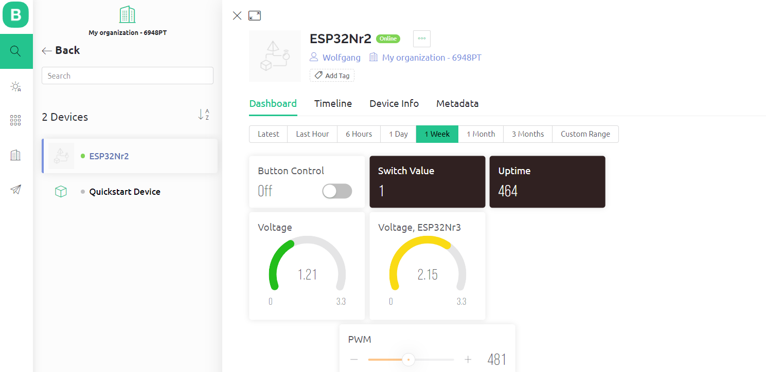
Here is the complete dashboard, including the additional board (ESP32Nr3):