
About this Post
In my last post, I explained the basics of creating libraries and classes. In this second part, I want to show you concretely how to write an Arduino library for a component to be controlled, using the accelerometer and gyroscope MPU6050. Of course, each component has individual properties and the libraries to be developed are correspondingly different. However, you will often encounter certain questions, hurdles, and stumbling blocks regardless of the specific component, and I’ll try to cover them here. Especially if you write your own libraries for sensors, you should be able to transfer a lot from this article.
I have written a detailed separate post about the MPU6050(link). Here, I only address the aspects that are relevant to the topic of this post.
Another important note: I don’t always stick to what I preach in this article with my libraries on GitHub! Many of my erstwhile sins are subject to continuous improvement, but to eliminate all of them I would have to sacrifice backwards compatibility, and that is what I don’t want.
Preparations
You don’t have to buy an MPU6050 to follow this post. But it is certainly more exciting and educational if you can try and vary the code presented here. MPU6050 modules are available for a few euros in online stores.
I have written the library MPU6050_JFL for this article. Here, “JFL” stands for “just for learning” because I don’t want to give the impression that this is a complete library (although of course it works!).
You can download MPU6050_JFL, including the example sketches, directly from GitHub here. I described how to install libraries “manually” in the last post. You will not find MPU6050_JFL via the Arduino library management. It would not make sense to add such a training object to the Arduino library collection.

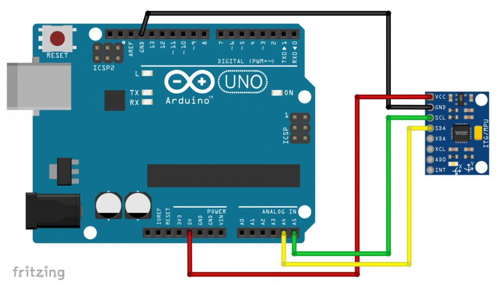
The connection to the Arduino or other microcontrollers is simple. GND to GND, VCC to 5 volts (most modules have a voltage regulator), SDA to SDA and SCL to SCL. Whether you still need pull-up resistors or level shifters depends on the module. With ADO, you can set the I2C address. If ADO is unconnected or pulled down to GND level, the address is 0x68. If you pull ADO up to HIGH level, the address is 0x69. At least this applies to the modules I use.
Studying the data sheet
Before you start the development of a library for an electronic component, you will have to read the data sheet. The data sheets are usually not written according to didactic principles and are therefore often difficult to digest. Over time, however, you get practice reading them. It’s been my experience that when reading for the first time, don’t linger long on sections you don’t understand. Things often clarify themselves as you go along or when you do a second reading.
For the MPU6050, there is a product specification of 52 pages and a register overview of another 46 pages. The good news is that you don’t need to read those documents to understand this post! You should take a look anyway.
The registers of the MPU6050
What are registers?
Registers are special memory areas where you can write data to, or read data from. Registers have a name and an internal address. Components controlled with registers can be thought of as a control panel from the last century. In some registers, functions or settings of the components are activated or deactivated. These are the switches. In other registers, parameters can be regulated. This makes them the knobs or sliders, so to speak. Still, other registers contain measured values or other information and thus represent displays. In essence, libraries are about mastering this control panel and “translating” cryptic register instructions into understandable functions.
Considered registers
The MPU6050 has more than one hundred registers. We consider only a small part of it:
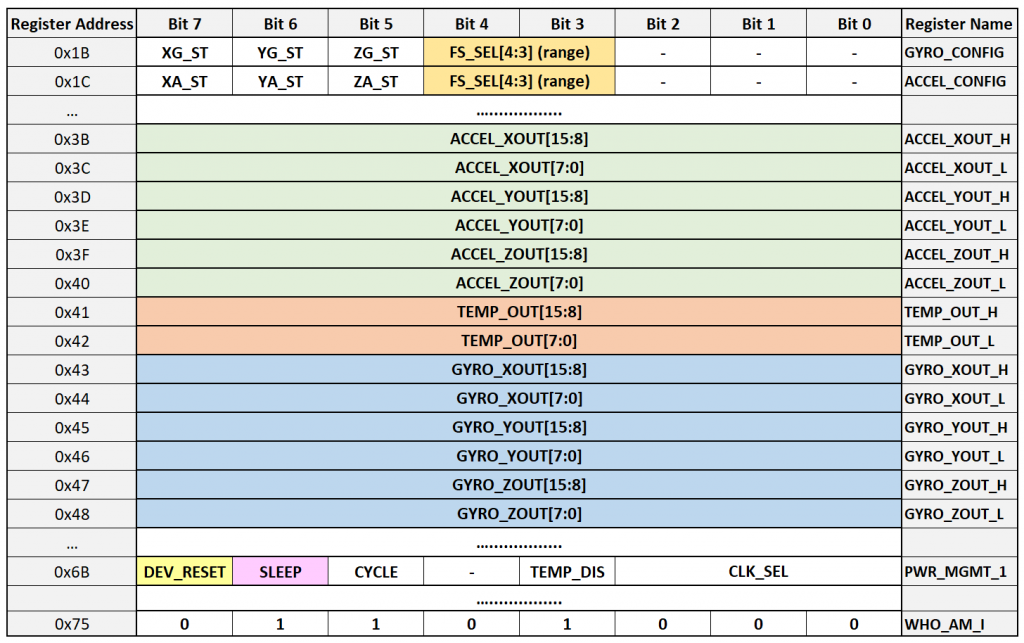
The GYRO_CONFIG and ACCEL_CONFIG registers contain the FS_SEL (Full Scale Select) bits, which are used to set the measuring ranges for the accelerometer and the gyroscope.
The acceleration and rotation measurement values are determined separately for the x, y and z axes. They comprise 16 bits each and are therefore divided into two registers each, e.g. ACCEL_XOUT_H and ACCEL_XOUT_L for the acceleration of the x-axis. Since the measured values can be positive or negative, the range of each axis is from -215 to +215 (strictly speaking: -215 to 215-1).
The raw values can be retrieved from the measured value registers. They must be converted into acceleration values in g or rotation values in dps (degrees per second), considering the current measuring range. In other words, if you have set a measuring range of +/- 2 g, the raw value 32767 (=215-1) means an acceleration of + 2 g. If your measuring range is +/- 4 g, the same raw value means an acceleration of + 4 g.
![\[ \text{accelerationValue [g]} = \frac{\text{rawValue}\cdot \text{range\,\text[g]}}{32767} \]](https://wolles-elektronikkiste.de/wp-content/ql-cache/quicklatex.com-45e0c6b6506a20e6f28e16aa28183184_l3.png "Rendered by QuickLaTeX.com")
The MPU6050 also has a temperature sensor. It outputs the raw value as a 16-bit number. The formula for the conversion to temperature in degrees Celsius is (see data sheet):
![\[ T\;[°\text{C}] = \frac{\text{rawValue}}{340}+36.53 \]](https://wolles-elektronikkiste.de/wp-content/ql-cache/quicklatex.com-6e9ef75b97c601688b520ad5e4a595da_l3.png "Rendered by QuickLaTeX.com")
The POWER_MGMT_1 (Power Management 1) register contains two bits that we consider in our library. If you set the DEV_RESET bit (Device Reset), the MPU6050 is reset. This resets all registers to the default settings. DEV_RESET is then automatically deleted. If the SLEEP bit is set, the MPU6050 is in sleep mode. You wake it up by deleting the bit.
Finally, we consider the WHO_AM_I register. It is read-only and contains the value 0x68. This will help you to ensure that the IC on your module is really an MPU6050.
First step: the “torso” and communication
There’s more than one way to skin a cat! And so, of course, there are different strategies for how you create libraries or classes. In school, you first learn to take a sheet of paper, list the methods and functions, draw schematics with boxes, etc. Personally, I’m too impatient for that and try to get to a first result as quickly as possible to stimulate the reward center in my brain!
For example, a nice first success would be to simply read the WHO_AM_I register. Since the MPU6050 is an I2C device, you need a reading function for Wire. If you’re not familiar with Wire functions, look here.
A minimal header file could look like this:
#include "Arduino.h"
#include "Wire.h"

#ifndef MPU6050_JFL_H_
#define MPU6050_JFL_H_

constexpr uint8_t MPU6050_WHO_AM_I{0x75};
// alternative:
// #define MPU6050_WHO_AM_I 0x75

class MPU6050_JFL
{
    public:
        MPU6050_JFL(const uint8_t addr)
        : i2cAddress{addr} {}

        uint8_t whoAmI();

    private:
        uint8_t i2cAddress;
        uint8_t readRegister(uint8_t reg);
};

#endif
This would be the corresponding source file:
#include <MPU6050_JFL.h>

uint8_t MPU6050_JFL::whoAmI(){
    return readRegister(MPU6050_WHO_AM_I);
}

uint8_t MPU6050_JFL::readRegister(uint8_t reg){
    uint8_t data;
    Wire.beginTransmission(i2cAddress);
    Wire.write(reg);
    Wire.endTransmission(false);
    Wire.requestFrom(i2cAddress, (uint8_t)1);
    data = Wire.read();
    return data;
}
And with this sketch, you would then be able to read the WHO_AM_I register:
#include <MPU6050_JFL.h>
#include <Wire.h>
#define I2C_ADDRESS 0x68

MPU6050_JFL myMPU = MPU6050_JFL(I2C_ADDRESS);

void setup() {
  Wire.begin();
  Serial.begin(9600);
  Serial.print("Who Am I: 0x");
  Serial.println(myMPU.whoAmI(),HEX);
}

void loop(){}
For an SPI device or one that communicates via UART, I would proceed similarly. For I2C devices you can use the read function readRegister() in numerous instances. But there are also exceptions. Therefore, take a look at the data sheet of the component you want to control.
Two more notes about the minimal library:
- I usually pass the I2C address to the constructor and use it in the class as a global variable. Global variables should be used as little as possible. Alternatively, you can pass the I2C-address with each function call. This is a question of convenience and comfort vs. effectiveness.
- Many library authors use
#define xxx yyyfor definitions (I used to do the same!). However, a safer and clearer solution isconstexpr datatype xxx{yyy}.
If you have prior knowledge of libraries and classes, then the minimal library should be easy to understand. If you have any difficulties, perhaps take another look at my last post.
And how to proceed? In the next step, I added a write function for registers (writeRegister()) and tested it. And from this starting point, you can gradually add more functions. But instead of going through each evolutionary step, let’s make a leap to the result.
The complete MPU6050_JFL – An Overview
The MPU6050_JFL library consists of a header file (“.h”) and a source file (“.cpp”), both with the same name. It contains only one class, which also has the same name. I show the library files in full here. The discussion follows in the next chapters.
This is the header file:
#include "Arduino.h"
#include "Wire.h"

#ifndef MPU6050_JFL_H_
#define MPU6050_JFL_H_

enum accel_range{
    MPU6050_ACCEL_RANGE_2G = 0,
    MPU6050_ACCEL_RANGE_4G,
    MPU6050_ACCEL_RANGE_8G,
    MPU6050_ACCEL_RANGE_16G
};

enum class GyroRange : uint8_t{
    MPU6050_250DPS  = 0x00,
    MPU6050_500DPS  = 0x08,
    MPU6050_1000DPS = 0x10,
    MPU6050_2000DPS = 0x18
};

struct xyzFloat {
    float x;
    float y;
    float z;
};

class MPU6050_JFL
{
    public:
        static constexpr uint8_t MPU6050_GYRO_CONFIG       {0x1B};
        static constexpr uint8_t MPU6050_ACCEL_CONFIG      {0x1C};
        static constexpr uint8_t MPU6050_ACCEL_XOUT_H      {0x3B};
        static constexpr uint8_t MPU6050_ACCEL_XOUT_L      {0x3C};
        static constexpr uint8_t MPU6050_ACCEL_YOUT_H      {0x3D};
        static constexpr uint8_t MPU6050_ACCEL_YOUT_L      {0x3E};
        static constexpr uint8_t MPU6050_ACCEL_ZOUT_H      {0x3F};
        static constexpr uint8_t MPU6050_ACCEL_ZOUT_L      {0x40};
        static constexpr uint8_t MPU6050_TEMP_OUT_H        {0x41};
        static constexpr uint8_t MPU6050_TEMP_OUT_L        {0x42};
        static constexpr uint8_t MPU6050_GYRO_XOUT_H       {0x43};
        static constexpr uint8_t MPU6050_GYRO_XOUT_L       {0x44};
        static constexpr uint8_t MPU6050_GYRO_YOUT_H       {0x45};
        static constexpr uint8_t MPU6050_GYRO_YOUT_L       {0x46};
        static constexpr uint8_t MPU6050_GYRO_ZOUT_H       {0x47};
        static constexpr uint8_t MPU6050_GYRO_ZOUT_L       {0x48};
        static constexpr uint8_t MPU6050_PWR_MGMT_1        {0x6B}; // Device defaults to the SLEEP mode
        static constexpr uint8_t MPU6050_WHO_AM_I          {0x75}; // Should return 0x68
        static constexpr uint8_t MPU6050_ACCEL_RANGE_MASK  {0x18}; // = 0b00011000
        static constexpr uint8_t MPU6050_GYRO_RANGE_MASK   {0x18}; // = 0b00011000
        static constexpr uint8_t MPU6050_DEVICE_RESET      {0x80};
        static constexpr uint8_t MPU6050_DEVICE_SLEEP      {0x40};

        MPU6050_JFL(const uint8_t addr = 0x68)
        : i2cAddress{addr} {/* empty */}

        bool init();
        bool reset();
        void sleep(bool sl);
        uint8_t whoAmI();
        void setAccelRange(accel_range range);
        uint8_t getAccelRange();
        void setGyroRange(GyroRange range);
        float getOnlyTemperature();
        xyzFloat getAccelerationData();
        void getGyroscopeData(xyzFloat *gyro);
        void update();
        void getGyroscopeDataFromAllRawData(xyzFloat *gyro);

    protected:
        uint8_t i2cAddress;
        float accelRangeFactor;
        float gyroRangeFactor;
        xyzFloat accel;
    uint8_t allRawData[14];
        uint8_t writeRegister(uint8_t reg, uint8_t regValue);
        uint8_t readRegister(uint8_t reg);
        uint16_t read2Registers(uint8_t reg);
        void readMultipleRegisters(uint8_t reg, uint8_t count, uint8_t *buf);
};

#endif
And here is the source file:
#include <MPU6050_JFL.h>

bool MPU6050_JFL::init(){
    //Wire.setWireTimeout();
    accelRangeFactor = 1.0;
    gyroRangeFactor = 1.0;
    bool connected = !reset();
    delay(100); // MPU6050 needs 100 ms to reset
    sleep(false); // disable sleep
    delay(100); // give the device some time to wake up!
    return connected;
}

bool MPU6050_JFL::reset(){
    return writeRegister(MPU6050_PWR_MGMT_1, MPU6050_DEVICE_RESET);
}

void MPU6050_JFL::sleep(bool sl){
    uint8_t regVal = readRegister(MPU6050_PWR_MGMT_1);
    if(sl){
        regVal |= MPU6050_DEVICE_SLEEP;
    }
    else{
        regVal &= ~MPU6050_DEVICE_SLEEP;
    }
    writeRegister(MPU6050_PWR_MGMT_1, regVal);
}

uint8_t MPU6050_JFL::whoAmI() {
    return readRegister(MPU6050_WHO_AM_I);
}

void MPU6050_JFL::setAccelRange(accel_range range){
    uint8_t regVal = readRegister(MPU6050_ACCEL_CONFIG);
    switch(range){
        case MPU6050_ACCEL_RANGE_2G:  accelRangeFactor = 2.0;  break;
        case MPU6050_ACCEL_RANGE_4G:  accelRangeFactor = 4.0;  break;
        case MPU6050_ACCEL_RANGE_8G:  accelRangeFactor = 8.0;  break;
        case MPU6050_ACCEL_RANGE_16G: accelRangeFactor = 16.0;  break;
    }
    regVal &= ~MPU6050_ACCEL_RANGE_MASK;
    regVal |= range<<3;
    writeRegister(MPU6050_ACCEL_CONFIG, regVal);
}

void MPU6050_JFL::setGyroRange(GyroRange range){
    uint8_t regVal = readRegister(MPU6050_ACCEL_CONFIG);
    switch(range){
        case GyroRange::MPU6050_250DPS:  gyroRangeFactor = 250.0;  break;
        case GyroRange::MPU6050_500DPS:  gyroRangeFactor = 500.0;  break;
        case GyroRange::MPU6050_1000DPS: gyroRangeFactor = 1000.0;  break;
        case GyroRange::MPU6050_2000DPS: gyroRangeFactor = 2000.0;  break;
    }
    regVal &= ~MPU6050_GYRO_RANGE_MASK;
    regVal |= static_cast<uint8_t>(range);
    writeRegister(MPU6050_GYRO_CONFIG, regVal);
}

uint8_t MPU6050_JFL::getAccelRange(){
    uint8_t regVal = readRegister(MPU6050_ACCEL_CONFIG);
    regVal = (regVal >> 3) & 0x03;
    return regVal;
}

float MPU6050_JFL::getOnlyTemperature(){
    uint16_t rawTemp = read2Registers(MPU6050_TEMP_OUT_H);
    float temp = (static_cast<int16_t>(rawTemp))/340.0 + 36.53; // see RegMap page 30;
    return temp;
}

xyzFloat MPU6050_JFL::getAccelerationData(){
    uint8_t rawData[6];
    readMultipleRegisters(MPU6050_ACCEL_XOUT_H, 6, rawData);
    accel.x = (static_cast<int16_t>((rawData[0] << 8) | rawData[1]))/32768.0 * accelRangeFactor;
    accel.y = (static_cast<int16_t>((rawData[2] << 8) | rawData[3]))/32768.0 * accelRangeFactor;
    accel.z = (static_cast<int16_t>((rawData[4] << 8) | rawData[5]))/32768.0 * accelRangeFactor;
    return accel;
}

void MPU6050_JFL::getGyroscopeData(xyzFloat *gyro){
    uint8_t rawData[6];
    readMultipleRegisters(MPU6050_GYRO_XOUT_H, 6, rawData);
    gyro->x = (static_cast<int16_t>((rawData[0] << 8) | rawData[1]))/32768.0 * gyroRangeFactor;
    gyro->y = (static_cast<int16_t>((rawData[2] << 8) | rawData[3]))/32768.0 * gyroRangeFactor;
    gyro->z = (static_cast<int16_t>((rawData[4] << 8) | rawData[5]))/32768.0 * gyroRangeFactor;
}

void MPU6050_JFL::update(){
    readMultipleRegisters(MPU6050_ACCEL_XOUT_H, 14, allRawData);
}

void MPU6050_JFL::getGyroscopeDataFromAllRawData(xyzFloat *gyro){
    readMultipleRegisters(MPU6050_GYRO_XOUT_H, 6, allRawData);
    gyro->x = ((static_cast<int16_t>(allRawData[8] << 8) | allRawData[9]))/32768.0 * gyroRangeFactor;
    gyro->y = ((static_cast<int16_t>(allRawData[10] << 8) | allRawData[11]))/32768.0 * gyroRangeFactor;
    gyro->z = ((static_cast<int16_t>(allRawData[12] << 8) | allRawData[13]))/32768.0 * gyroRangeFactor;
}

uint8_t MPU6050_JFL::writeRegister(uint8_t reg, uint8_t regValue){
    Wire.beginTransmission(i2cAddress);
    Wire.write(reg);
    Wire.write(regValue);

    return Wire.endTransmission();
}

uint8_t MPU6050_JFL::readRegister(uint8_t reg){
    uint8_t data;
    Wire.beginTransmission(i2cAddress);
    Wire.write(reg);
    Wire.endTransmission(false);
    Wire.requestFrom(i2cAddress, static_cast<uint8_t>(1));
    data = Wire.read();
    return data;
}

uint16_t MPU6050_JFL::read2Registers(uint8_t reg){
    uint8_t MSB = 0, LSB = 0; // (Most / Least Significant Byte)
    uint16_t regValue = 0;
    Wire.beginTransmission(i2cAddress);
    Wire.write(reg);
    Wire.endTransmission(false);
    Wire.requestFrom(i2cAddress, static_cast<uint8_t>(2));
    MSB = Wire.read();
    LSB = Wire.read();

    regValue = (MSB<<8) + LSB;
    return regValue;
}

void MPU6050_JFL::readMultipleRegisters(uint8_t reg, uint8_t count, uint8_t *buf){
    Wire.beginTransmission(i2cAddress);
    Wire.write(reg);
    Wire.endTransmission(false);
    uint8_t i = 0;
    Wire.requestFrom(i2cAddress, count);
    while (Wire.available()) {
        buf[i] = Wire.read();
        i++;
    }
}
Definition of registers and register values
For the designation of the registers and some register values, I use constexpr – expressions. Since the definition is placed within the class, the keyword static must be added, for example: static constexpr uint8_t MPU6050_GYRO_CONFIG {0x1B};.
The definition within the class reduces the risk of name collisions. Outside the class, the identifiers are not known. If you still want to use them outside the class, you must prefix them with the class name, separated by the scope resolution operator ::, e.g. MPU6050_JFL::MPU6050_GYRO_CONFIG.
Another way to avoid name collisions would be to use a nameless namespace. To do this, you place the constexpr definitions in the source file (without static) and there within a namespace environment: namespace{....}. However, then you cannot use the identifiers outside the source file. This could cause problems with inheritances – but I just realize I’m getting lost in details….
However, these measures do not protect you from others possibly using the same names in #define – or constexpr – expressions without such precautions in libraries you want to include. So, you should still use individual names and not something like “CONFIG_REGISTER” for example.
Constructor
There is not much to say about the constructor. It receives the I2C address as parameter. If no address is passed during object initialization, then the default 0x68 will be applied.
Initialization
We will look at the init() function in detail:
bool MPU6050_JFL::init(){
    //Wire.setWireTimeout();
    accelRangeFactor = 1.0;
    gyroRangeFactor = 1.0;
    bool connected = !reset();
    delay(100); // MPU6050 needs 100 ms to reset
    sleep(false); // disable sleep
    delay(100); // give the device some time to wake up!
    return connected;
}
In many libraries, a init() or begin() function provides a defined initial state. In addition, the function is often used to determine whether the component is functional. This is also the case here. If the MPU6050 module is responsive, connected is returned as true.
Wire.setWireTimeout() ensures that the sketch does not hang in case of a faulty I2C communication. If you leave the function commented out, it can happen (but doesn’t have to) that init() fails to complete on error, so you won’t get any feedback.
I will come back to the variables accelRangeFactor and gyrRangeFactor later.
The reset() function
The reset() function writes 0x80 (= 0b10000000) to the register MPU6050_PWR_MGMT_1. So, it sets the DEV_RESET bit.
bool MPU6050_JFL::reset(){
    return writeRegister(MPU6050_PWR_MGMT_1, MPU6050_DEVICE_RESET);
}
The function writeRegister() returns the return value of Wire.endTransmission() (line 113). If successful, this is a 0 (false). In case of an error, an error code is returned, i.e. a value different from 0 (true). The return value is passed back to init() and inverted there by bool connected = !reset(). It would be illogical if init() returned false in case of success.
If the component you want to control has a reset function, you should use it as part of the initialization for your libraries. If it should do not exist, then I advise setting the registers “manually” to initial values. Otherwise, the following can happen: You play with your code and upload a new version to your microcontroller. It will be reset during the upload, but your component will not be reset unless it has been disconnected from the power supply. Thus, the registers still have their values from the last program run. This undefined state can lead to unpredictable errors.
After the reset, the MPU6050 needs up to 100 milliseconds to be ready for use again. This value is in the data sheet.
The sleep() function
A reset sets all registers of the MPU6050 to zero, except for the registers PWR_MGMT_1 and, of course, WHO_AM_I. The default value of PWR_MGMT_1 is 0x40, i.e. the sleep bit is set. In other words: after a reset, the MPU6050 is asleep and must first be woken up. To do this, we need to clear the sleep bit using a suitable function. However, the function should also make it possible to set the sleep bit again later to send the MPU6050 to sleep at any time. Moreover, the function shall not influence the other bits of the register PWR_MGMT_1.
These requirements are met by sleep():
void MPU6050_JFL::sleep(bool sl){
    uint8_t regVal = readRegister(MPU6050_PWR_MGMT_1);
    if(sl){
        regVal |= MPU6050_DEVICE_SLEEP;
    }
    else{
        regVal &= ~MPU6050_DEVICE_SLEEP;
    }
    writeRegister(MPU6050_PWR_MGMT_1, regVal);
}
In sleep(), first the content of the register PWR_MGMT_1 is read. After that, if sleep() was called with the parameter true, the following part of the if clause is executed:
regVal |= MPU6050_DEVICE_SLEEP;
// entspricht / equals:
// regVal = regVal | 0b01000000;
And in case of false:
regVal &= ~MPU6050_DEVICE_SLEEP;
// entspricht / equals:
// regVal = regVal & 0b10111111;
In both cases, only the sleep bit of the register value is effected. The modified register value is then written back. If you want to know more about such binary operations, it’s best to read my post on the subject.
Alternatively, you can set up two separate functions for sleeping and waking and thus dispense with parameter passing – it’s your choice.
Setting the measuring range
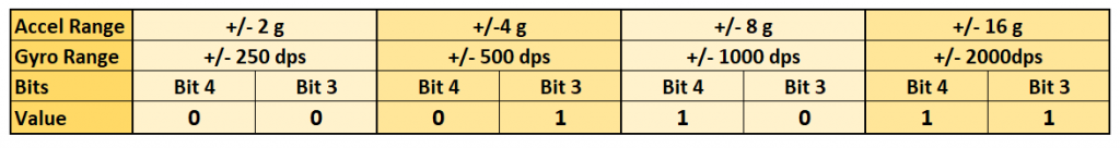
For the acceleration and the gyroscope values there are 4 measuring ranges each, which are set by the FS_SEL bits (3 and 4) in the corresponding configuration registers according to the following scheme:
For naming the measuring ranges of the accelerometer, I use enum definitions, which I declared in the header file:
enum accel_range{
    MPU6050_ACCEL_RANGE_2G = 0,
    MPU6050_ACCEL_RANGE_4G,
    MPU6050_ACCEL_RANGE_8G,
    MPU6050_ACCEL_RANGE_16G
};
The measuring ranges are passed to the corresponding functions, e.g. setAccelRange(MPU6050_ACCEL_RANGE_2G). Of course, it would also be possible to simply pass 2, 4, 8 or 16. Such an approach is pragmatic, but makes your libraries error-prone in operation. For example, you could pass a “42” without the compiler reporting an error. With a bulky expression like MPU6050_ACCEL_RANGE_2G, on the other hand, there is a risk of producing typos, but syntax highlighting can be used to minimize the risk. Moreover, the compiler complains if you want to pass an undefined expression.
It is recommended to use enum classes instead of the simple enum definitions. They are more “data type safe” because unintentional type conversions are prevented. They also reduce the risk of name collisions. To show the difference between both options, I defined the gyroscope measurement ranges as an enum class:
enum class GyroRange : uint8_t{
    MPU6050_250DPS  = 0x00,
    MPU6050_500DPS  = 0x08,
    MPU6050_1000DPS = 0x10,
    MPU6050_2000DPS = 0x18
};
To access the elements of the enum class, you must prefix them with the class name, separated by the scope resolution operator ::, for example: GyroRange::MPU6050_250DPS.
Measuring range of the accelerometer
Let’s look at the setAccelRange() function in detail:
void MPU6050_JFL::setAccelRange(accel_range range){
    uint8_t regVal = readRegister(MPU6050_ACCEL_CONFIG);
    switch(range){
        case MPU6050_ACCEL_RANGE_2G:  accelRangeFactor = 2.0;  break;
        case MPU6050_ACCEL_RANGE_4G:  accelRangeFactor = 4.0;  break;
        case MPU6050_ACCEL_RANGE_8G:  accelRangeFactor = 8.0;  break;
        case MPU6050_ACCEL_RANGE_16G: accelRangeFactor = 16.0;  break;
    }
    regVal &= ~MPU6050_ACCEL_RANGE_MASK;
    regVal |= range<<3;
    writeRegister(MPU6050_ACCEL_CONFIG, regVal);
}
I had defined the accelRange values to correspond to FS_SEL bits 3 and 4. I.e.the value for 2 g is 0, for 4 g it is 1, for 8 g it is 2, and for 16 g it is 3. Unlike the manipulation of the sleep bit, we are dealing with two bits in this case. Therefore, we need to change the approach a bit. We again read the content of the relevant register (here: ACCEL_CONFIG), but then we first clear the FS_SEL bits:
regVal &= ~MPU6050_ACCEL_RANGE_MASK;
//entspricht / equals:
//regVal = regVal & 0b11100111;
Then we set the passed bits using the logical OR (i.e. |), but we still have to shift them by 3 bits to the left:
regVal |= range<<3;
In setAccelRange() we also set accelRangeFactor. We need this value when calculating the acceleration values from the raw data. I took the liberty of defining the variable globally. Alternatively, you could query the measuring range with getAccelRange() before each query of measured values and thus dispense with this global variable. However, this comes at the expense of speed.
To query the measuring range using getAccelRange(), we read the ACCEL_CONFIG register, shift the value three places to the right and eliminate everything that may still be to the left of the FS_SEL bits:
regVal = (regVal >> 3) & 0x03;
Measuring range of the gyroscope
For the definition of the gyroscope measuring ranges, I applied another change, besides using an enum class. The elements of gyro_range do not correspond to the FS_SEL bits but they also reflect the position in the GYRO_CONFIG register. In other words, they are already shifted three bits to the left, so you have to do this later. Which variant you prefer is a matter of taste.
I have dispensed with a getGyroRange() function. If you want to practice a little, you could add it.
Reading raw data and calculation of the measured values
If a sensor outputs several measured data, then there are different approaches how you query them, read the raw data and return the measured values determined from them.
Reading raw data values individually
The raw data of the measured values of the MPU6050 are divided into two registers each. The most obvious solution is therefore to implement a function that reads the two registers, composes the raw value from them and returns it to the requesting function. And that’s precisely what the read2Registers() function does:
uint16_t MPU6050_JFL::read2Registers(uint8_t reg){
    uint8_t MSB = 0, LSB = 0; // (Most / Least Significant Byte)
    uint16_t regValue = 0;
    Wire.beginTransmission(i2cAddress);
    Wire.write(reg);
    Wire.endTransmission(false);
    Wire.requestFrom(i2cAddress, static_cast<uint8_t>(2));
    MSB = Wire.read();
    LSB = Wire.read();

    regValue = (MSB<<8) + LSB;
    return regValue;
}
Here you can see how to use read2Registers() using the function getOnlyTemperature() as an example:
float MPU6050_JFL::getOnlyTemperature(){
    uint16_t rawTemp = read2Registers(MPU6050_TEMP_OUT_H);
    float temp = (static_cast<int16_t>(rawTemp))/340.0 + 36.53; // see RegMap page 30;
    return temp;
}
Note that the raw value is read as an uint16_t number and then converted to an int16_t number.
Reading multiple raw values in one go (Burst Read)
You could do the same with the x, y and z values for acceleration and rotation, namely individually. However, this is not very effective because you have to “renegotiate” each read operation with the MPU6050. Reading several values at once is faster.
To make the reading function flexible, we pass it the number of registers to be read. And to save memory, we use pointers:
void MPU6050_JFL::readMultipleRegisters(uint8_t reg, uint8_t count, uint8_t *buf){
    Wire.beginTransmission(i2cAddress);
    Wire.write(reg);
    Wire.endTransmission(false);
    uint8_t i = 0;
    Wire.requestFrom(i2cAddress, count);
    while (Wire.available()) {
        buf[i] = Wire.read();
        i++;
    }
}
The function has no return value because we are working with the original that was passed as uint8_t *buf.
The next question is how to return the values to the calling sketch. One option, of course, would be to use an array. In my accelerometer and gyroscope libraries, I decided to define a structure called xyzFloat, which consists of the three float values x, y and z:
struct xyzFloat {
    float x;
    float y;
    float z;
};
This is how the function for querying the acceleration values looks like:
xyzFloat MPU6050_JFL::getAccelerationData(){
    uint8_t rawData[6];
    readMultipleRegisters(MPU6050_ACCEL_XOUT_H, 6, rawData);
    accel.x = (static_cast<int16_t>((rawData[0] << 8) | rawData[1]))/32768.0 * accelRangeFactor;
    accel.y = (static_cast<int16_t>((rawData[2] << 8) | rawData[3]))/32768.0 * accelRangeFactor;
    accel.z = (static_cast<int16_t>((rawData[4] << 8) | rawData[5]))/32768.0 * accelRangeFactor;
    return accel;
}
The three acceleration values, i.e. six individual values, are queried and stored in the array rawData. The function calculates the three acceleration values from raw value pairs and saves them as accel which is a xyzFloat. I have defined the variable accel in MPU6050_JHL.h.
Ich halte es für besser, den Wertetripel als Zeiger als Zeiger zu übergeben. To show how this can be done, I have implemented this procedure for the gyroscope values.
void MPU6050_JFL::getGyroscopeData(xyzFloat *gyro){
    uint8_t rawData[6];
    readMultipleRegisters(MPU6050_GYRO_XOUT_H, 6, rawData);
    gyro->x = (static_cast<int16_t>((rawData[0] << 8) | rawData[1]))/32768.0 * gyroRangeFactor;
    gyro->y = (static_cast<int16_t>((rawData[2] << 8) | rawData[3]))/32768.0 * gyroRangeFactor;
    gyro->z = (static_cast<int16_t>((rawData[4] << 8) | rawData[5]))/32768.0 * gyroRangeFactor;
}
This way we can get rid of the local variable gyro and the function has no return value.
The passed variable *gyro is a pointer. The pointer itself is not xyzFloat, but merely refers to it. The pointer also has no element x, y or z. Therefore, instead of the point operator, the arrow operator must be used, i.e. gyro->x. Alternatively, (*gyro).x is also possible, but this is unusual.
Another option would be to pass gyro by reference, i.e. getGyroscopeData(xyzFloat &gyro){...}. Then you could avoid the arrow operators. Personally, I think the pointer method is better because it is clearer that the original is being used and not a local copy. But that is a matter of taste.
Example sketch
After all the explanations, it’s time to take a look at the MPU6050 library in action using an example sketch:
#include <MPU6050_JFL.h>
#include <Wire.h>
#define I2C_ADDRESS 0x68

MPU6050_JFL myMPU = MPU6050_JFL(I2C_ADDRESS);
// alternative:
//MPU6050_JFL myMPU = MPU6050_JFL();

void setup() {
  Wire.begin();
  Serial.begin(9600);
  if(myMPU.init()){
    Serial.println("MPU6050 connected");
  }
  else{
    Serial.println("MPU6050 not connected");
    while(1);
  }
  Serial.print("Who Am I: 0x");
  Serial.println(myMPU.whoAmI(),HEX);
  myMPU.setAccelRange(MPU6050_ACCEL_RANGE_2G);
  myMPU.setGyroRange(GyroRange::MPU6050_500DPS);
  Serial.print("Acceleration Range (0-3): ");
  Serial.println(myMPU.getAccelRange());
  Serial.print("Temperature [°C]: ");
  Serial.println(myMPU.getOnlyTemperature());
  Serial.println();
}

void loop(){
  xyzFloat acc = myMPU.getAccelerationData();
  xyzFloat gyr = {0.0, 0.0, 0.0};
  myMPU.getGyroscopeData(&gyr);
  Serial.print("acc_x: ");
  Serial.print(acc.x); Serial.print('\t');
  Serial.print("acc_y: ");
  Serial.print(acc.y); Serial.print('\t');
  Serial.print("acc_z: ");
  Serial.println(acc.z);

  Serial.print("gyr_x: ");
  Serial.print(gyr.x); Serial.print('\t');
  Serial.print("gyr_y: ");
  Serial.print(gyr.y); Serial.print('\t');
  Serial.print("gyr_z: ");
  Serial.println(gyr.z);
  Serial. println();

  delay(2000);
}
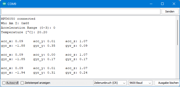
You can see here the differences when calling getAccelerationData() and getGyroscopeDateData(). Otherwise, the sketch should not need any explanations. Here is the output:
Reading all raw data at once
So far, we have read the acceleration, gyroscope and temperature values separately. If you need all these values and high speed is important, you can, of course, read all raw data at once. For this purpose, I introduced a global variable uint8_t allRawData[14] which is updated by the update() function:
void MPU6050_JFL::update(){
    readMultipleRegisters(MPU6050_ACCEL_XOUT_H, 14, allRawData);
}
The functions for calculating the measured values are then reading the raw data from allRawData. I have implemented this as an example only for the gyroscope values:
void MPU6050_JFL::getGyroscopeDataFromAllRawData(xyzFloat *gyro){
    readMultipleRegisters(MPU6050_GYRO_XOUT_H, 6, allRawData);
    gyro->x = ((static_cast<int16_t>(allRawData[8] << 8) | allRawData[9]))/32768.0 * gyroRangeFactor;
    gyro->y = ((static_cast<int16_t>(allRawData[10] << 8) | allRawData[11]))/32768.0 * gyroRangeFactor;
    gyro->z = ((static_cast<int16_t>(allRawData[12] << 8) | allRawData[13]))/32768.0 * gyroRangeFactor;
    return gyro;
}
In the associated sketch example_2.ino, an update must be initiated via update() before each query of the measured values.
#include <MPU6050_JFL.h>
#define I2C_ADDRESS 0x68

MPU6050_JFL myMPU = MPU6050_JFL(I2C_ADDRESS);

void setup() {
  Serial.begin(9600);
  if(myMPU.init()){
    Serial.println("MPU6050 connected");
  }
  else{
    Serial.println("MPU6050 not connected");
    while(1);
  }
  myMPU.setGyroRange(GyroRange::MPU6050_500DPS);
}

void loop(){
  myMPU.update();
  xyzFloat gyr;
  myMPU.getGyroscopeDataFromAllRawData(&gyr);

  Serial.print("gyr_x: ");
  Serial.print(gyr.x); Serial.print('\t');
  Serial.print("gyr_y: ");
  Serial.print(gyr.y); Serial.print('\t');
  Serial.print("gyr_z: ");
  Serial.println(gyr.z);

  delay(2000);
}
Another option to “package” the measured values would be a single large struct object:
struct MPU6050_result {
    float acc_x;
    float acc_y;
    float acc_z;
    float temp;
    float gyr_x;
    float gyr.y;
    float gyr.z;
};
Other MPU6050 libraries
There are even more ways to read and process the measured values. If you feel like it, check out other libraries for MPU6050 on GitHub, for example MPU6050 by Kris Winer. The example sketch MPU6050BasicExample.ino shows that the library only returns the raw values, and the actual calculation is “outsourced” to the sketch. This makes the library very slim and does not use global variables, but it makes it a little less convenient to use (my personal opinion!).
If you want to know how to calculate angles from acceleration values, I recommend having a look at the Arduino-MPU6050 library written by Korneliusz Jarzębski.
An example of an MPU6050 library that allows Wire objects to be passed is MPU6050_tockn. This has the advantage that you can make use of the two I2C interfaces of the ESP32 (see also here). In my libraries for I2C and SPI based devices, I generally allow passing of Wire and SPI objects.
Conclusion
I hope this post was helpful and not too much confusing, and motivates you to write your own libraries. You should have noticed that it is not possible to create exact instructions for this, since there are very different approaches even for one and the same component. Try it out and look in other libraries – that’s the fastest way to learn from my point of view.
You might also want to expand the MPU6050_JFL library further? Then, of course, you should first take a step back and choose the one you like best from the many different options I have introduced.
THANK YOU !
Your are welcome! I appreciate that “Thank you”!
Hi Wofgang.Hope you are well.I like your projects,can you perhaps advise on the following.I have a gun sounds app on my phone.What I want to do is use the headphones input to be triggered by a relay from a laser led circuit.So you hit the Ldr with the laser ,this triggers the relay NO contact,these two wires is connected to the headphone jack.The gun app is open on the phone,when the headphone gets the signal it must trigger a specific gun sound,chosen beforehand,and then the sound will,go via bluetooth to a speaker.I just want to know how I can get the headphone input to trigger the feature on the app.Can ou perhaps give some advice please.Many thanks.Regards
Hi Marinus, as far as I know there is no way to use the headphone jack of your smartphone as an input. To my best knowledge it’s output only. And even if this was possible, I don’t know how to tell an app that an event on the headphone jack shall trigger something. Sorry, I think I can’t help.